
Abstract
To address the industrial need for manufacturing advanced thermoplastic composite parts with less energy, waste, and time and at lower cost, the feasibility of automated fiber placement using ultrasonic consolidation (UC) is investigated as an alternative to hot gas torch, laser, and infrared (IR) heating. The flexural stiffness and strength of simple flat parts made using UC and also thermal pressing per manufacturer’s specifications are measured by three-point bending and compared. Whereas UC proved to be more effective in welding polyethylene terephthalate/carbon prepreg tape than thermal pressing for both unidirectional and quasi-isotropic layups, the opposite was true for high-density polyethylene/glass, although optimal welding process parameters may not have been used. Finally, a simple transient conduction model is used to predict temperature rise in the thickening laminate and is compared to experimental measurements.
Introduction
Additive manufacturing (AM) processes, not limited in definition to just three-dimensional printing, are becoming more popular in industry, especially aerospace 1 because they allow for more efficient, increasingly cost-effective manufacturing of composite structures. Two of the most common AM processes for laying up thermoset and thermoplastic composite laminates using reinforcement pre-impregnated with polymer matrix (prepreg) are automated fiber placement (AFP) and automated tape layup (ATL). With AFP, a number of separate small-width tows (usually ≤8 mm) are automatically laid onto a mold or mandrel for manufacturing complex geometries or very small structures. 2,3 ATL, which uses a wider prepreg unidirectional tape for each layer, is generally used for simpler geometries but can cover large areas relatively quickly.
While thermoset prepreg tape is still the most common composite system used for AFP, 4 thermoplastic composite materials are typically more chemically resistant, tougher (less brittle), and more fatigue resistant than thermosets. On the process side, thermoplastic composites reduce or eliminate the need for any post-processing steps, for example, curing by autoclaving, 5 as previously mentioned. These advantages make thermoplastic composite structures very desirable in high-performance products areas, such as aerospace and military.
Currently, thermoplastic composite prepreg layers are preheated for bonding and consolidating (typically with a roller) to previously deposited layers in AFP using three main methods, namely, (1) gas torch heating, (2) laser heating, and (3) infrared (IR) heating. These heating methods, although effective and used commercially, are not particularly energy efficient, are often slow, and can require expensive equipment. 5 Another heating method that has seen surprisingly little consideration is ultrasonic consolidation (UC). In this process, an ultrasonic horn contacts the top prepreg ply, applies a desired pressure, and vibrates at high frequency (10s of thousands of hertz) to locally heat the material, primarily at interfaces. This focused heating combined with applied pressure significantly reduces the amount of energy used, increases the welding speed, and may be able to eliminate the need for post processing (i.e. autoclave consolidation).
This article describes an experimental investigation of rapid heating and direct pressure consolidation of thermoplastic composite prepreg for AFP using an ultrasonic horn oriented at a right angle to the tool surface and compares this to thermal consolidation, specifically using a heated press. A schematic of how UC might be implemented in hardware is shown in Figure 1. To provide context, prior work (papers and patents) related to prepreg heating for AFP is discussed in the next section. The subsequent two sections describe the design and fabrication of hardware to perform thermoplastic prepreg welding experiments, an experimental design using this equipment, a simple model to predict time-varying temperature, present data/results and, finally, concluding remarks/future work.
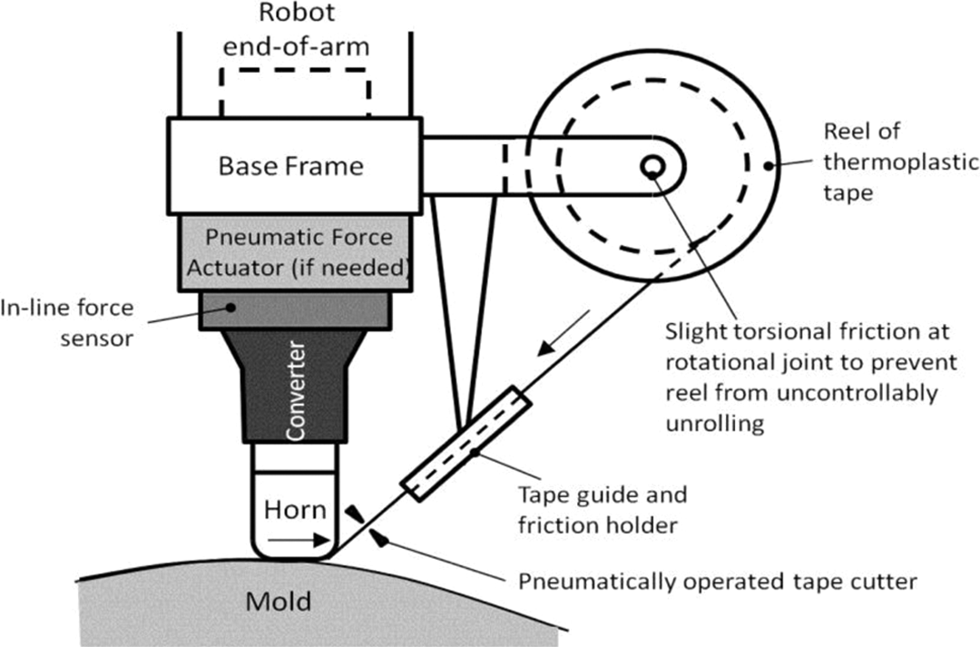
UC/bonding concept for thermoplastic prepreg AFP.
Prior art for thermoplastic AFP
The advantages of AFP systems are well documented. These systems allow large composite structures to be built in flat or mildly contoured layups, provide 70–85% reductions in man-hours (as opposed to machine-hours), and reduce material waste from 25–30% in manual layup systems to about 5% using AFP and ATL. 6 One of the major factors leading to the increase in the popularity of AFP systems over other layup and consolidation methods is cost reduction. Composite materials are very expensive relative to competing metals, costing as much as 10–20 times more by weight 3 , so any additional decrease in cost and cycle time would further increase the effectiveness of AFP from an industry perspective. The following sections describe prior work with different thermoplastic prepreg heating methods including using hot gas, IR, laser, and ultrasonic in pursuit of reduced cost, time, and energy consumption.
Hot gas heating
Hot gas heating is arguably the most common method used in industry for ATL of thermoplastic prepreg material. It is also the most popular choice for welding or repair of thermoplastic parts, 7 so it is easy to see why the process would be used for thermoplastic prepreg. Using a torch to weld thermoplastic material is not a new idea; for example, Phillips 8 patented a torch system for welding thermoplastic tape in 1945. This process is similar to open flame welding of metals, with the major difference being that a stream of hot gas is used instead of direct flame. 9 More recently, Hauber 10 patented a hot gas torch (HGT) design where a stream of heated nitrogen is directed at the desired weld area to raise the temperature of prepreg tape above its glass transition. A roller applying a consolidation force then compresses the tape into the previous ply. A diagram of this patented system is shown in Figure 2.
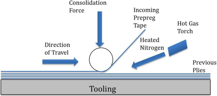
Schematic of an AFP process with HGT. 10
Although hot gas heating is very effective at achieving high temperatures, especially for high-performance thermoplastics such as polyether ether ketone (PEEK), too much of the available energy is wasted by trying to heat convectively. Additionally, in some high-performance applications, such as aerospace, customers still require autoclave consolidation of their thermoplastic composite laminates made by AFP using an HGT to further reduce void content (<2% target), which further adds to the overall process energy consumption. The hot gas method is also relatively slow and complicated to control, making it a poor candidate for products requiring high production rates. 9 Despite the shortcoming of the hot gas method, the weld can maintain as much as 90% of the bulk strength of the material when properly done. 7
IR heating
IR heating is very similar to open flame heating, with the major difference being that the IR source is brought close to the two parts being welded, but never touching the surface. Heat transfer to the composite workpiece is done essentially through radiation. IR heating is commonly used for preheating unconsolidated thermoplastic prepreg layups prior to thermoforming or forming a double diaphragm over a rigid mold. 11 Yousefpour et al. 9 has shown that IR welding is capable of rapidly and consistently producing 40% of the strength of compression molded composite parts. Nejahad et al. 12 –18 did significant work in the area of IR in situ thermoplastic composite consolidation as well. The work has shown that residual stresses can be reduced in parts while still maintaining high dimensional stability. This process has also been thermally analyzed extensively to develop an understanding of the effects that different processing parameters have on the resulting composite properties. While the IR process would not be ideal for all parts, it could be very effective in certain applications.
In addition to the reproducibility and the speed potential of IR welding, the process is noncontact, which greatly reduces the risk of contamination and allows for more consistent welds that retain a higher percentage of the bulk strength. 19 With consistent, proven materials, including those with very low or very high melting points, IR welding can lead to very reproducible results. 20 However, different pigments and additives in the polymer, including some fibers, can affect the IR absorption properties of the material and potentially produce inconsistent or reduced quality welds. 19 A more significant issue is that IR heating is inherently an inefficient method of transferring heat and also uniformly heating thermoplastic composite tape prior to AFP.
Laser heating
Laser-assisted AFP of thermoplastic matrix composites has been investigated for almost three decades. Beyeler et al. 21 first demonstrated the basic concept, which was called the ‘laser-assisted consolidation process’, in the mid-1980s. Having overcome many of the issues that previously prevented it from being an effective prepreg heating method for AFP including matrix overheating and high capital equipment cost, laser heating is now a commercially available process. 22,23 First, lasers have become more robust while significantly dropping in cost. Second, previous work involved pulsed lasers, which resulted in energy spikes that would burn the surface of the tape rather than gradually heat it; continuous wave power output has essentially eliminated this problem. Third, newer lasers no longer directly affect the composite matrix, but instead operate at different light wavelengths to heat the fiber, which is less likely to cause damage to the composite. 24
Ultrasonic heating
The most recent research on ultrasonic heating/consolidation of prepreg composite tape for AFP focuses on the use of ultrasonics in conjunction with a thermal post-processing step. Foster-Miller patented several concepts for using ultrasonics in composites processing including a means to lower resin viscosity for thermoset prepreg, 25 expanding the process to include thermoplastics and a separate pressure shoe, 26 and design of an ultrasonic horn oriented at a small acute angle to the tool surface. 27 The company demonstrated this process, called ultrasonic tape lamination, for debulking and B-staging thermoset prepreg composites. 28 More recent work with ultrasonic welding of thermoplastic composites has shown that the use of energy directors (EDs), that is, protrusions on one of the welding surfaces, results in better welding with less fiber disruption. 29 However, formation of EDs in composite prepreg for use in UC would require an additional processing step. Similar to the method used herein, Lee et al. 30 patented a method for debulking thermoset and thermoplastic composite laminates solely using an ultrasonic horn oriented and vibrating perpendicular to the laminate surface and pushed with high force into the surface. However, there is no mention of applying this approach to either AFP or ATL. A recent patent by Inston 31 for Airbus S.A.S. describes a thermoplastic composite ATL/AFP system that uses a heating source (preferably a laser) combined with a vibrating ultrasonic horn to weld and consolidate thermoplastic composites as part of an ATL/AFP system (see Figure 3). Labeled parts in this figure include (10) upper layer of thermoplastic material being laid down, (12) existing lower layer of thermoplastic material, (14) ultrasonic transducer applying energy to the desired point, (16) desired welding point, and (18) localized heating source.
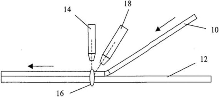
Schematic of a patented process for thermal/UC. 31
The research described herein advances the current state of UC of thermoplastic composites by (1) demonstrating full consolidation without additional localized heating using a specially designed horn oriented at a right angle to the mold surface; (2) focusing on the simplest welding case first, that is, unidirectional tape in parallel plies; and (3) then showing the feasibility of making layups of simple geometry in multiple layers with different ply orientation. The research aims to show that direct ultrasonic welding during AFP, that is, not combined with other heating methods as described previously, has the capacity to manufacture composites parts with comparable performance to the standard of thermal welding, while decreasing the time to process and the energy used. However, it does not compare process consumption or resulting part performance directly with the other heating methods (hot gas, IR, laser), which is reserved for future work.
Hardware
All UC experiments were performed using a 20-kHz Branson 2000× ultrasonic welder with a custom-designed titanium horn (see Figure 4(a)) with 242 mm2 of contact area for continuous composite welding and custom-built lower stage (commonly called an anvil) that supports the workpieces being welded. Since the horn itself supplies a gain of approximately 3× and a 1.5× booster was used, the converter amplitude of about 20 µm is amplified to a total amplitude (peak-to-peak) of 20 µm × 1.5 × 3 = 90 µm. 32
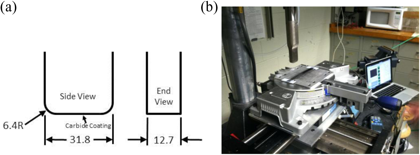
(a) Side and end views of ultrasonic horn geometry (all dimensions are in millimetres) and (b) UC experimental setup. UC: ultrasonic consolidation.
The stage, shown in Figure 4(b), was designed to allow for automated motion control along the welding direction (X), manual motional control in the in-plane transverse direction (Y), and control over the angle of the layup with respect to the weld direction (±45° range). These three degrees of freedom were afforded through the use of two perpendicular stages (one manual and one powered) and a manual rotational stage fixed to the top. The powered stage oriented parallel to the weld direction was controlled using a Kollmorgen p7000 controller and supplied software to provide precise control over the travel distance, travel speed, and acceleration/deceleration of the stage. This made it possible to test the effect of welding traverse speed (WTS) on laminate strength. The manual stage was oriented perpendicular to the powered stage, allowing for small manual steps in between each weld equal to the prepreg tape width. The rotary stage, fixed to the top of the setup, made it possible to easily set up cross ply layups at set angles (e.g. ±45°, ±30°, and ±15°). The entire stage was mounted to the ultrasonic welder’s leveling base, which allowed the stage to be leveled with respect to the horn.
The thermal samples were produced using a Carver Model 4386 (Wabash, Indiana, USA) heated hydraulic press. This press is equipped with two West 6100+ temperature controllers, used to precisely heat the platens. The press also utilizes a force gauge, which allows for constant force monitoring.
Experimental procedure
Two main layups were used for the experimental tests, namely, unidirectional and quasi-isotropic. Two different composite material systems were tested for each layup:
Unidirectional layups
For unidirectional layups, all laminate workpieces were made slightly larger than the specified specimen size and then machined down to a consistent size for flexural testing (three-point bending). For the HDPE/glass tape, at least five replicate specimens were fabricated to test each bonding method, that is, thermal pressing or ultrasonic welding. Each specimen was produced by consolidating 16 individual unidirectional plies of the prepreg tape. As specified by the manufacturer, the thermally pressed samples were bonded at 480 kPa and 180°C for 4 min and then cooled at pressure. The ultrasonic samples essentially had two process variables: weld traverse speed (WTS) and frequency amplitude (FA) as shown in Table 1. The WTS-2/FA-1 process parameters (same set of conditions) were determined from preliminary qualitative experiments that showed that at 0.5 s of weld time, both HDPE/glass and PET/carbon experienced suitable welds, but without significant spreading. These values were used as base levels from which all other process parameters were varied, with the other process parameters changing certain values from the WTS-2 parameters. Welding pressure was held constant at 220 kPa. The effective weld time value shown in Table 1 refers to the amount of time the ultrasonic horn spends welding each individual point in the laminate. The weld time refers to the total amount of time the ultrasonic welder is actively welding a laminate layer. The welding traverse speed refers to the speed of the stage moving underneath the horn, indicating the speed with which the sample moves relative to the horn. The frequency amplitude refers to the amplitude as a percentage of the total amplitude of 90 µm for this machine (20 kHz).
Ultrasonic welding process variables.
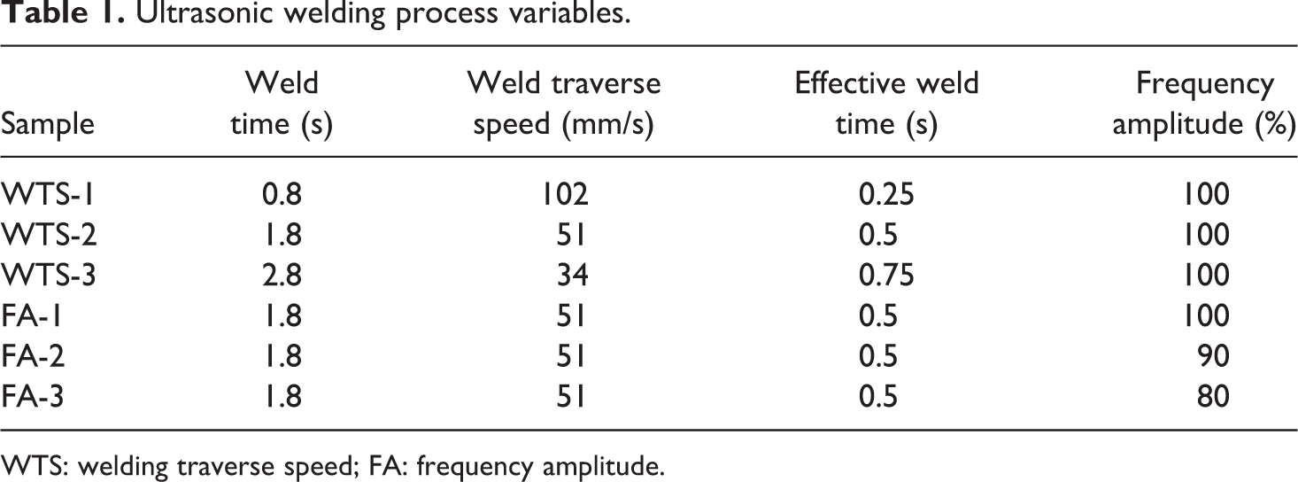
WTS: welding traverse speed; FA: frequency amplitude.
The thermal PET/carbon samples were bonded at 480 kPa and 271°C for 4 min and then cooled at pressure, as specified by the manufacturer. 34 Ultrasonic bonding process variables and conditions used for the PET/carbon specimens were the same as HDPE/glass. Each specimen was produced by consolidating 16 unidirectional plies.
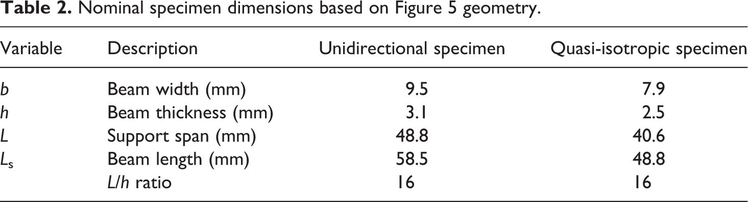
The ultrasonically consolidated specimens were tested using an Instron 5848 Microtester (Norwood, Massachusetts, USA) and a variable three-point bend test apparatus per ASTM standard D7264 (see Figure 5(a)). The geometry and dimensions of the specimens tested, shown in Figure 5(b) and Table 2, respectively, extended over the supports by at least their thickness. It should be noted that the dimensions in Table 2 are average values, and actual dimensions of each sample were measured with Vernier calipers and used in all strength and stiffness calculations. The crosshead speed was set to 1 mm/min per the ASTM standard with failure indicated by one of the following conditions, namely, (1) load drop off by 30%, (2) two-piece specimen failure, or (3) head travel exceeds specimen thickness.
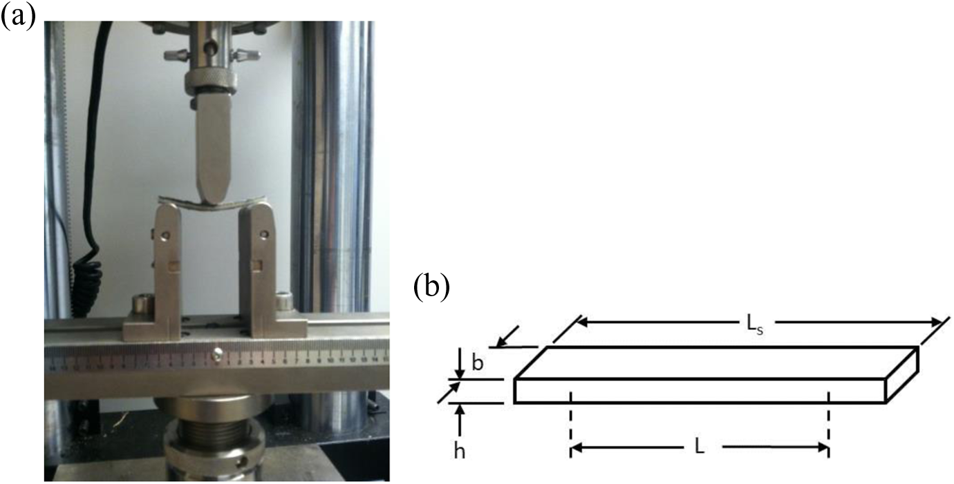
(a) PET/carbon beam specimen in 3-point bending test apparatus and (b) composite laminate specimen geometry used. PET: polyethylene terephthalate.
Nominal specimen dimensions based on Figure 5 geometry.
Flexural secant modulus and flexural strength were calculated for each beam specimen per ASTM D7264. The flexural secant modulus is found using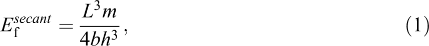
where L = support span, m = slope of the secant of the force-deflection curve, b = width of beam and h = thickness of the beam. The flexural stress at the lower outer surface at mid span is found using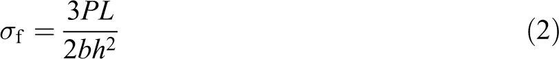
where P is the applied force measured using the Instron microtester.
Quasi-isotropic layups
These eight-ply laminates, consisting of a [−45/0/45/90]s layup, were made under similar conditions, both thermally and ultrasonically, but in much larger panels. The panels were then machined into smaller beam samples, also per ASTM D7264 standard. The ultrasonic quasi-isotropic panel was produced using optimal process parameters for unidirectional layups (WTS-3 shown in Table 1), further discussed in results section. The specimens were created by consolidating eight plies using the orientations shown in Figure 6(a), with each ply made up of five segments of tape lined up side by side and welded 16 times using a 7.6-mm offset between each weld. Since each weld is 95 mm in length, this leads to a total welded area of 11,550 mm2. In the end, a panel of 121.6 × 95 mm2 was created. By doing this, a much smaller ultrasonic horn was used to weld a much larger panel by comparison. A picture of panel welding is shown in Figure 6(b). Note that the images in Figure 6(a) are only a schematic to clearly show the ply layup sequence; in reality, there is significantly less material overhang than shown.
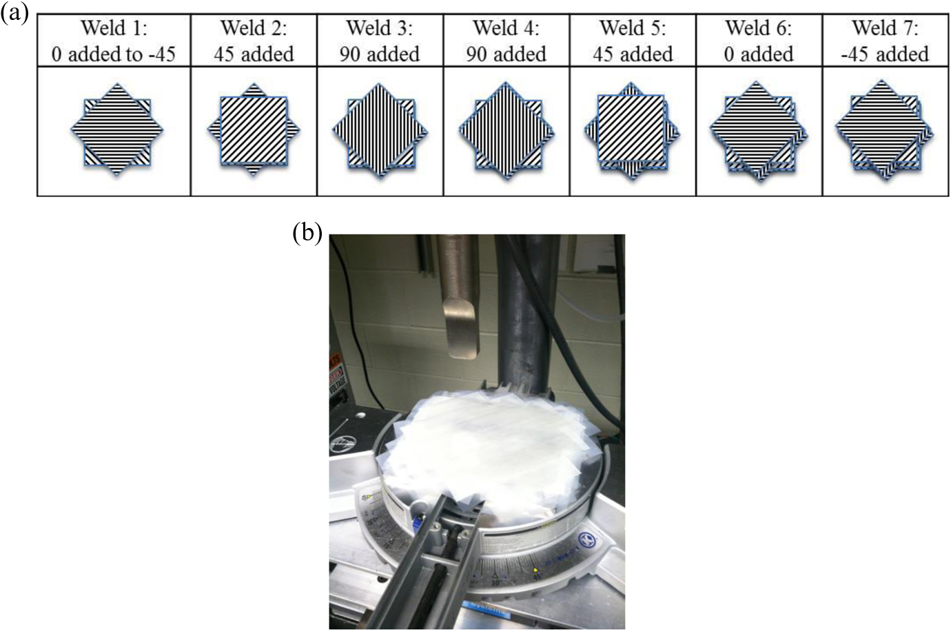
(a) Order of plies welded to fabricate eight-ply quasi-isotropic panel and (b) picture of a panel being welded in UC experimental setup. UC: ultrasonic consolidation.
The panels were then machined to smaller beam dimensions for flexural testing per ASTM D7264 standard. Since the eight plies of the quasi-isotropic specimen produced a significantly thinner sample than the unidirectional beam experiments, smaller beam specimens were fabricated, as indicated in Table 2. Note that the unidirectional samples were built up into laminates that were thicker than necessary and machined down to the proper thickness per the ASTM D7264 standard. As a result, even though the unidirectional laminates were initially made from 16 plies and the quasi-isotropic laminates were produced from 8 plies, the test specimen thicknesses are only 0.6 mm different. The different production methods are not an issue, since the unidirectional samples are not directly compared to the quasi-isotropic samples.
Transient through thickness temperature
An additional experiment was conducted to measure real-time temperatures of the first weld layer T1 during ultrasonic bonding to better understand transient thermal behavior of the material during the layering process and compare results with a simple analytical model. As illustrated in Figure 7, the specific test of a 11-layer unidirectional laminate involved sequential welding HDPE/glass plies using WTS-3 parameters, shown in Table 1, as a type-K thermocouple (shown as a black dot) was added between layers 1 and 2. The thermocouple was monitored using a USB-TEMP 8-channel data acquisition device and TracerDAQ data logger software scanning at 2 Hz.
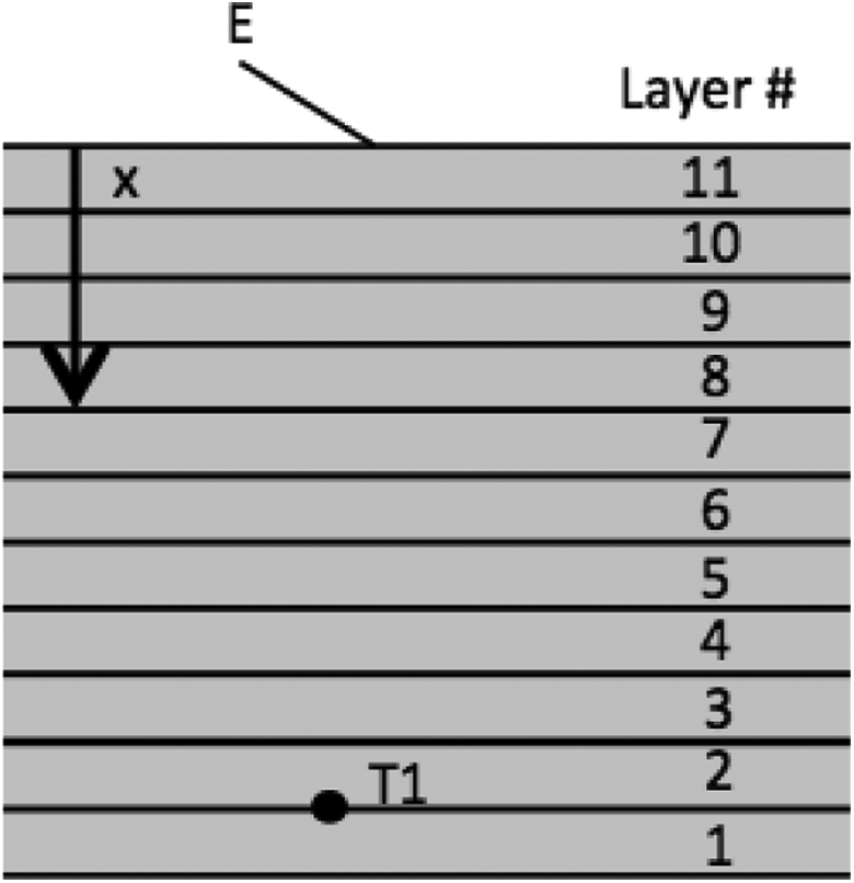
Thermocouple placement and unsteady conduction representation (side view).
To estimate temperature rise in the laminate as an ultrasonic horn moves over the surface and transfers heat, the unsteady conduction heating process is modeled as a semi-infinite solid subjected to a surface energy pulse.
35
Referring to Figure 7, the resulting temperature response, T, as a function of time, t, and depth, x, is
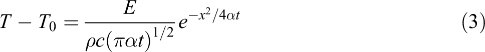
where T0 is the starting temperature of the composite, E is the energy per unit area (in J/m2) of the surface energy pulse at t = 0, ρ is the density, c is the specific heat capacity, and α is the thermal diffusivity. Typical thermal properties of the HDPE/glass and PET/carbon constituent materials gathered from a variety of sources are provided in Table 3. The effective density and thermal conductivity of the composite in terms of constituent properties (subscripts ‘f’ and ‘m’ used for fiber and matrix, respectively) and fiber volume fraction, Vf, are estimated by using the rule of mixtures and inverse rule of mixtures, respectively, as
Typical thermal properties for constituent materials and thermoplastic composite.
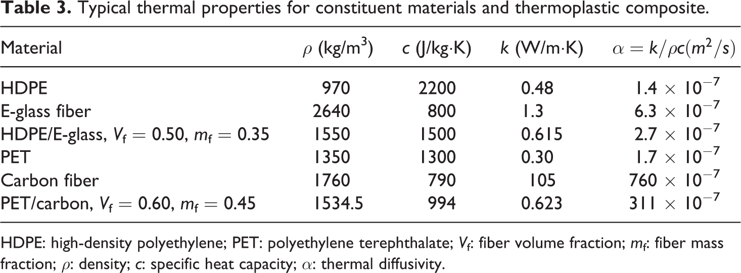
HDPE: high-density polyethylene; PET: polyethylene terephthalate; Vf: fiber volume fraction; mf: fiber mass fraction; ρ: density; c: specific heat capacity; α: thermal diffusivity.

Similarly, the effective specific heat capacity of the composite in terms of constituent properties and fiber mass fraction, mf, is estimated using the rule of mixtures as:
Experimental results
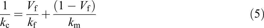
Table 4 shows the number of replicates tested, average flexural secant modulus, and average maximum flexural stress, σfm, for each specimen type. Similar to Young’s modulus, E, the flexural secant modulus,
Flexural secant moduli and maximum flexural stress for various types of composite specimens.
FA: frequency amplitude; WTS: welding traverse speed; FA: frequency amplitude; PET: polyethylene terephthalate; U/S: ultrasonics.
Ef secant: flexural secant modulus; σfm: maximum flexural stress.
To obtain σfm and
From Table 4, the strength and stiffness of HDPE/glass composite specimens consolidated ultrasonically are affected by welding speed and FA. Stiffness was slightly affected (20% decrease), whereas strength dropped 40%, as speed was tripled. The low-speed welding clearly afforded the best welds among the ultrasonic specimens, which is intuitive because it affords the highest energy transfer. FA has a minor effect on both stiffness and strength, although there is a minimum threshold (90%) for obtaining an acceptable bond with these sets of conditions. Thermal pressing resulted in nearly doubling both the stiffness and strength suggesting that UC process parameters are either not optimized or properties of the fiber (e.g. low thermal conductivity compared to carbon) may not be conducive to effective ultrasonic welding.
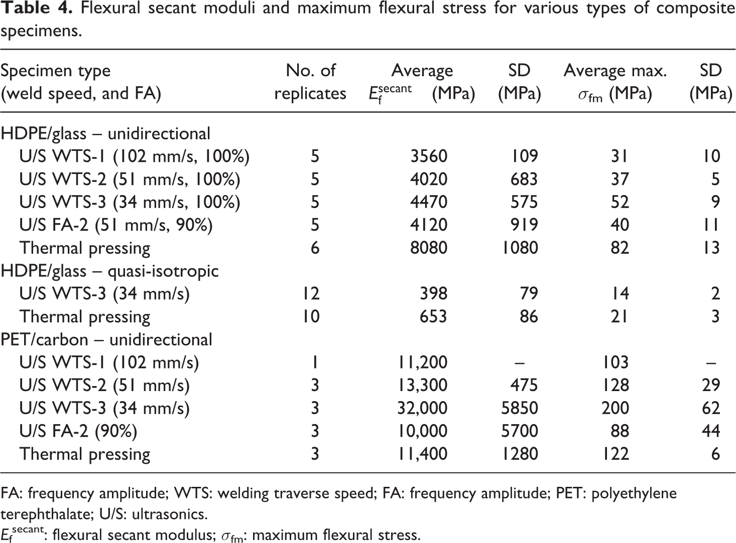
Strength and stiffness of ultrasonically consolidated PET/carbon composite specimens are similarly affected by welding speed and FA, although values are significantly higher than HDPE/glass. Stiffness dropped by 65% and strength dropped 49% as speed was tripled. It should be noted that stiffness data for the low welding speed (34 mm/s) have very high variation. Unlike the HDPE/glass results, an increase in FA (90 to 100%) resulted in a 33% increase in stiffness and 45% increase in strength. What is most interesting with PET carbon material is that the stiffness and strength values of ultrasonically consolidated samples increased by factors of 2.8 and 1.6, respectively, compared to thermal pressing. One possible explanation is that the carbon fibers efficiently distribute heat throughout the laminate during thermal pressing, whereas ultrasonic welding energy is focused primarily at lamina interfaces resulting in higher temperatures at these locations. This effect is seen in temperature versus time data for ultrasonic welding shown in Figure 8.
Weld 1 temperature versus time data.
Results of the thermal transient experiments and model used (Equation 3) for the first weld are shown in Figure 8. Thermal properties used in the model are found in Table 3. From the temperature versus time curves, it is clear that the model and the experimental data and trends are very consistent, at least close to the weld surface, even though the model includes many simplifications. The average difference in temperature between the predictive model and the experimental data, shown in Figure 9, indicates that the five middle five welds show the most deviation between the model and the experiment. These data do not show the individual deviations for each weld, so it does not tell the whole story. As a means of showing the differences in welds 2–4 and welds 5–10, the temperature versus time chart for welds 3 and 7 are shown in Figure 10. Additional testing will need to be completed to confirm these results.
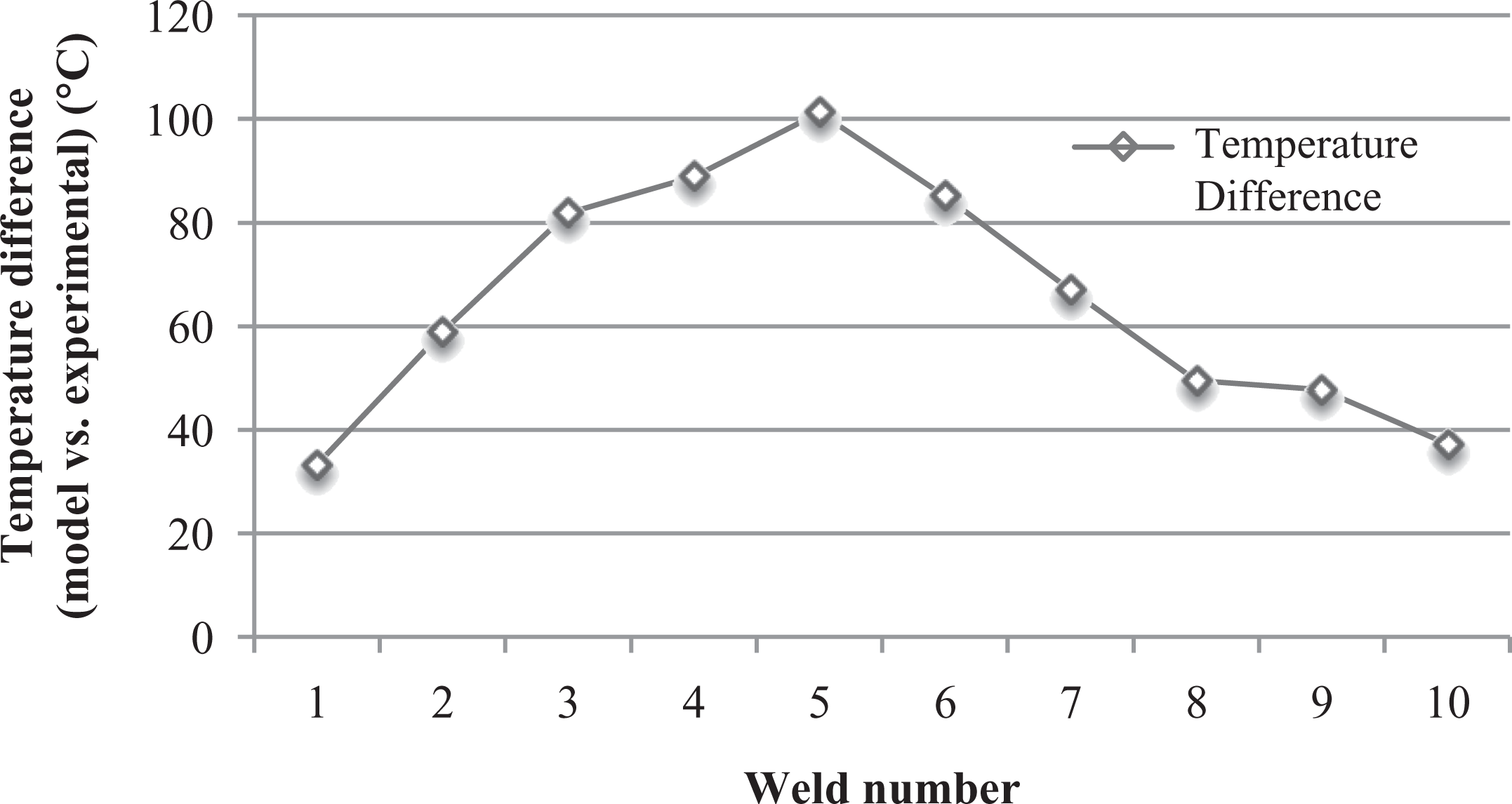
Temperature difference between model and experimental for each weld (weld number indicates layer interfaces in Figure 7 moving upwards from layer 1).
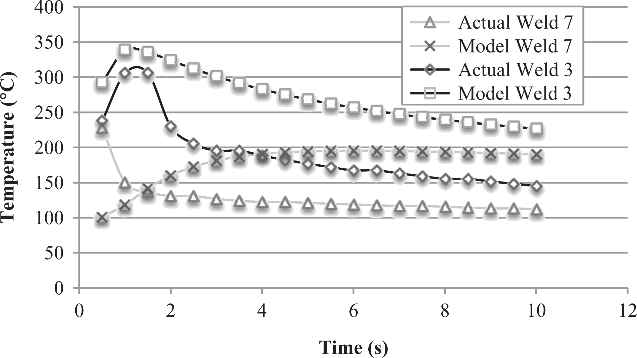
Temperature versus time for welds 3 and 7.
The data shown in Figure 10 show the general trends for the welding temperature versus time data. Welds 2–4 have similar shapes to weld 3, while welds 5–10 more closely resemble weld 7. The weld 3 model shows much promise in accurately describing the temperature changes, as it is even able to capture the initial peak. The only issue is that steady-state model temperature is roughly 50°C higher than the experimental data. This could possibly be due to heat lost back into the horn, or into the stage. Despite this difference, the general trend is similar. The model appears to deviate around weld 5, when the data appear much like weld 7 in Figure 10. The deviation in the shape of the trend is a result of the distance from the measurement point. In the model, there is an x2 term in the exponent, which results in more of a log-like trend than a decaying trend. The maximum deviation in the model is shown at weld 5, as indicated in Figure 9. This is a result of the steady-state portions of the model and actual data being far off. In reality, the model predicts the temperature rise much worse for welds 7–10, but the model is predicting a smaller temperature rise and the laminate only cools to a certain amount, leading to a smaller difference. The experimental data start high and level out at a lower temperature, while the model predicts a lower temperature to start, with a higher steady-state value. This could be due to the fact that the ultrasonic welding is being idealized as a surface energy pulse, which is not exactly correct; ultrasonics affect layers below the weld surface as well, which is not accounted for in the model. There are losses that are not accounted for in the model (through the build stage, back into the horn, etc.), and a 20% reduction in input energy shows a very good fit to the actual weld data for weld 1. Fortunately, the temperature at the weld surface closest to the horn is more important information for process understanding and optimization.
Conclusions and future work
The overall goal of this experimental study to was mimic AFP conditions and compare the mechanical properties of thermoplastic composite prepreg laminates bonded by UC to standard thermal pressing. Strength and stiffness for thermally pressed HDPE/glass specimens were both significantly higher those bonded by UC. The difference is attributed to non-optimized UC process parameters and material properties that may not be conducive to ultrasonic welding. Increased welding speed for UC reduced strength and stiffness, whereas a 10% change in FA did not. Quasi-isotropic specimens were only made using HDPE/glass tape and results were similar to the unidirectional specimens. On the contrary, stiffness and strength for UC PET/carbon samples were significantly higher than those made by thermal pressing. Increased welding speed and decreased FA, both of which reduce the amount of energy transferred to the weld, expectedly reduced both strength and stiffness.
The surface energy pulse model with material properties estimated using the rule of mixtures and inverse mixtures predicts temperature just below the weld surface (one ply away) relatively well, although less so deeper into the laminate. Despite many simplifications, the model can be useful in determining if the ultrasonic energy applied will heat the prepreg up to a desired temperature or possibly exceed it for process design and optimization.
Additional work is planned to demonstrate the use of UC for AFP. First, a test to show the possibility of using ultrasonics on layups that have gentle curves in the Z direction would be very important. Another useful test would be to check the effects of different UC frequencies on the resulting layups. The differing frequencies may allow for different composites to be used. The effects of larger ultrasonic horns should be shown to indicate how adaptable ultrasonic welding might be for larger scale layups. Finally, UC of more composite systems, especially higher temperature matrices such as PEEK, will be investigated.
Footnotes
Acknowledgments
The authors would like to thank Mr Dave Hauber at Automated Dynamics, Inc. for providing thermoplastic prepreg material and technical advice.
Declaration of Conflicting Interests
The author(s) declared no potential conflicts of interest with respect to the research, authorship, and/or publication of this article.
Funding
The author(s) received no financial support for the research, authorship, and/or publication of this article.