
Abstract
Composites have gained wide acceptance because of their unique properties. Drilling is a prerequisite operation for composite materials to form assemblies. Poor hole quality can affect tensile strength, structural integrity in long-term usages. The parameters to predict machinability of a good-quality hole are lower specific cutting energy, minimum drilling-induced damages like peel up at entrance and push out delamination. In this article, effect of different tool geometries, speeds and feeds are investigated during drilling on a composite plate having different chemical composition for specific cutting energy, peel up at entrance and push out delamination. A series of experiments was established based on the techniques of Taguchi. Statistical tools like signal-to-noise ratio, the analysis of variance and regression analysis are used to investigate effect on specific cutting energy and delamination. Conclusions show that proper selection of tool and cutting parameters influence specific cutting energy and delamination.
Introduction
The versatile polymer materials such as unsaturated polyester and vinyl ester-based composites find wide applications in aerospace, construction, transportation, infrastructure and industrial process equipments. Owing to its superb corrosion resistance properties, fibre-reinforced plastic (FRP) has displaced other more costly metals in many industrial process equipment such as tanks, piping, duct and hood systems, reaction vessels. Composite materials possess superior properties such as high stiffness to weight ratio, high strength to weight ratio, variable directional strength properties, thermal insulation, corrosion resistance, low specific gravity and high damping capacity.
Although the physical and mechanical properties of the advanced composite materials made them an attractive family of material, they have many problems related to machining compared to corresponding metallic materials. One of the problems is related with the fibres used as reinforcement. Their abrasiveness causes faster tool wear and deterioration of machined surfaces. 1 Besides that, composites machining can cause several damages like delamination, fibre pull-out, matrix thermal degradation and others. 2 Strategies adopted for successful machining of a composite plate depend more on the reinforcement than on the matrix material. 3 Generally composites are fabricated for near-net shape, thus reducing the machining needs to a minimum. However, some operations like drilling are usually performed in composite industries to enable structural assembly. Among all the damages that can occur in the drilling of a composite plate, delamination is the most serious, as it can cause loss of mechanical strength of the laminate plates. 4 In fact, it has been pointed that in aeronautical industries, 60% of part rejections are due to drilling-associated damages. 5 Drilling is a complex operation characterized by the existence of extrusion and cutting mechanisms, the former executed by the drill chisel-edge and the latter by the rotating cutting edges of the drill.
A considerable amount of research has been done to reduce delamination, based on adequate selection of cutting parameters, tool geometry and tool material. This involves study of effect of different stacking sequence of the fibre material on delamination factor, study of compatible coupling agent for a particular matrix and their %wt concentrations, surface fracture analysis, delamination study using artificial neural network (ANN), effect of process parameters, drill bit geometry and drill material. Davim et al. 6 studied the drilling of glass fibre-reinforced laminates manufactured by hand lay-up concluding that thrust force increases with feed rate, which is the cutting parameter that has a stronger influence. They showed that the damage increased when higher cutting speeds and feeds were used and that cutting speed has a greater influence on the damage in these materials. Mishra et al. 7 have used ANN to predict the drilling-induced damage on unidirectional glass fibre-reinforced plastic. ANN was used in predicting the presence of embedded delamination (in terms of size, shape and location) in FRP composite laminates using natural frequencies as indicative parameters.
Khashaba et al. 8 studied the effects of the drilling parameters such as speed and feed on the required cutting forces and torques in drilling chopped composites with different fibre volume fractions. Three speeds, five feeds and five fibre volume fractures were used in the study. The results showed that feeds and fibre volumes had direct effect on thrust force and torque. On the other hand, increasing the cutting speed reduced the associated thrust force and torque, especially at high feed values. Using multivariable linear regression analysis, co-relating empirical formulae were developed. The influence of cutting parameters on peel-up delamination and push out delaminations of the composite surfaces were investigated. No clear effect of the cutting speed on the delamination size was reported, whilst the delamination size decreased with decrease in the feed. Delamination free drilling of chopped composites with high fibre volume fraction was reported as a problem for further investigation.
Dura et al. 9 studied delamination during drilling of carbon/epoxy plates using the finite element method. The composite plate was modelled by successive layers, allowing the usage of different stacking sequences. The tool was modelled as a rigid body and different tool geometries were compared with axial thrust force and delamination on set. The simulation model considered non-linear, three-dimensional analysis for finite element composite interface and involved a damage model based on fracture mechanics.
El-Sonbaty et al. 10 studied the influence of cutting parameters on the thrust force, torque and surface roughness in drilling of fibre-reinforced composite materials. The parameters included were cutting speed, feed, drill size and fibre volume fraction. The quasi-isotropic composite materials were manufactured using randomly oriented glass fibre-reinforced epoxy and with various values of fibre volume fractions (V f) by hand lay-up technique. Two-component drill dynamometer was used to measure the thrust and torque during the drilling process. The dynamometer was connected with a data acquisition system and a computer. This set-up enabled to monitor and record the thrust force and torque with the aid of a computer program using Lab View utilities.
Machining of composite materials is an area full of open questions as studied by Hocheng and Puw relative to chip formation and assessment of machinability as compared to metal cutting. 11 A study of drilling of reinforced thermoset and thermoplastics for characterizing their responses to machining was presented. The results were discussed in comparison with the theories of metal cutting. First of all, the chip characteristics were observed and found to reveal various cutting mechanisms of these two materials. Calculation of the specific cutting energy provided information of the effort and size effect in machining of composite materials. Thermoset-based material required a larger cutting force due to higher strength and was more responsive to chip size because of the sensitivity to micro defects in fracturing chips. The results were useful in establishing a mathematical model to predict torque and thrust in drilling of composite materials as a function of cutting parameters and material strength. The effect of cutting conditions on cutting force as well as surface integrity of the hole at entrances, exit and at the walls were investigated. Based on the above discussions, some aspects of chip characteristics and machinability of these materials were revealed.
Rosario et al. studied the energy required during the dry drilling of PEEK GF30, a thermoplastic material, polyether–ether–ketone, reinforced with glass fibre. 12 Three different types of drills were used with reference to materials and geometry. Nine cutting conditions were selected based on cutting speeds of 6000, 7000 and 8000 r/min and feed rates of 300, 400 and 500 mm/min. Similar results were obtained for two types of drills, namely wolfram carbide with coating of TiAlN y and wolfram carbide with diamond point. First type of drill has economic advantages over the second one. An analysis of variance (ANOVA) shows that the type of drill is a more influential factor and the optimum conditions are with the tool made of WC with diamond point under the higher cutting conditions of speed and feed rate.
Hocheng et al. studied the machinability aspects for thermoset-based and thermoplastic-based composites with high- and low-fibre loading. 13 The experimental observations are discussed with reference to chip characteristics and specific cutting energy to reveal the mechanism of removal of material. It is concluded that the material fracture due to the brittle reinforcement as well as the level of fibre loading and the deformation behaviour of matrix polymer determine the extent of plasticity in chip formation and the chip length. The discussions of machinability are based on drilling force, surface roughness and edge integrity affected by cutting conditions (feed rate and cutting speed), drill geometry and lay-up system. An optimal domain of cutting parameters is suggested for secured machinability.
The emergence of new high-performance thermoplastics to replace thermoset in FRP puts up a new challenge, that is, their machining. In this study, carbon fibre-reinforced polycyclic butylenes terephthalate laminates were manufactured, drilled and inspected. 14 Different commercial drill geometries and machining conditions were compared. Roughness, microscopy and non-destructive tests were used to determine the hole quality as well as delamination. The surface tests showed that better results were obtained at the cutting speed of 3000 r/min which was commonly used than at high speed (15,000 r/min) with a constant feed rate. The result is explained on the basis of viscoelastic properties of the matrix that becomes fragile at high cutting speeds. The delamination factor obtained by means of ultrasonic and X-ray computed tomography also confirmed that the best results were achieved with a Twist drill bit at 3000 r/min. In contrast to carbon fibre-reinforced thermoset, the detected delamination at high cutting speeds was not as remarkable as expected. These results were used to conclude that the new composite would certainly increase production rate without delamination damage. Chip formation also plays a special role. The chips can be recovered and reused as reinforcement in manufacturing processes due to the recyclability of the thermoplastic matrix.
Titanium/graphite hybrid composites (TiGr) exhibit a potentially enabling technology which satisfies the low structural weight fraction and long operational lifetime required for the high-speed civil transport. TiGr composites are made of thermoplastic polymer matrix composite plies sandwiched with titanium foils as the outer plies. 15 The two materials are assembled by bonding the polymer matrix composite plies and titanium foils to form a hybrid composite laminate. Both experimental and analytical work was performed to characterize major hole-quality parameters and cutting mechanisms encountered in drilling of TiGr composites. The effects of consolidation processing, such as induction heating press and autoclave processes, on drilling characteristics of TiGr composites were examined. The hole-quality parameters and hole exit damage were investigated and discussed.
A thermoplastics-based composite material possesses better machinability. The work done by Hocheng and Puw reveals the machinability of carbon fibre-reinforced acrylonitrile–butadiene–styrene (ABS) in drilling compared to representative metals and thermoset-based composites. 16 The observation of chips reveals that considerable plastic deformation is involved. Compared to the chip formation of thermoset plastics, it contributes to the improved edge quality in drilling. The edge quality is generally fine except in the case of concentrated heat accumulation at tool lips. Heat is generated by high cutting speed with low feed rate. Plastics tend to be extruded out of the edge rather than neatly cut. The average surface roughness along hole walls is commonly below 1 μm for all sets of cutting conditions. In the experiment, the values between 0.3 μm and 0.6 μm were typically observed. The high-speed steel drill showed minor tool wear during the tests. Based on these results, it was concluded that the carbon fibre-reinforced ABS demonstrated good machinability in drilling.
Experimental work
Essentially, traditional experimental design procedures are too complicated and not easy to use. A large number of experimental work have to be carried out when the number of process parameters increase. To solve this problem, the Taguchi method uses a special design of orthogonal arrays to study the entire parameter space with only a small number of experiments as studied by Yang and Tarng. 17 Taguchi methods 18–20 have been widely utilized in engineering analysis and consist of a plan of experiments with the objective of acquiring data in a controlled way to obtain information about the behaviour of a given process. The greatest advantage of this method is the saving of effort in conducting experiments, saving experimental time, reducing the cost and discovering significant factors quickly. Taguchi’s robust design method is a powerful tool for the design of a high-quality system.
In this research work, an approach based on the Taguchi method is used for the entire series of experimental work. Statistical tools like signal-to-noise ratio (S/N ratio), ANOVA and regression analysis are employed to determine the desired optimum drill tool geometry and drilling process parameters for minimizing specific cutting energy and delamination at entry and exit for the composite plate of two different chemical structures. These techniques also predict percentage contribution of the factors involved. Finally, a confirmation experiment is conducted to verify the optimal process parameters obtained from the parametric design.
Chemical composition of composites
A high-grade mechanical dough moulding compound (DMC) and a high-grade electrical DMC compound is prepared using unsaturated polyester resin. The chemicals used and their parts by weight composition are shown in Tables 1 and 2, respectively. 21
Chemicals for mechanical grade composition-A.
Chemicals for electrical grade composition-B.
A plate of size 100 × 100 × 8 mm3 thick is prepared using above two formulations by compression moulding process. Their chemical composition is shown in Table 3. A medium viscosity and medium reactive isophthalic unsaturated polyester resin AROPOL IN 5334 from Ashland Inc. is used. It has good mechanical properties and good temperature resistance. It is also recommended for composite parts for corrosive environment. The chopped E-glass fibres strands from Owens Corning having specification EC 14 6 mm 979 are used as reinforcement. The specification stands for electrical grade, continuous glass fibres of 14 μm diameter, 6 mm in length and 979 stands for company’s code for sizing system. Fine precipitated calcium carbonate having crystal structure is used as filler. It has 99.9% purity and 95–99% Hunter brightness. The coupling agent used is Silquest A174NT having a methacryloxy functional trimethoxy silane from Momentive Performance Materials Inc. It finds utility in coating, composites, adhesives and sealant systems that cure via a free radical mechanism.
Chemicals and composition for both composites.
Drill tool details
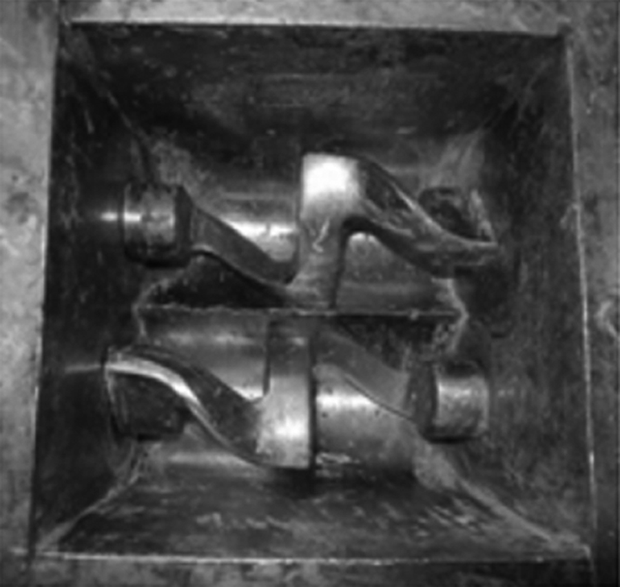
A 10-mm diameter drill tool is used for drilling the composite plate. It is made of solid carbide material having a flute length of 60 mm. Overall length is 100 mm with helix angle of 30°. Three drill tools having point angles as 80°, 100° and 118° are selected. These drills are shown in Figure 1.
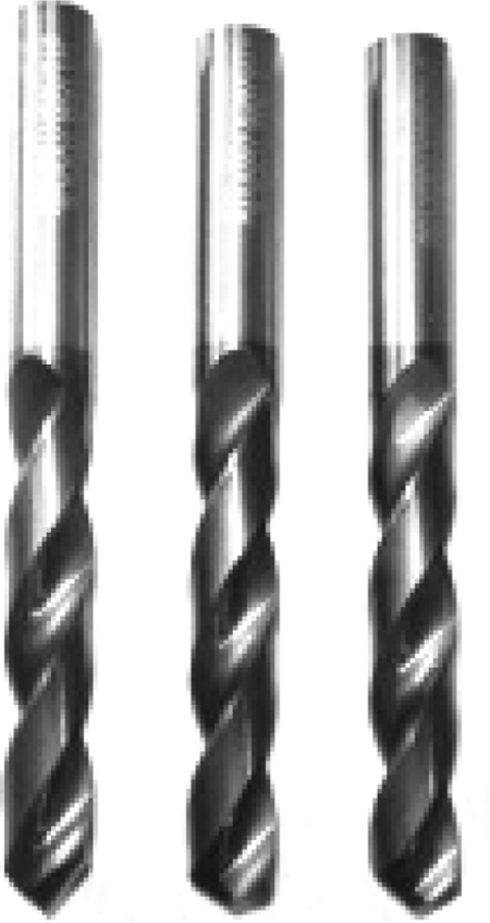
Drill tools with different point angle.
Delamination factor and specific cutting energy
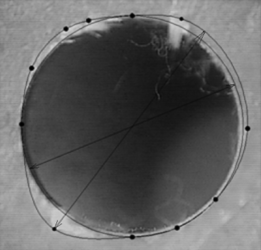
Quality of a hole in composites is decided by observing drilling induced damages like push out delamination, peel-up at entrance, intralaminar cracking, fibre/matrix debonding and thermal damage or matrix burning, chipping, etc. Among these, delamination is recognized as the most critical as it affects tensile strength of material, structural integrity and deterioration of properties in long-term performance. It is defined as ‘the separation of the layers of a material in a laminate’. It is accounted by the factor called as delamination factor which is defined as ratio of maximum diameter of the damaged zone around the hole to actual diameter of the hole. This delamination occurs at the entry and at the exit of the drill into the composite plate. This is shown in Figure 2.
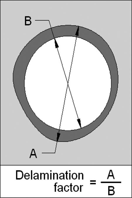
Delamination factor.
One of the factor which describes efficiency of any cutting process is ‘specific cutting energy’ (SCE) and is defined as the total energy input rate divided by material removal rate and depends on the material, chip cross-section and tool geometry. 11 The best drilling process would be having minimum energy consumed and high metal removal rate. Energy required to drill a hole can be measured by energy meter. The material removal rate (MRR) in drilling is the volume of material removed by the drill per unit time. For a drill with a diameter D, the cross-sectional area of the drilled hole is πD 2/4. The velocity of the drill perpendicular to the work piece f (mm/s) is the product of the feed fr and the rotational speed N where N = V/πD. Conversion of feed rate fr (mm/rev) to feed rate f (mm/s) is f = N × fr (mm/min).
Thus,
SCE in joule per cubic milliletre is given by following equation
Experimental equipment
The DMC is prepared in a Sigma mixer. The Sigma mixer consists of two counterrotating tangential rotors in a W-shaped trough, curved at the bottom to form two longitudinal half cylinders. Close clearance is maintained between the blades and the walls of the mixer resulting in a perfectly homogeneous mix. The tangential action of mixing and kneading is thoroughly obtained by two ‘Z’-shaped kneading blades, which rotates very accurately towards each other causing the product to be transferred from one blade to the other simultaneously. The compression moulding machine used is 10 ton, four pillar transfer moulding hydraulic press from Plus One Machinefabrik. Figures 3 and 4 show the Sigma mixer and the compression moulding machine used for manufacturing the composite plate. The computerized numerical control (CNC) milling machine used is ARGO 2 S vertical milling machine. The composite plate is clamped to the machine bed at two ends with the help of a strap clamp. The CNC milling machine and the clamping arrangement of composite plate are shown in Figures 5 and 6.
Sigma mixer.
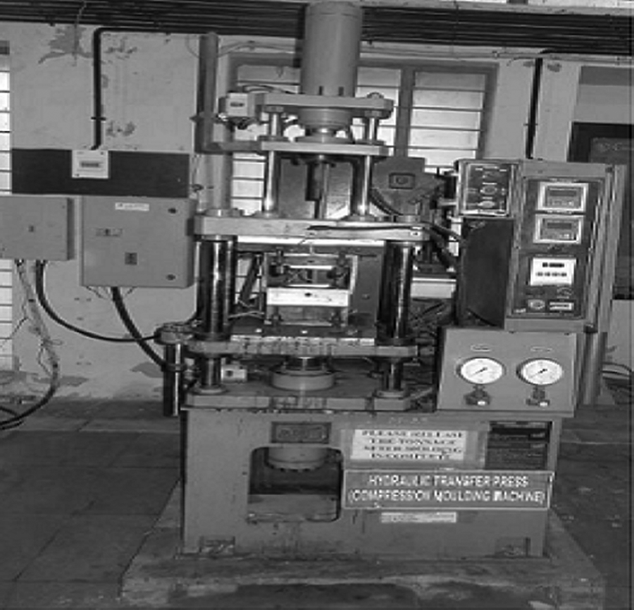
Compression moulding machine.
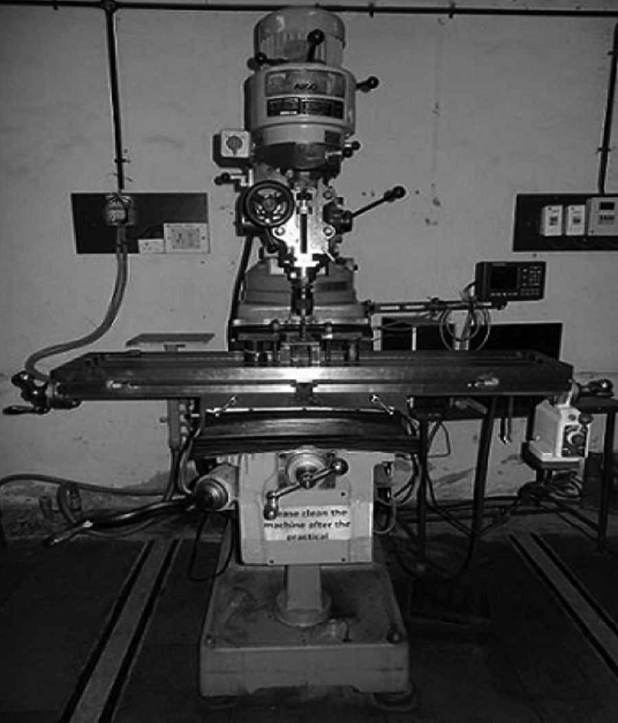
ARGO CNC milling machine. CNC: computerized numerical control.
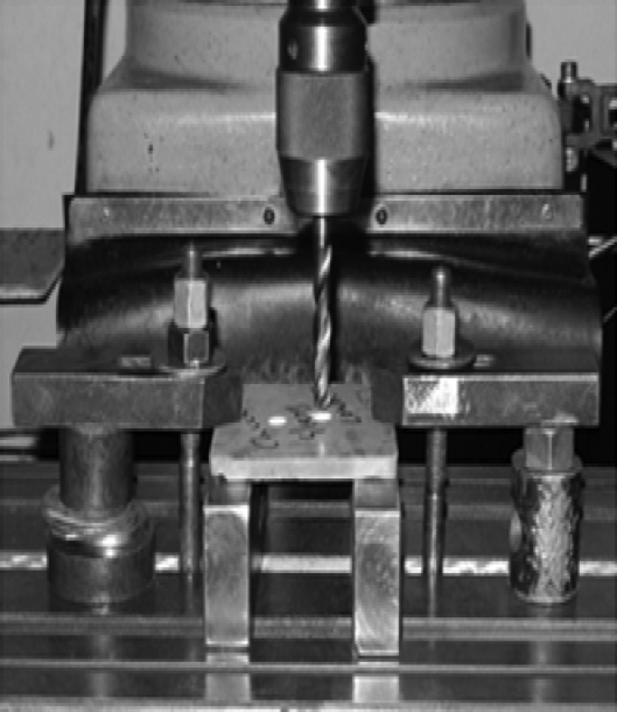
Drilling set-up for the plate.
All the drilled holes are studied for delamination at the entry and at the exit surface under Carton Stereo Microscope, Japan. The model number of the microscope is SPZ-50PFM having 6.7–50× zoom and illumination source is 9 W fluorescent light. A typical delaminated hole and the actual hole as observed through the Carton Stereo Microscope is depicted in Figure 7.
Delamination of hole as observed through Carton stereo microscope.
In order to measure the energy during the drilling process, energy meter is coupled to the CNC machine. The energy meter used is NANOVIP PLUS which is a hand-held portable instrument of Decontrol widely used in power transmission systems and is used to measure power in the range of 7 W–150 kW accurately. It gives the values of voltage (V rms), current (A rms), P.F.cosø, active power (W), reactive power (var), apparent power (VA) and frequency (Hz). The coupling of energy meter to CNC machine and to the computer is shown schematically in Figure 8.

Block diagram showing coupling of energy meter to CNC milling machine and to the computer. CNC: computerized numerical control.
Experimental procedure
The known quantity of glass fibres is first fed to the rotating Sigma mixer for preparing DMC of particular composition. The coupling agent is then added whilst the blades in the mixer are counter rotating to have good bonding between the fibres and matrix. It is then followed by calcium stearate as lubricating agent and benzyl peroxide as catalyst. The dough so formed is then mixed with calcium carbonate filler and unsaturated polyester resin respectively. The dough is allowed to remain in a rotating mixture for 15–20 min till thorough mixing is achieved. Before mixing, the compression moulding machine is set at a temperature of 200°C and is left to reach the set temperature. The thoroughly mixed dough is then placed in the cavity of a heated compression mould and the core is brought slowly towards cavity to avoid spillage of material and then the mould is closed. The heating is achieved by means of cartridge heater placed in core and cavity of the mould. The mould is opened and closed 2–3 times for degassing and then the holding pressure of 145 kg/cm2 is applied. Due to heat and pressure, the dough is cured in the mould. To bring the mould to room temperature by cooling, the compression mould is provided with drilled hole channel for water to circulate. After the mould reaches the room temperature, the mould is opened and the composite plate is removed by the ejector pin provided in the core-half.
In order to quantify the effect of unsaturated polyester resin and chopped glass fibres on specific cutting energy and delamination, each composite plate is drilled at 6 places on a CNC milling machine with a drill bit size of 10 mm. The power consumed is measured with energy meter for each drilling and recorded in the computer. The average reading of the 6 drilled holes is considered as a final result. The specific cutting energy SCE is calculated using equation (1). During drilling, no coolant is used in the entire experimentation.
In order to measure the delamination of the drilled holes at the entry and exit surfaces, the composite plate is placed under the Carton Stereo Microscope. Out of the six holes drilled, the image of the maximum damaged hole at entry and the exit surface is captured. This damaged hole image in .bmp format is then imported in a computer aided designing (CAD) software and control points are located on the image. A spline is drawn around them to get the maximum damaged zone and the image is enlarged in the software so that actual diameter hole size is equal to 10 mm. The diameter around maximum damaged zone is recorded. The delamination factor as previously defined is ratio of maximum diameter of the damaged zone around the hole to actual diameter of the hole.
Taguchi method and design of experiments
The Taguchi method reduces the variation in a process through robust design of experiments. The overall objective of the method is to produce high-quality product at low cost to the manufacturer. Taguchi developed a method for designing experiments to investigate how different parameters affect the mean and variance of a process performance characteristic which defines how well the process is functioning. The experimental design proposed by Taguchi involves using orthogonal arrays to organize the parameters affecting the process and the levels at which they should be varied. For the given parameters, the Taguchi method tests pairs of combinations than all the possible combinations like in factorial design. This allows for the collection of the necessary data about the factors affecting product quality with a minimum amount of experimentation, thus saving time and resources. The two major tools used in the Taguchi method are the orthogonal array (OA) and the S/N ratio. OA is a matrix of numbers arranged in rows and columns. Each row represents the levels of factor in each run and each column represents a specific level for a factor that can be changed for each run. S/N ratio is indicative of quality. The Taguchi experimental method finds best level for each operating parameter so as to maximize or minimize the S/N ratio. The S/N ratio characteristics can be divided into three categories as follows:


where
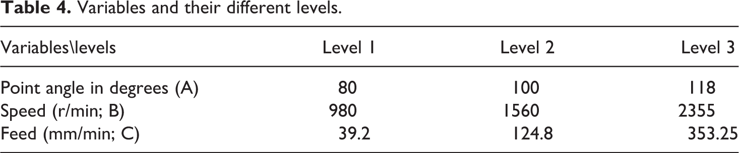
The general steps used in Taguchi method are as given below: 1. Step 1: In this step, the process objective is defined. For the present work, the process objective is to have minimum specific cutting energy and least delamination factor. Ideal target values would be zero for specific cutting energy and would be unity for the delamination factor. Hence smaller the better characteristics of S/N ratio are selected for both these process objectives. 2. Step 2: In this step, the variables that affect or control these process objectives and their levels are determined. Specific cutting energy and delamination are dependent on point angle of drill, cutting speed and feed. In this work, for these three variables that is point angle of drill, cutting speed and feed, three levels are selected as shown in Table 4.
Variables and their different levels.
The degrees of freedom (DOF) for three variables are calculated as below:
For point angle, DOF = 3 – 1 = 2; for speed, DOF = 3 – 1 = 2
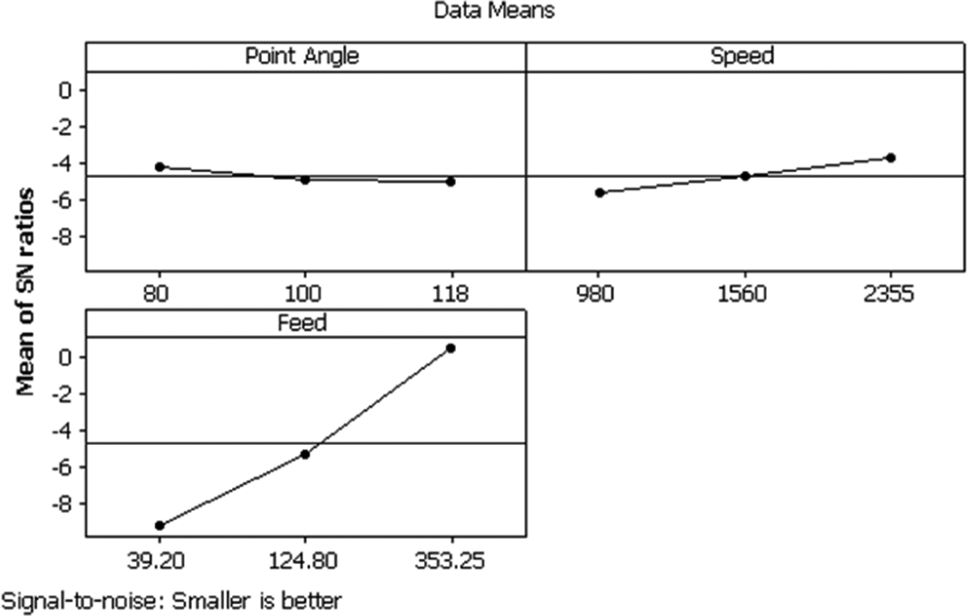
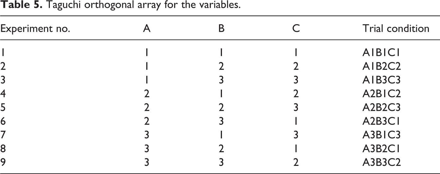
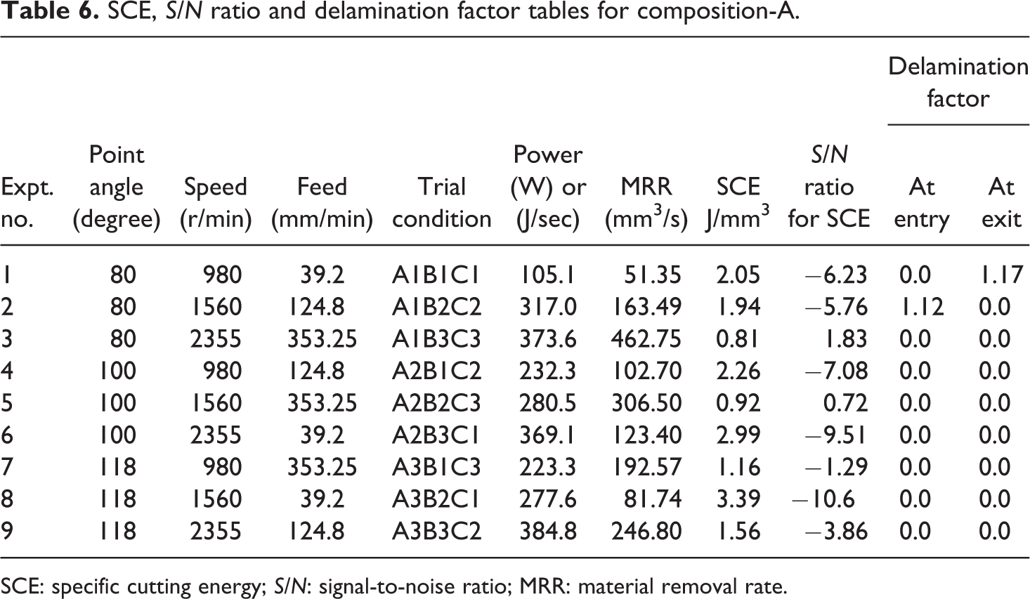
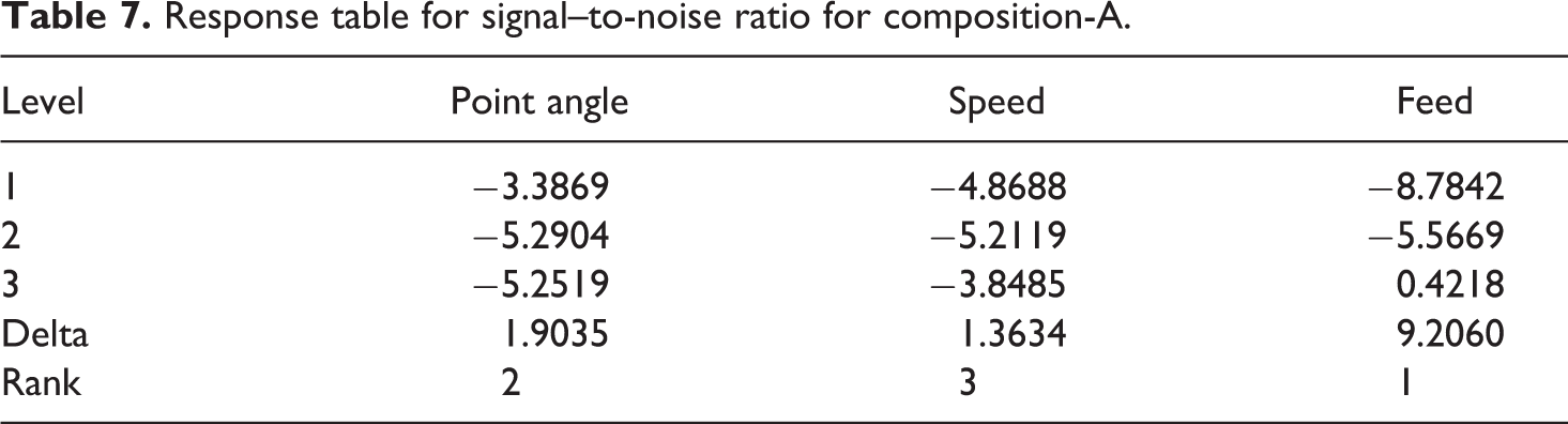
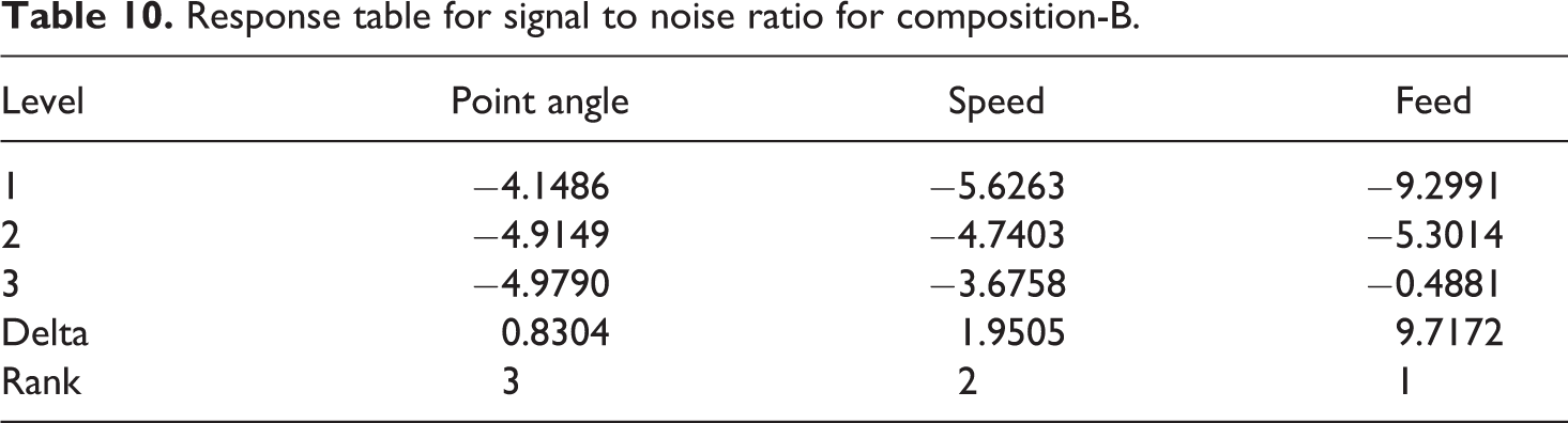
For feed, DOF = 3 – 1 = 2. 3. Step 3: In this step, suitable OA is selected based on number of variables and their levels. As per the Taguchi method, for 3 variables and their 3 levels, L9 orthogonal array (OA) is selected which has nine rows corresponding to the number of tests, with three columns at three levels. L9 orthogonal array has eight DOF, of which 6 are assigned to three factors (each one 2 DOF) and 2 DOF are assigned to the error. The tabulated L9 orthogonal array with its variable levels for 9 experiments is shown in Table 5. 4. Step 4: In this step, all experiments are conducted as per the variable levels indicated in Table 5 and the process objectives that is, SCE and delamination factor at entry and exit of the composite plate are noted for composition-A. The measured experimental results for SCE, delamination at entry and exit and S/N ratio calculations are shown in Table 6. Corresponding response table for signal to noise ratio is shown in Table 7 and the ANOVA calculations are shown in Table 8. The main effect plots for S/N ratio are shown in Figure 9. Minitab16 software is used for S/N ratio, ANOVA, and response for S/N ratio calculations. Regardless of the category of the performance characteristics, a greater S/N value corresponds to a better performance. Next all these experimentation and corresponding calculations are done for composition-B and the results are shown in Tables 9
to 11 and Figure 10. 5. Step 5: Multiple linear regression model: A multiple linear regression model is developed using statistical software Minitab version 16. This model gives the relationship between an independent/predicted variable and a response variable by fitting a linear equation to observe data. Regression equation thus generated establishes correlation between the significant terms, namely point angle of drill, speed and feed obtained from ANOVA analysis.
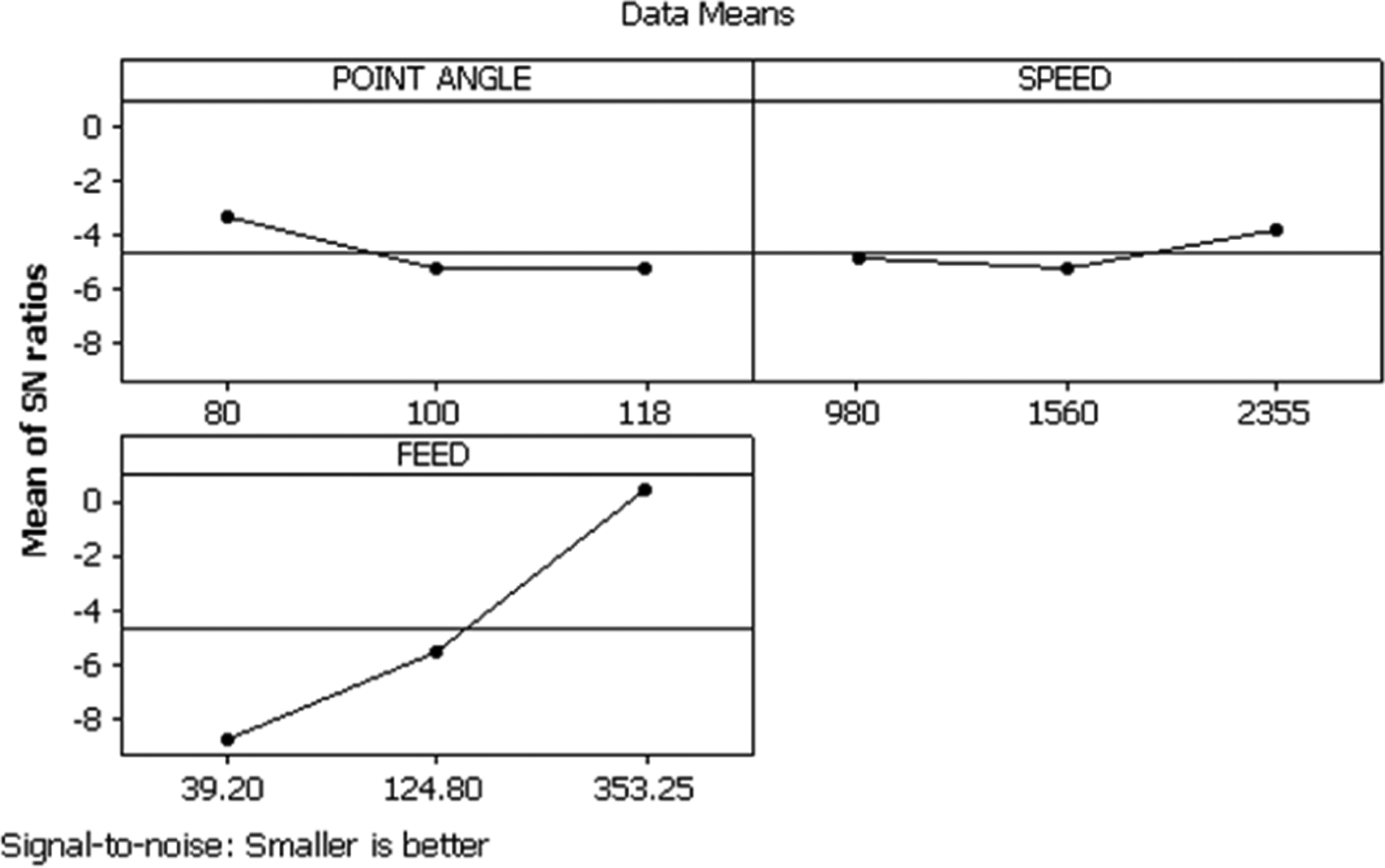
Main effects plots for S/N ratio for composition-A. S/N: signal-to-noise ratio.
Main effects plots for S/N ratio for composition-B. S/N: signal-to-noise ratio.
Taguchi orthogonal array for the variables.
SCE, S/N ratio and delamination factor tables for composition-A.
SCE: specific cutting energy; S/N: signal-to-noise ratio; MRR: material removal rate.
Response table for signal–to-noise ratio for composition-A.
ANOVA table for composition-A.
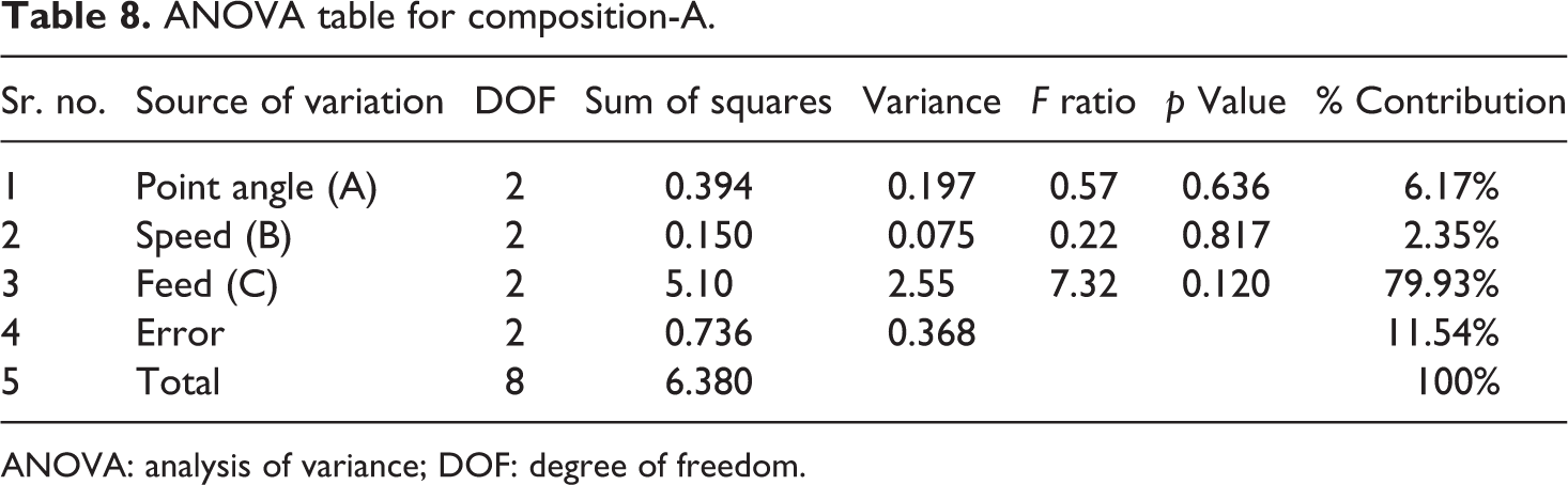
ANOVA: analysis of variance; DOF: degree of freedom.
SCE, S/N ratio and delamination factor tables for composition-B.
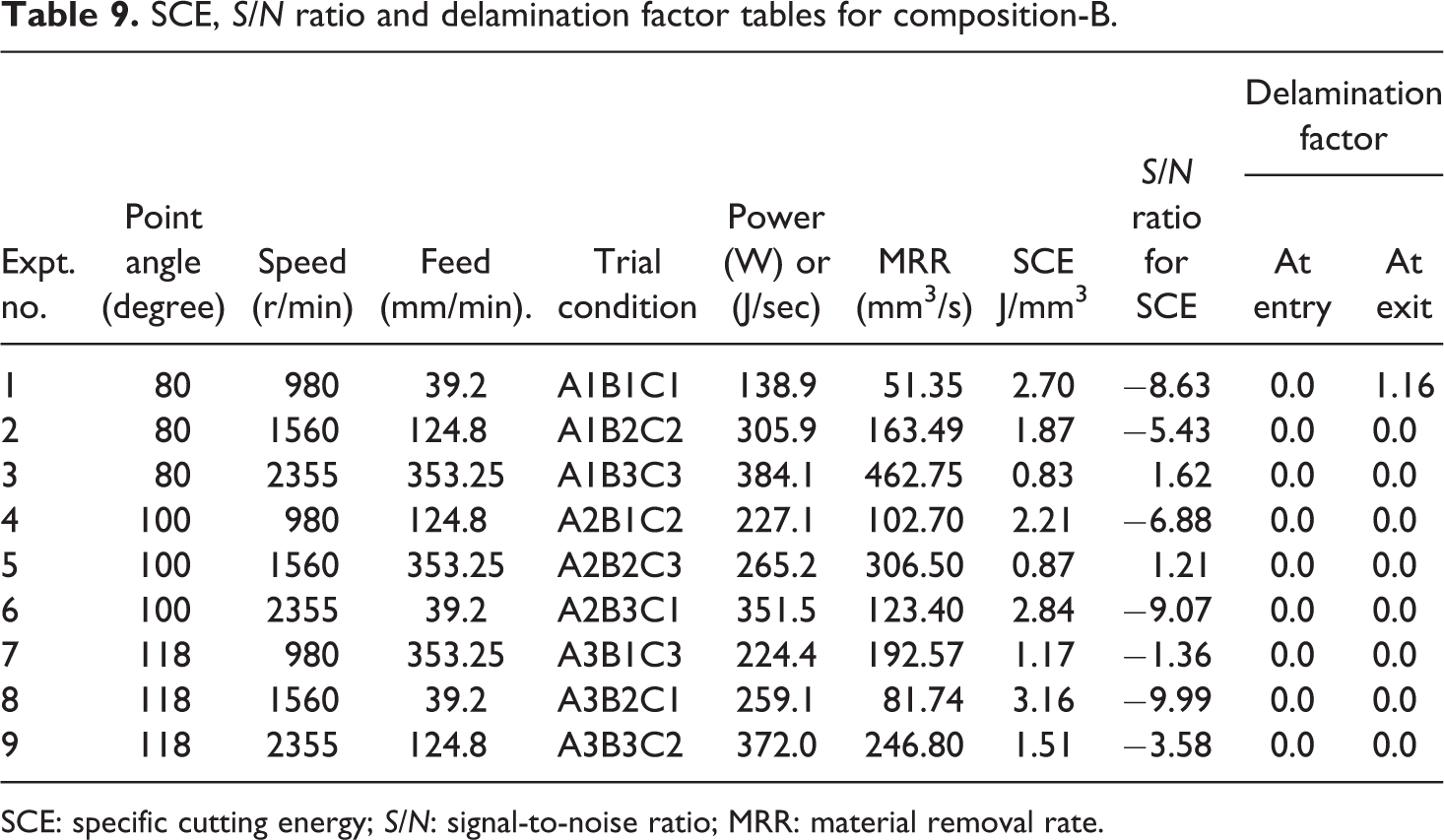
SCE: specific cutting energy; S/N: signal-to-noise ratio; MRR: material removal rate.
Response table for signal to noise ratio for composition-B.
ANOVA table for composition-B.
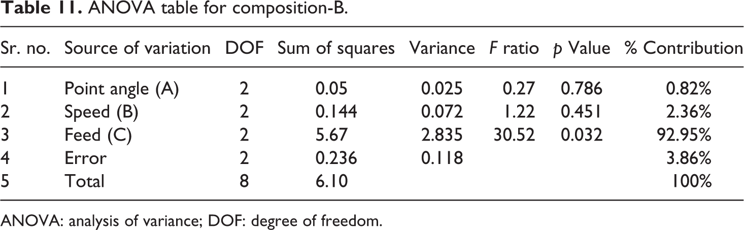
ANOVA: analysis of variance; DOF: degree of freedom.
The regression equation developed for composition-A is as follows:

The regression equation developed for composition-B is as follows:
6. Step 6: Confirmation test:
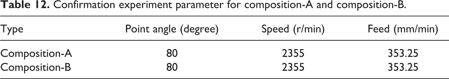
The experimental confirmation test is the final step in verifying the results drawn based on Taguchi’s design approach. The confirmation experiment is a crucial step and is highly recommended by Taguchi to verify the experimental results. Confirmation experiment is carried out by utilizing levels of optimum process parameters of A1B3C3 that is, point angle of 80°, cutting speed of 2355 r/min, and feed of 353.25 mm/min for both the compositions as they correspond to greater S/N value. Confirmation experiment parameters for composition-A and composition-B are shown in Table 12.
Confirmation experiment parameter for composition-A and composition-B.
Conclusions
Chemically different structure like mechanical-grade composition-A and electrical grade composition-B have been investigated using Taguchi method for drilling parameters. Effect of drill point geometry, speed and feed of drilling has been studied on these two structures. The following conclusions can be drawn from the investigations: For mechanical-grade composition-A: Minimum power is consumed using point angle of 80°, speed of 980 r/min and feed of 39.2 mm/min that is, at smallest point angle and lowest speed and feed. Faster material removal rate is achieved by using smallest point angle, highest speed and feed but at a cost of higher power consumption. Hence for the better efficiency of machining that is, for the combined effect of these two parameters as indicated by SCE it is advisable to use smallest point angle of 80°, highest speed of 2355 r/min and feed of 353.25 mm/min. The lowest specific cutting energy recorded is 0.81 J/mm3. The main contribution factor is feed (79.93%) followed by point angle (6.17%) and speed (2.35%) as indicated by response for S/N ratio and the ANOVA calculations tables. The delamination factor is found to be zero for most of the point angle, speed and feed combination. The other values obtained are negligible and can be ignored. For electrical grade composition-B: For this grade, the minimum power consumption, higher material removal rate and SCE results are similar to that of a mechanical grade composite. The lowest specific cutting energy recorded is 0.83 J/mm3 using smallest point angle of 80°, highest speed of 2355 r/min and feed of 353.25 mm/min. The main contribution factor is feed (92.95%) followed by speed (2.36%) and point angle (0.82%) as indicated by response for S/N ratio and the ANOVA calculations tables. The delamination is negligible at all observations. It is observed that as the E-glass fibre content is increased, more power is consumed at optimum processing condition of point angle of 80°, speed of 2355 r/min and feed of 353.25 mm/min. This is in accordance with the fact that shear force is directly proportional to glass fibre content of the composite. And hence, more energy is consumed in shearing them. Also addition of the calcium carbonate filler in mechanical grade reduces the shear force and hence the shearing energy. Confirmation experiment is carried out and the results of confirmation experiments and linear regression model as obtained from equations (2) and (3), respectively, are compared and are tabulated in Table 13. The study shows an error associated with specific cutting energy in both composites varying from 20.12% to 21.68%. Thus design of experiments by Taguchi method was successfully used to predict the SCE behaviour of both the composite types. The influence of all factors has been identified and it is believed that the results could be a key factor in helping engineers in composite fabrication field in determining optimum machining process parameters. This research approach can be augmented to thermoplastic composites as they find wide applications due to their properties such as improved impact resistance, damage tolerance and higher moisture resistance. During machining, thermoplastic composites behave entirely different from thermoset in many aspects because of differences in their viscoelastic properties. Thermoplastics demonstrate large plastic deformation capability under loads, while thermosets are brittle. Such behaviour influences material response to machining.
Confirmation experiment result comparison for composition-A and composition-B.
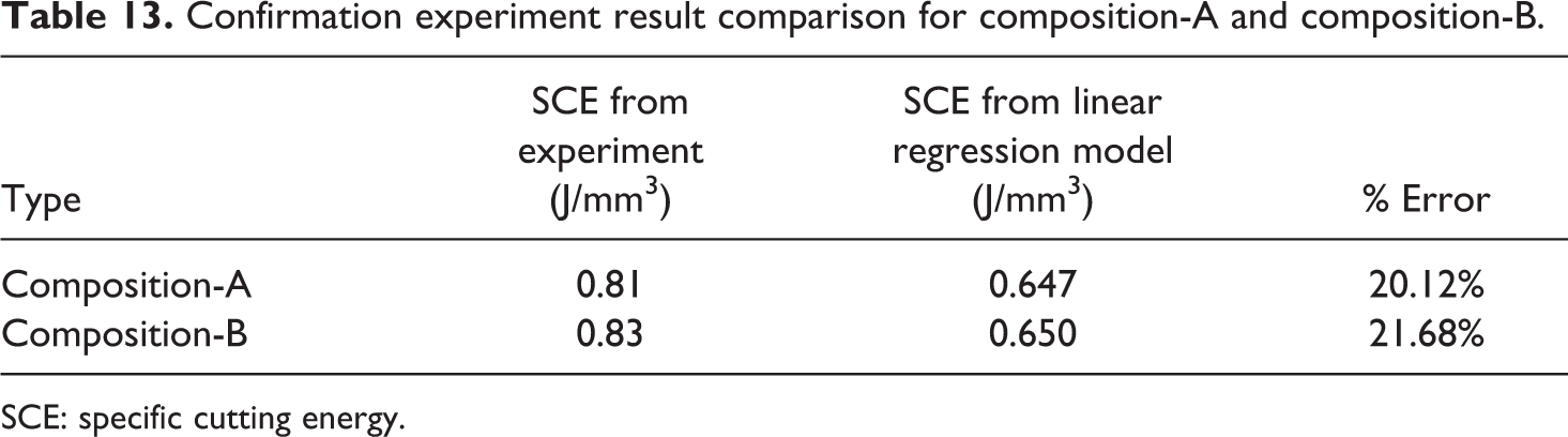
SCE: specific cutting energy.
Footnotes
Acknowledgements
We thank Metatech Industries, Pune, Maharashtra State, India, for providing facilities of Carton Stereo Microscope, Japan, for delamination inspection.
Declaration of Conflicting Interests
The author(s) declared no potential conflicts of interest with respect to the research, authorship, and/or publication of this article.
Funding
The author(s) disclosed receipt of the following financial support for the research, authorship, and/or publication of this article: The authors would like to express deep thanks to the Department of Polymer Engineering of Maharashtra Institute of Technology, Kothrud, Pune 411038, Maharashtra State, India, for funding the work.