
Abstract
Mixed-mode fracture characteristics of epoxy-based biocomposite reinforced with 20 wt% walnut shell particle and 10 wt% coconut fibres are investigated. The biocomposite is fabricated using the squeeze casting method. The positive aspect of hybrid combination of fibre and particle reinforcement is advocated by comparing mode I, mode II and mixed-mode I/II fracture surfaces under a scanning electron microscope. An edge-cracked semicircular arc specimen subjected to symmetric three-point bend (TPB) loading is suggested for fracture toughness testing of biocomposite material. A series of fracture tests are conducted on hybrid biocomposite using the proposed semicircular bend (SCAB) specimen geometry, TPB and four-point bend (FPB) specimens. The average mode I and II fracture toughness obtained from semicircular arc bend (SCAB) specimen are 1.319 MPa and 1.219 MPa
Introduction
In recent decades, natural fibre-reinforced composites are getting much attention in structural application, automobile industries and household applications. Various works on the application of natural fillers and fibres like walnut shell, almond shell, pineapple, sisal, coconut shell and coir, jute, palm, cotton, rice husk, bamboo, wood, and so on as the reinforcements in composites have been reported in the literature. 1,2 A significant number of published studies have been dedicated to mechanical and thermal properties. 3 However, because a flaw-free material is extremely difficult to be produced and cracks may be introduced during service, understanding the crack resistance ability is thus essential. Good toughness and crack-stopping capability are particularly important. It has been mentioned that toughness of a brittle thermosetting polymer such as polyester and epoxy can be improved through natural fibre reinforcement. 4 However, fracture toughness studies of biocomposites have received relatively little attention from the scientific community until now. Due to increasing demand of biocomposites in various applications, it is envisaged that the fracture toughness of biocomposites will play a vital role over the coming years. It is known that biofibres- or bioparticles-reinforced epoxy-based biocomposites are prone to brittle fracture under mechanical loading. Compared with metals, the application of fracture mechanics concepts to polymers and composites is still in the primitive stage. In the polymer field, in spite of some controversies, the fracture toughness tests meant for homogeneous materials are used to determine KIC and J-integral. 5,6 In these studies, the employed procedures are similar to those applied to metals, as described by ASTM D5045 standards. 7
Among the published works on biocomposites, only few researchers 8 –19 have studied the fracture properties such as toughness or critical stress intensity factors of biocomposites. Zamanian et al. 16 have investigated the toughness of epoxy polymers modified with a range of different nanosilica particles using three point bend (TPB) specimen and concluded that addition of nanosilica particles improves the toughness of the epoxy resin to a significant level. Silva et al. 17 characterized short sisal and coconut fibre composites as well as sisal fabric composites using compact tension specimens. It was found that increasing fibre content increased fracture toughness of the composites. At comparative fibre content, sisal fabric composite demonstrated better fracture toughness compared to short sisal fibre composite. The fracture toughness of jute and hemp laminates-reinforced polyester composites was investigated by Hughes et al. 4 It was found that hemp/polyester composite demonstrated better critical stress intensity factor and energy release rate. At 20% of fibre volume fraction, 313% and 870% improvement in fracture toughness and critical strain energy release rate was achieved for jute/polyester composite, respectively, whereas for hemp/polyester composite, the improvement was 466% and 1740%, respectively. Reis and Ferreira 18 in their work have analysed three different types of natural fibres, namely coir, sugarcane bagasse and banana fibres and concluded that coir and sugarcane bagasse fibres reinforcement improved the fracture toughness by 15.7% and 17.8%, respectively, compared with unreinforced epoxy concrete. However, 22.2% of deterioration in fracture toughness was found for banana pseudostem fibre reinforcement. Fracture energy was found to be improved for all types of natural fibres composites, where 100.8%, 15.9% and 41.1% improvement were achieved for coir, sugarcane bagasse and banana pseudostem fibre, respectively. Wonga et al. 19 have investigated the fracture behaviour of short bamboo fibre-reinforced polyester composites. Results of Wonga et al. 19 have indicated that the fracture toughness of all types of composites is higher compared to neat polyester. Maximum increment of 340% is achieved at 10 mm/50 vol% of fibre reinforcement. Also they have characterized that the toughening mechanisms involved are crack-tip blunting, crack deflection and crack pinning which lead to energy dissipation through matrix plastic deformation, fibre debonding, fibre pull out and fibre damage. Recently, authors 20 have studied the mode I and mode II fracture toughness behaviour of coconut fibre and walnut shell particle-reinforced hybrid biocomposite.
Epoxy-based composites are prone to brittle fracture under mechanical loading. Fractures are often initiated from pre-existing cracks or flaws embedded in the fibre or particle-reinforced composites after the manufacturing process or during the use. These flaws are usually oriented at an arbitrary angle relative to the loading direction. Therefore, the investigation of fracture resistance of epoxy-based hybrid biocomposites under mixed-mode loading is of great importance. The aim of this work is to develop a hybrid biocomposite material composed of epoxy resin and reinforced with walnut shell particles and coconut fibres. Semicircular arc bend specimen (SCAB) geometry along with TPB and four-point bend (FPB) loadings are used to determine the fracture toughness under different modes of loading. The results obtained from new SCAB geometry are validated with the results obtained from TPB and FPB specimen geometries by statistical significance test.
Materials and methods
The raw materials used in this study are walnut shell, coconut fibre, epoxy and hardener. Walnut shells obtained from the nearby market are first cleaned off dirt and impurities and then are chipped using a knife ring flaker. After that, the chipped shells are converted to particle form by Wily mill. The walnut shell particle sizes vary between 1.618 µm and 2.685 µm. Particles are oven dried at 100 ± 5°C for 15–20 min to reach the target moisture content (<2%) before using them as reinforcing material. The oven used in the study with the temperature range of 0–600 ± 1°C and proportional–integral–derivative-controlled specifications was supplied by M/s System Control (Chennai, Tamil Nadu, India). Coconut fibres are extracted from exocarp, washed with distilled water and dried at 100°C for 24 h. The length and diameter of coconut fibres used in the present investigation vary from 1.0 mm to 1.5 mm and from 5.441 µm to 10.673 µm, respectively. Araldite CY 230 epoxy resin is used as an adhesive in the preparation of biocomposite. HY-950 is used as the hardener. CY 230 and HY 951 are supplied by M/s Fine Finish Organics Pvt. Ltd (Chennai, Tamil Nadu, India). Epoxy resins, also known as polyepoxides, are a class of reactive prepolymers and polymers that contain epoxide groups. Reaction of polyepoxides with polyfunctional hardeners HY 951 forms a thermosetting polymer, often with strong mechanical properties. The ultimate tensile strength and modulus of elasticity of the epoxy CY 230 are 44.93 MPa and 1.633 GPa, respectively. 20 The biocomposite is fabricated by squeeze casting method. The detailed procedure of casting is described in the works by Singh and co-workers. 21 –23 The mould of size 300 × 250 × 10 mm3 is used for fabrication.
Fracture toughness test
TPB specimen
Figure 1 shows the TPB specimen under symmetrical loading. Mode I fracture toughness KIC under three-point bending is calculated using the following expression,

TPB specimen. TPB: three-point bend.
FPB specimen
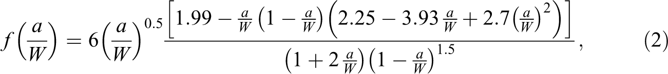
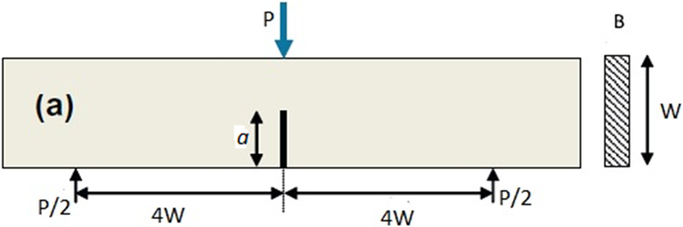
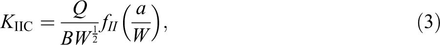
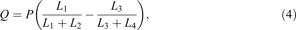
Single edge-notched FPB specimen shown in Figure 2 is used for mode II fracture experiments. The mode II fracture toughness KIIC under four-point bending is calculated using the following expression,
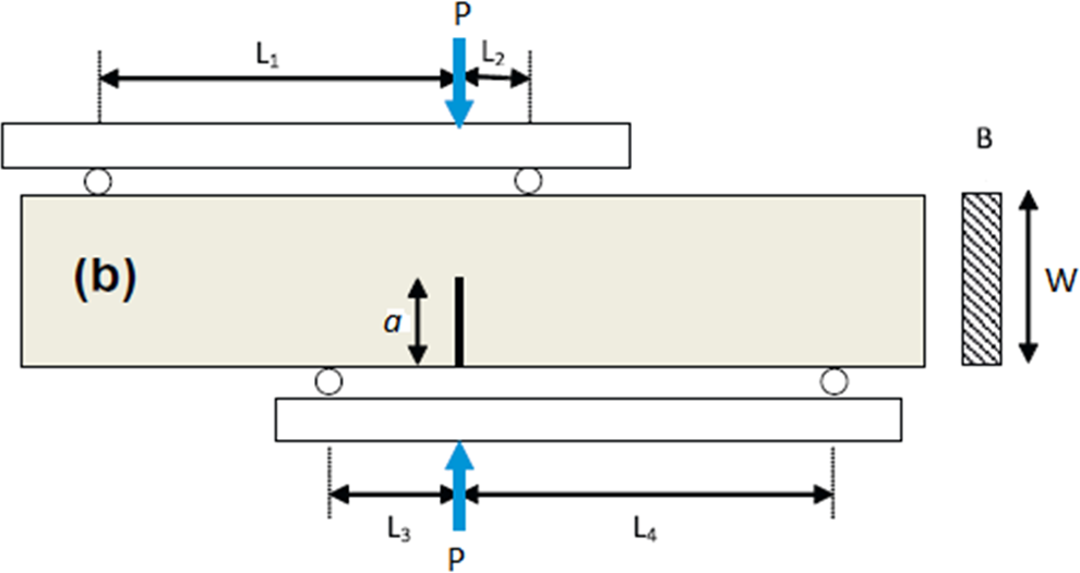
FPB specimen. FPB: four-point bend.
The geometry factor is determined from the following relation:

SCAB specimen
Semi circular bend (SCB) specimen configurations (Figure 3(a) and (b)) are suggested by different test standards for mode I, mode II and mixed-mode I/II fracture toughness test. In order to control the relative combination of modes I and II in the classical SCB specimen, one has to produce specimens with different crack inclination angles. One major drawback for the classical SCB specimen is related to the practical difficulties in producing an angled crack in the specimen, particularly for mode II dominant loading conditions in which the crack angle is relatively large (about 50°). The improved SCB configuration as suggested by Ayatollahi et al.
24
also requires a special loading set-up to produce different mode mixity. Special care is needed to adjust the different span lengths from the crack line or load line and may provide measurement error to a significant level. Because of such shortcomings in SCB specimen, a modified arc SCB specimen is proposed in this work to overcome the previous weaknesses. Among the specimen configurations such as classical SCB, modified SCB or Brazilian disc (BD) specimen, SCAB is also suitable for modes I, II and mixed-mode I/II test, and this type of SCAB specimen geometry can save more than 50% of the material as compared to SCB- or BD-type specimens. Figure 3 shows the comparison of three types of specimen geometry. Figure 3(c) shows the geometry and loading conditions for the proposed test configuration called the SCAB. In this test configuration, a semicircular arc specimen of width W that contains an edge crack of length a emanating normal to the inner curve surface of the specimen is loaded at the centre by a TPB fixture. Whilst the specimen is easily manufactured, it does not need complicated loading fixtures for using it in the conventional testing machines. The TPB fixture available with any conventional universal testing machine can be used without any modification or extra attachment. Moreover, the crack is always perpendicular to the tangent at the point of the crack. This simplifies the making of the angled crack. The SCAB specimen can also be used for mixed-mode test just by changing the location of the crack from the load line. Hence, different mode mixities can be obtained in the proposed specimen. The specimen can be used for the simple case of symmetric loading conditions in order to obtain pure mode I fracture toughness for several engineering materials. The finite element (FE) method is employed in this research to determine KI and KII. The stress intensity factors KI and KII for the SCAB specimen are functions of the crack length a, the specimen width W and crack inclination angle α with respect to the loading direction. This can be written as:


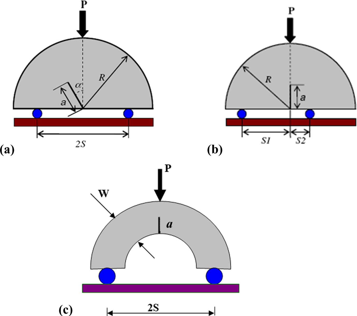
SCB specimen under TPB loading (a) with inclined crack (b) asymmetrical loading (c) SCAB specimen. SCB: semicircular bend; TPB: three-point bend; SCAB: semicircular arc bend.
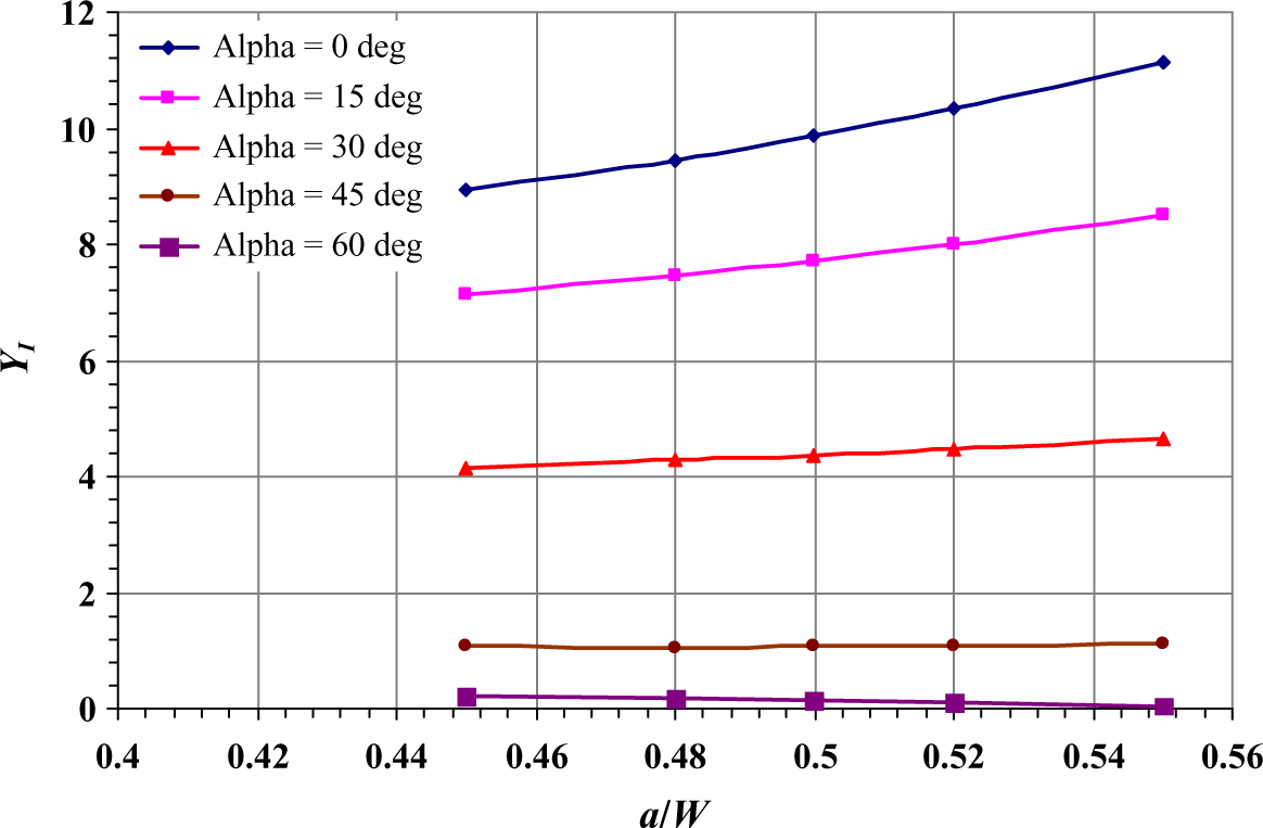
Variations of mode I geometry factor YI with a/W for different crack inclination angle (α). a: crack length; W: specimen width.
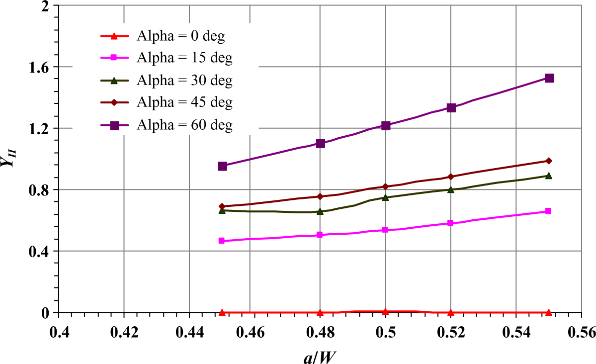
Variations of mode II geometry factor YII with a/W for different crack inclination angle (α). a: crack length; W: specimen width.
Fracture toughness tests are carried out at room temperature in an ADMET servo hydraulic universal test system (Norwood, Massachusetts, USA). For this purpose, single notched TPB, FPB and SCAB specimens (Figures 1, 2 and 3(c)) are employed for mode I, mode II and mixed-mode I/II fracture experiment. Specimens are prepared according to the dimensions shown in Figures 1, 2 and 3(c) from the 10 mm thickness board cast using different reinforcing materials described earlier. The mechanical slit is made at the required position (Figures 1, 2 and (3(c)) by means of a jewellery saw of 0.1 mm thin blade. After obtaining the required size of a mechanical slit, a sharp pre-crack is introduced in the bend specimen by lightly tapping a sharp new razor blade into the tip of the mechanical slit or notch. All the tests are carried out at 0.5 mm/min crosshead speed.
Figure 6 shows the loading set-up for the SCAB specimen geometry. The load–displacement data are recorded during the tests and are shown in Figure 7. All the test samples fractured suddenly from the crack tip and with negligible non-linear deformation show the brittle fracture behaviour of the tested samples. Using the fracture load obtained from each specimen, the stress intensity factors are calculated and the results are presented in Tables 1–3.
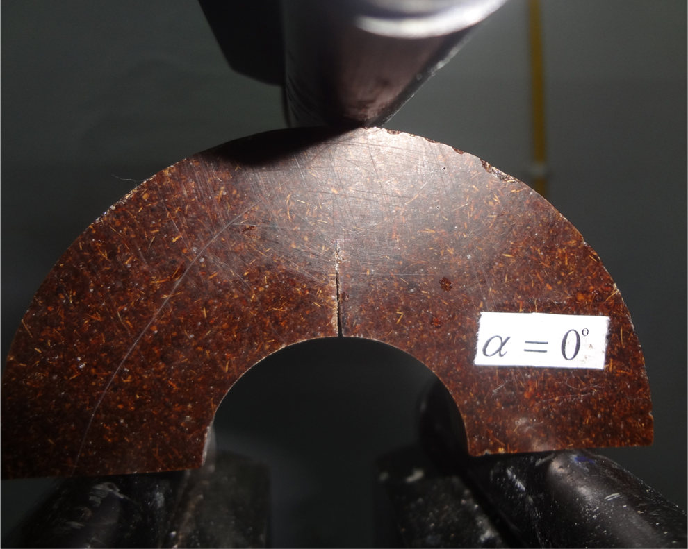
SCAB specimen geometry and loading set-up of walnut shell particle and coconut fibre-reinforced biocomposite. SCAB: semicircular arc bend.
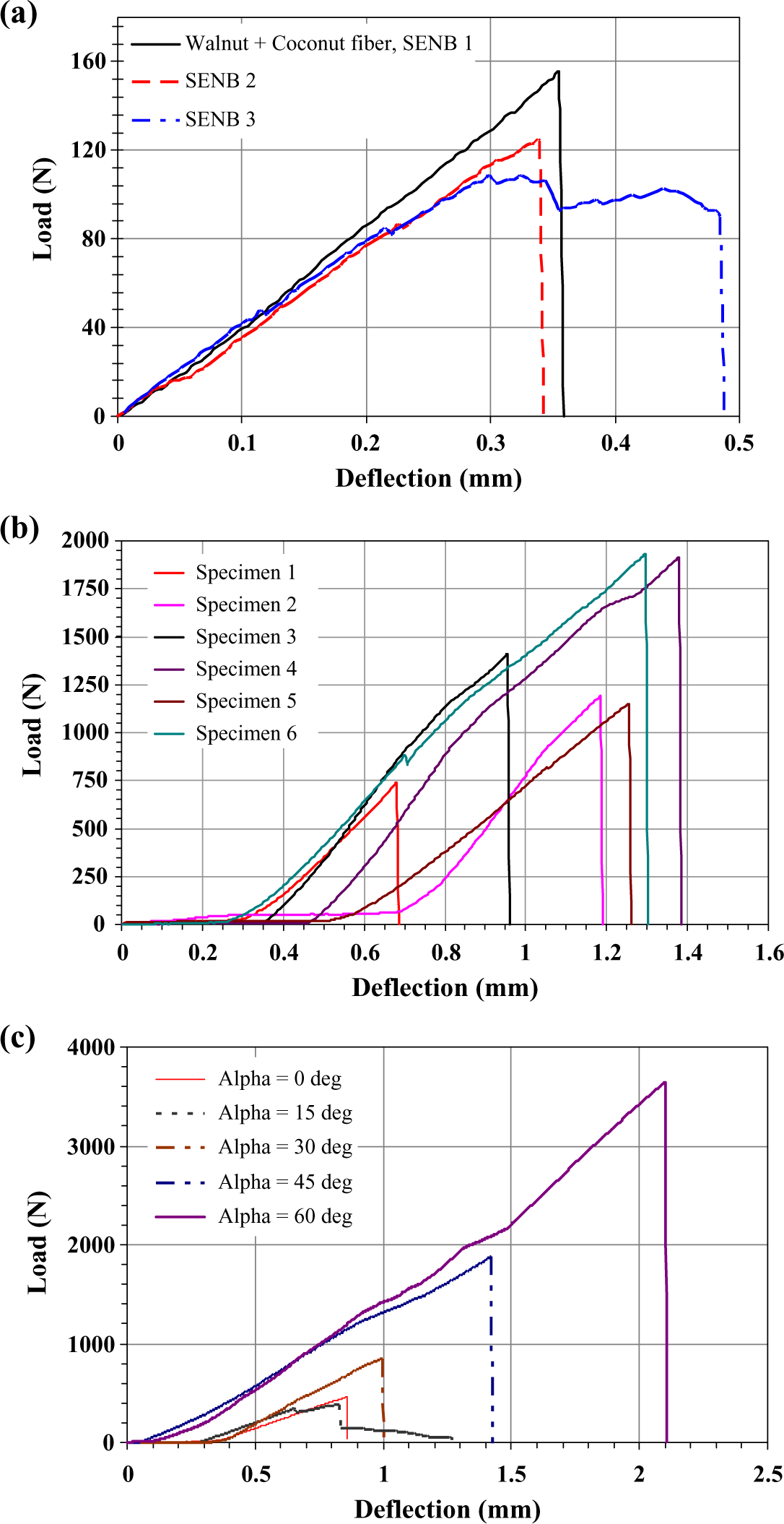
Load–deflection behaviour of coconut fibre and walnut shell particles-reinforced hybrid biocomposite under (a) three-point bending (SENB (b) four-point bending (c) semicircular arc bending (note: number 1, 2, …, etc mentioned in figures indicate specimen number (replication), alpha indicates crack inclination to the loading direction). SENB: single-edged notch bending.
Fracture load and mode I critical stress intensity factor with their mean and variance obtained from TPB and SCAB α = 0° specimens.
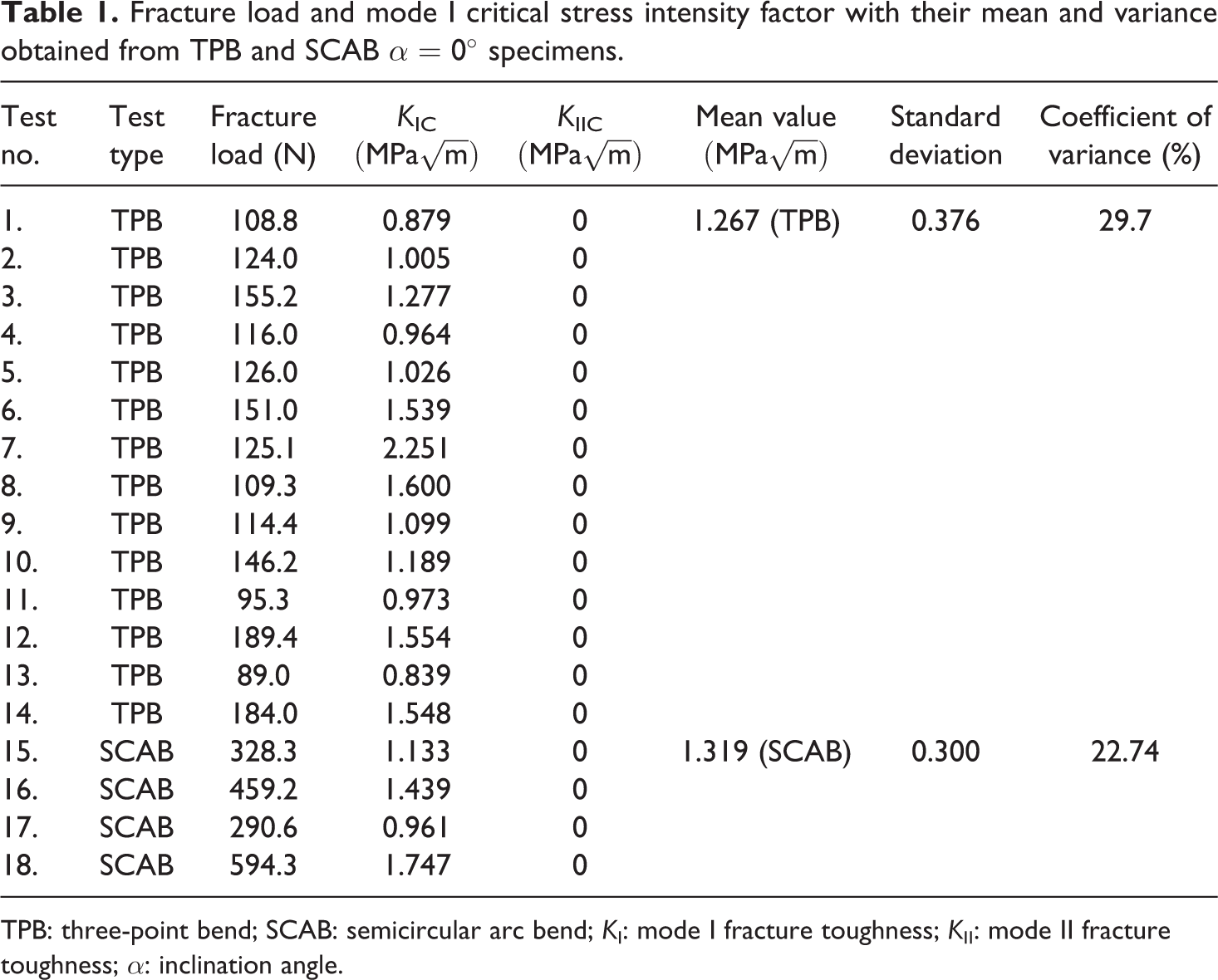
TPB: three-point bend; SCAB: semicircular arc bend; KI: mode I fracture toughness; KII: mode II fracture toughness; α: inclination angle.
Fracture load and mode II critical stress intensity factor and their mean and variance obtained from FPB and SCAB α = 60° specimen geometry.
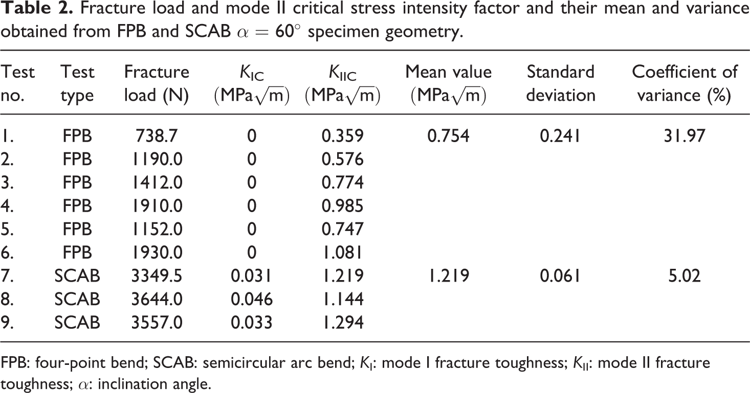
FPB: four-point bend; SCAB: semicircular arc bend; KI: mode I fracture toughness; KII: mode II fracture toughness; α: inclination angle.
The fracture toughness values of biocomposite material for different crack inclination angles obtained from SCAB specimen geometry.
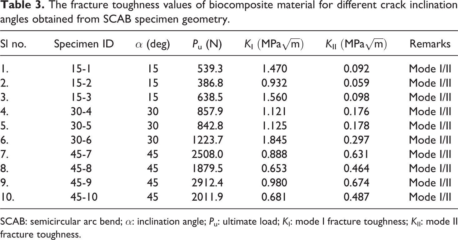
SCAB: semicircular arc bend; α: inclination angle; Pu: ultimate load; KI: mode I fracture toughness; KII: mode II fracture toughness.
Results and discussion
Mode I fracture toughness
In the present investigation, mode I fracture toughness (KIC) is determined from the TPB specimen and SCAB specimen with α = 0°, and the results are presented in Table 1. Fourteen tests under TPB and four tests under SCAB geometry are conducted. For three-point bending, all fracture toughness tests are conducted for the crack length a = 7.5 mm, width W = 15–15.5 mm and thickness B = 10 mm. The dimensions taken for SCAB geometry are B = 10 mm, W = 20 mm, 2 S = 40 mm and a = 10–10.5 mm. The load displacement curves under three-point bending and SCAB for α = 0°are shown in Figure 7(a) and (b), respectively. It is seen that curves rise in a linear way until their maximum value. An abrupt load drops off after attaining the maximum value describing the fracture behaviour under mode I loading. Under three-point bending, the failure load varies from 89.0 N to 189.4 N whereas under SCAB, the failure load varies from 290.6 N to 594.3 N. Thus, the values of KIC under the three-point bending are found to be varied between 0.839 MPa
Mode II fracture toughness
The mode II fracture toughness (KIIC) is determined from the FPB specimen and the SCAB specimen with α = 60°. The results are presented in Table 2. In four-point bending, different specimen dimensions of L1 = L4 = 20 mm and L2 = L3 = 10 mm, crack length a = 4–4.5 mm, thickness B = 10 mm and width W = 10 mm are taken. The geometry parameters of SCAB specimens are a = 10–10.5 mm, W = 20 mm, B = 10 mm and α = 60°. The load displacement curves are shown in Figure 7(b) and (c). Similar nature to mode I is seen in the variation of load displacement. In the four-point bending, the mean, standard deviation and coefficient of variance of KIIC are 0.754 MPa
Mixed mode (modes I and II) fracture toughness
The mixed-mode fracture tests are conducted on the SCAB specimens with different crack inclination angles, foe example, α = 15°, 30° and 45°. The force–displacement diagrams for α = 0°, 15°, 30° and 60° shown in Figure 7(c) are linear up to fracture. In calculation of mode I and mode II fracture toughness, the peak load in each experiment is considered. This is because the force–displacement diagrams are linear and fulfil all the requirements of ASTM standard. The mixed-mode fracture toughness values are determined using fracture load and geometry factors given in Figures 5 and 6 for SCAB specimen with different values of α. The results are presented in Table 3.
The mean values of KI and KII with their statistical properties are shown in Table 4 for biocomposite material. The coefficient of variance is found to vary between 15% and 26% under mixed-mode loading. The higher coefficient of variance is mainly due to inhomogeneity in the material and different failure mechanisms working together in particle and fibre-reinforced hybrid biocomposite. It is seen that as the crack inclination angle increases, the effective stress intensity factor also increases. However, for crack angle α ≥ 45°, the effective stress intensity factor decreases and the value became slightly less than the mode I fracture toughness. In the present investigation, optimum effective stress intensity factor is observed for α = 30°. It is also observed that the load-carrying capacity of mode II specimen increases drastically as compared to the mode I geometry. Even the specimen size in SCAB geometry is same for α = 0° and 60°, the load-bearing capacity with α = 60° is about 8.41 times more than α = 0°. This is because under mode I loading, the crack propagates along the direction of the load line, and hence due to opening of the crack most of the particles ahead of the crack tip are either pulled out or the crack moves around the particle making a curvature path. Under mode II condition, complete crack closure occurs and shear-induced effects become dominant. Under shear loading unlike normal loading, fracture does not take place along the initial crack and thus the chances of particle pull out is less as compared to mode I. During experimental work, it is observed for α = 60° that the closing of crack is started at a load level of 870 N and it closed completely when the load level reached 2000 N, and the specimen finally fractured at a load level of 3557 N. Thus, several mechanisms are working under such loading. Thus due to many toughening mechanisms such as crack bridging, crack curvature and shear-induced effects, more energy is needed and hence the load-bearing capacity under mode II is increased to a significant magnitude as compared to mode I.
Overall mean, variance and coefficient of variance of fracture toughness of 20 wt% walnut shell particle and 10 wt% coconut fibre-reinforced biocomposite.
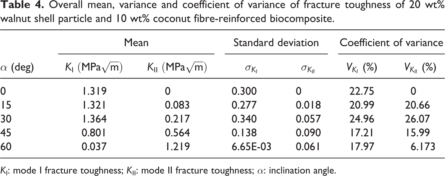
KI: mode I fracture toughness; KII: mode II fracture toughness; α: inclination angle.
Fracture toughness ratio
The ratio of KIIC over KIC obtained from TPB and FPB specimens, respectively, varies typically from 0.159 to 1.288. The mean value of the ratio is 0.595 for the investigated biocomposite material. However, from the experimental results of SCAB geometry, the ratio varies from 0.655 to 1.347 with a mean value of 0.924 which is closer to the maximum tangential stress (MTS) predicted value of 0.87. The overall ratio from the results of SCAB, TPB and FPB is 0.762 with a mean KIC = 1.294 MPa
Scanning electron microscope (SEM)
The reinforcement by incorporation of particles or fibres has been articulated as the result of strong interfacial bonding between the matrix material and the reinforcing elements either in the fibre form or in the particulate or hybrid form. Typically, the degree of bonding is also influenced by the dispersion of particles in the polymer matrix. A homogeneous dispersion will increase the effective particle polymer interfacial area and leads to the strong interaction. In addition, good dispersion also reduces large and dense particle agglomeration, which tends to act as defects, constituting stress concentrations under applied loads, which facilitate the triggering of micro-cracks and their progression to material failure. 20 Several toughening mechanisms of particle–fibre-reinforced composites have been reported in the literature. Some of the toughening mechanisms in epoxy matrices are crack path deflection, 28,29 plastic deformation, 30 –32 crack front pinning, 32,33 shear-induced mechanism 34 and particle debonding and subsequent void growth. 35,36
The micrographs of different magnifications obtained from SEM analysis are presented in Figure 8 to study the toughening mechanism of 20 wt% walnut shell particles and 10 wt% short coconut fibre-reinforced epoxy composites. Figure 8(a) shows the SEM micrographs of failed specimen under mode I loading. Three distinct zones such as machined cut, crack extended by a razor blade and crack propagation zone are clearly visible in the figure. The smooth surface at the middle of Figure 8(a) indicates the condition of the crack tip. Approximately 265.882 µm is extended from the saw cut notch by a new razor blade. This length slightly varies from specimen to specimen. The growth direction in Figure 8(a) is from right to the left. Figure 8(b) shows the dispersion of the walnut particles in the matrix material. In Figure 8(b), it is clear that the walnut shell particles are well dispersed and there is no such dense particle agglomeration. It is reported by many researchers 20,37,38 that small particle of uniform size and shape has the ability to enhance both the stiffness and ductility through its dispersion in the matrix. Therefore, more energy can be absorbed when the walnut shell particle is added to the matrix in addition to the coconut fibre. The increase in the fracture toughness due to the addition of walnut particles may be due to the particle obstruction in the propagation of micro-cracks by inhibiting their growth. Under loading, deformation tends to concentrate at the initiative micro-cracks instead of being distributed evenly throughout the material. Therefore, the initiation of more micro-cracks is delayed due to the continuing energy dissipation at the deformation zones. When the strain energy around the existing cracks grow greatly, de-bonding occurs near the interface. Hence, the weakening effect of particles prevails under loading and accounts for the reduction in ductility. Figure 8(c) shows the adhesion of the walnut particles on the coconut fibre. The diameter of the fibre shown in Figure 8(c) is 145.48 µm. The contribution of the short-fibre reinforcement to the total interfacial area plays a significant role on the toughness properties. 20 This is due to the large surface-to-volume ratio of short-fibre reinforcement. Increase of interfacial area due to the short fibre is detrimental to crack resistance because crack tends to propagate mainly into the short-fibre/matrix interfaces. It has been reported that the main reason for fracture in discontinuously reinforced systems is the formation and coalescence of voids arising from reinforcement fracture ahead of crack tips. 39,40 Considering the effects of the above factor, walnut shell particles are found to be more useful in combination of short coconut fibres in enhancing the crack resistance of composite. Thus, short-fibre and particle-reinforced hybrid composites could provide technical advantages over conventional discontinuously reinforced composites. The combination of short fibre and particle enables better control of damage tolerance properties as well as greater control of the size and extent of reinforcement. In the present investigation, enhancement in the fracture toughness is seen because of many mechanisms acting simultaneously.
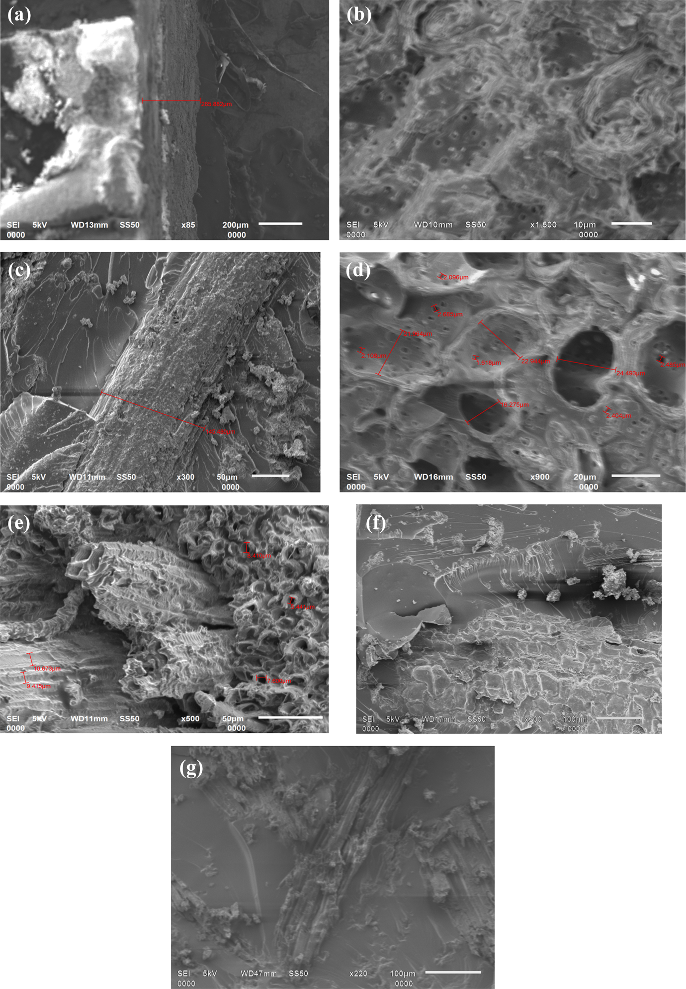
SEM images of fracture surfaces (a) saw cut, crack tip and fracture zone, (b) dispersion of walnut shell particles, (c) adhesion of walnut shell particles on coconut fibre, (d) mode I (TPB geometry), (e) mode II (FPB geometry), (f) mixed mode Me = 0.960 and (g) mixed mode Me = 0.899. SEM: scanning electron microscopic; TPB: three-point bend; FPB: four-point bend.
The fracture processes taking place on or in the vicinity of the fracture surface are analysed using SEM. Figure 8(d) and (e) shows that the fracture surface just near the crack tip of the mode I and mode II specimen failed under the three-point bending and the four-point bending, respectively. It is reported that the pull out of the particle or fibre from the matrix material indicates a bridging mechanism in particle–fibre-reinforced composites. 36 Figure 8(d) reveals that failure occurs due to pull out of the particles and fibres without noticeable plastic deformation. The plastic deformation could not be noticed because of the presence of hard walnut particles in the matrix material. The material is in front of the crack tip in the presence of hard particles of walnut shell, the crack propagates through the matrix material leaving almost negligible plastic deformation. Johnsen et al. 35 in their study have reported that particle de-bonding is one of the major toughening mechanisms for nanoparticle–epoxy composites. Figure 8(e) shows the fracture surface of the FPB specimen failed under pure mode II condition. In Figure 8(e), exposed fibres can be observed in large numbers and length compared to Figure 8(d), where most of the fibres are broken without sliding, which denotes strong interfacial adhesion characteristics. Hence, under mode II loading, the failure of the biocomposite is mostly because of fracture of the fibres. However, very few pull out failures of the fibres and particles are also seen in Figure 8(e). From these observations, it can be said that under pure mode II loading the failure is mainly due to shearing and the growth takes place in a curvature manner. This restricts the de-bonding of the fibre and the crack propagates due to splitting of the fibres into two or more pieces.
Figure 8(f) and (g) shows the SEM micrographs of fracture surface of the biocomposite broken under mixed-mode loading conditions. Figure 8(f) and (g) presents the fracture surface of specimen for α = 15° and 30°, respectively. The random orientation of fibres and breaking of fibre are clearly visible in Figure 8(f). Figure 8(f) reveals hybrid failure mechanism of fibre cracking and fibre pull out. Some parabolic features are also present in Figure 8(f). This type of pattern is seen in mixed mode (α = 15°) along with some matrix cracking and particle pull out. Under mixed-mode loading condition, the crack initiates at an angle θ0, does not grow in a straight line and the crack path profile is curved. The curved path of crack growth can be due to the fact that the MTS direction changes as the crack advances. Thus, at each step of crack propagation, the crack plane rotates and grows in a new direction which has the MTS. The presence of stiff walnut shell particles in each step of crack plane rotation can provide a high resistance against crack propagation, which results in a higher fracture energy. A curved fracture trajectory comes across more particles during its extension resulting in an increased reinforcement efficiency of these particles. One of the most important fracture mechanisms in the particulate composite is crack deflection. 41 Ayatollahi et al. 36,42 have already mentioned that such crack deflection and crack deviation mechanisms resulting to a curvilinear crack path in their studies. In Figure 8(d), it is observed that the initial crack plane and the crack initiation planes are different. This indicates about the increased shear effect under mode II dominant loading. Figure 8(e) and (f) shows that the fracture surfaces are rougher than that of α = 0°. The increasing roughness indicates that the intermolecular forces may be less and because of reinforcing effect the failure load increases. Similar conclusions are made by Wetzel et al. 41 Besides the above observations, some features like the waviness and curved shape of fillers in the matrix are also seen. These natures of the particles make the pull out process more difficult and result in higher fracture resistance.
Conclusions
The use of coconut fibres and walnut shell particles as reinforcing materials in epoxy resin are made and the mode I, mode II and mixed-mode I/II fracture toughness are investigated. Hybridization of fibre with particle improves the fracture toughness of the biocomposite material. The overall mean values of mode I and mode II fracture toughness of biocomposite are 1.279
Footnotes
Declaration of Conflicting Interests
The author(s) declared no potential conflicts of interest with respect to the research, authorship, and/or publication of this article.
Funding
The author(s) received no financial support for the research, authorship, and/or publication of this article.