
Abstract
In this study, the direct melt impregnation of unidirectional glass fiber tapes in an injection molding process is investigated. The simple textile structures were used for a load-adapted reinforcement of injection-molded parts, determining the impregnation quality by mechanical tests. A sandwich layer construction was made with an outer unidirectional fiber layers and an inner injection-molded layer with pure or additionally short fiber-reinforced polypropylene (PP). The glass fiber tapes were produced in a continuously working fiber–foil process where the aligned fiber bundles have been fixed with one side on a PP foil under temporarily acting pressure and temperature. A special bundle spreading device reduced the number of individual fiber layers, which ensured the direct melt impregnation in the injection molding process. The mechanical properties of the sandwich structures were determined using a three-point bending flexural test as well as Charpy and puncture impact tests to investigate the energy absorption. The results were compared to unreinforced and globally short fiber-reinforced test samples. The local reinforcement, designed for bending stiffness and energy absorption, led to a considerable reinforcement effect with minimal mass increase in comparison with the short fiber-reinforced samples. The fiber masses required to achieve commensurable properties were significantly reduced. Thus, when using the fiber tapes, only one-third of the fiber mass necessary for reinforcement with short glass fibers was required.
Keywords
Introduction
Injection molding is one of the most profitable techniques to fabricate thermoplastic components. Classical fiber-reinforced injection-molded parts are mainly produced by injecting a thermoplastic melt that has been previously filled with fibers. Short- and long-fiber granulates with fiber lengths ranging from approximately 0.5 mm to 15 mm are available as raw material. However, as a rule, plastifying and injecting cause fiber length to decrease significantly. In addition, the fibers are aligned irregularly, which negatively impact the mechanical properties. Thus, the mechanical properties of fiber-reinforced injection-molded parts are significantly lower than those of thermoplastic-pressed components with textile reinforcement, which are fabricated by means of semifinished parts for prepregs. 1
Consequently, numerous studies are aimed at enhancing the mechanical performance of fiber-reinforced injection-molded parts. By introducing endless fiber rovings directly into the plastification unit, fiber shortening can be partially avoided. However, the limitation of fiber length to a few millimeters remains basically preserved. 2,3
With the integration of thermoplastic prepregs into the mold cavity during injection molding these weaknesses can be avoided. Adequate manufacturing technologies have already been technically perfected and are able to back-inject the thermoplastic prepregs to shape the stiffening elements or complex geometries. In this process, it is also possible to form the prepreg during closing of the injection mold. 4 To utilize the reinforcement effect, a matrix–matrix bonding of the prepreg matrix with the injection molding plastics is required. Studies show that aside from the application of identical thermoplastics, preheating of polymer surfaces or catalyzing technologies make sense. 5 However, thermoplastic prepregs are expensive because they are subjected to extremely energy-intensive preliminary manufacturing processes, so they have hardly gained general acceptance.
The use of partially impregnated textile structures, whose impregnation will be completed in the injection molding process, is considered particularly advantageous. Apart from lower manufacturing costs, the impregnation process with the injected melt leads to anchoring between the textile structure and thermoplastic melt as observed in in-mold decoration processes. 6 The direct melt impregnation of textile structures, made from glass fibers, has been sufficiently investigated for continuously working melt pool techniques. The experimental fundamentals and calculation approaches were provided by Gaymans and Wevers and Bates and coworkers, 7 –10 in which glass fiber bundles and tapes were drawn over reverse pins in open melt pools and impregnated over a shaped pressure wedge.
In the study by Khondker et al., 11 the bonding of PP knit fabrics by means of injection compression for self-reinforcement was investigated. It was demonstrated that higher temperatures in the molten material and the injection mold result in enhanced adhesion and impregnation, since the molten material takes much time for impregnation. Self-reinforcement by means of knit fabrics made it possible to improve particularly the impact properties, strength values, and elongation at fracture.
It has been shown that, in highly viscous thermoplastic melts, impregnation is only conducted in a pressure-controlled manner, and it is necessary to subdivide into macro- and microimpregnation. The macroimpregnation describes the embedding of the textile structure and fiber bundles (rovings), while the microimpregnation includes the enveloping and wetting of all single fibers within the roving. Flow velocity in the rovings is significantly lower due to less permeability. For this reason, microimpregnation runs more slowly and only under high pressurization than macroimpregnation. As a consequence, this is generally accompanied by a faster flow outside, which in turn results in entrapped air in the rovings. Consequently, impregnation of the textile semifinished parts has to be adjusted to the progress of the flow front inside. 12
In a previous work, we introduced a model that described the impregnation characteristics of unidirectional rovings, given a lengthwise overflow during injection molding and verified the resultant-combined flow and impregnation simulation via simple experiments. 13 It was demonstrated that the impregnation of rovings is carried out in a direction perpendicular to lengthwise flow and that an impregnation gradient appeared due to pressure built up along the path of flow. The presence of entrapped air and variations in flow velocity between macro- and microimpregnation were also found.
In the study by Tröltzsch and Kroll, 14 the maximum number of filament layers lying atop on another that can be impregnated in the injection molding process was clarified. Thereby, it was possible to conclude the number of impregnated filament layers based on a modified fiber bundle pullout test. The number of filament layers to be impregnated determined in the tests, which amounts to approximately 10 filaments lying atop, resulted in a minimum distribution of the rovings necessary to impregnate all filament layers and to avoid entrapped air inside the roving. Lower roving densities of maximum 1200 tex proved ideal, which, in turn, have a minimum distribution of 3.5 mm. Based on this result, we used for the production of the fiber tapes the 1200-tex roving, which proved to be suitable for the investigation in this study.
Experimental setup
Manufacturing of fiber tapes
The unidirectional glass fiber tapes were produced in a continuously working calendar, illustrated in Figure 1. For this, eight glass fiber rovings of 1200 tex each (EC 17-1200-E35, produced by PD Glasseide Oschatz, Germany) were used. These rovings were characterized by a silane sizing for thermoplastic matrices with a loss on ignition measured as 0.7% (DIN EN ISO 1887). The glass fiber rovings were aligned in parallel on a spool. After removing them from the spool rack, the rovings passed a unit consisting of guide rollers of convex shape, which caused a spreading of the filaments and minimized the superposed individual fiber layers. On average, it was possible to achieve a spreading of the rovings up to 10 mm. As a result, the total width of the resultant fiber tape was about 70 mm. Due to the fiber spreading, the number of superposed individual filaments was diminished to 5 on average. After the formation of the fiber pattern, a 100-µm thick PP foil was applied to one side of the fiber tape for fixation. The foil was made of a PP homopolymer with 2 wt% polypropylene-grafted maleic anhydride (PP-g-MAH). To protect the filaments in the lamination process and avoid adhesion to the calendar rolls, silicone paper was applied as a separating layer on both sides. In the next step, PP foil and glass fiber were heated in a temperature-controlled field of radiant heaters to approximately 180°C. Subsequently, the PP foil was pressed with the glass filaments in the calendaring process. The flow-through speed was about 1 m/min. The material was subjected to pressure and temperature for a short time, bonding the outer filament layers to the thermoplastic foil and fixing the rovings in a unidirectional manner. Spreading out the eight 1200-tex rovings to a width of 70 mm and using the 100 μm thick PP foil, a basis weight of approximately 220 g/m2 was achieved with a fiber volumetric content of approximately 40%. Total tape thickness amounted to approximately 0.15 mm (Figure 1).
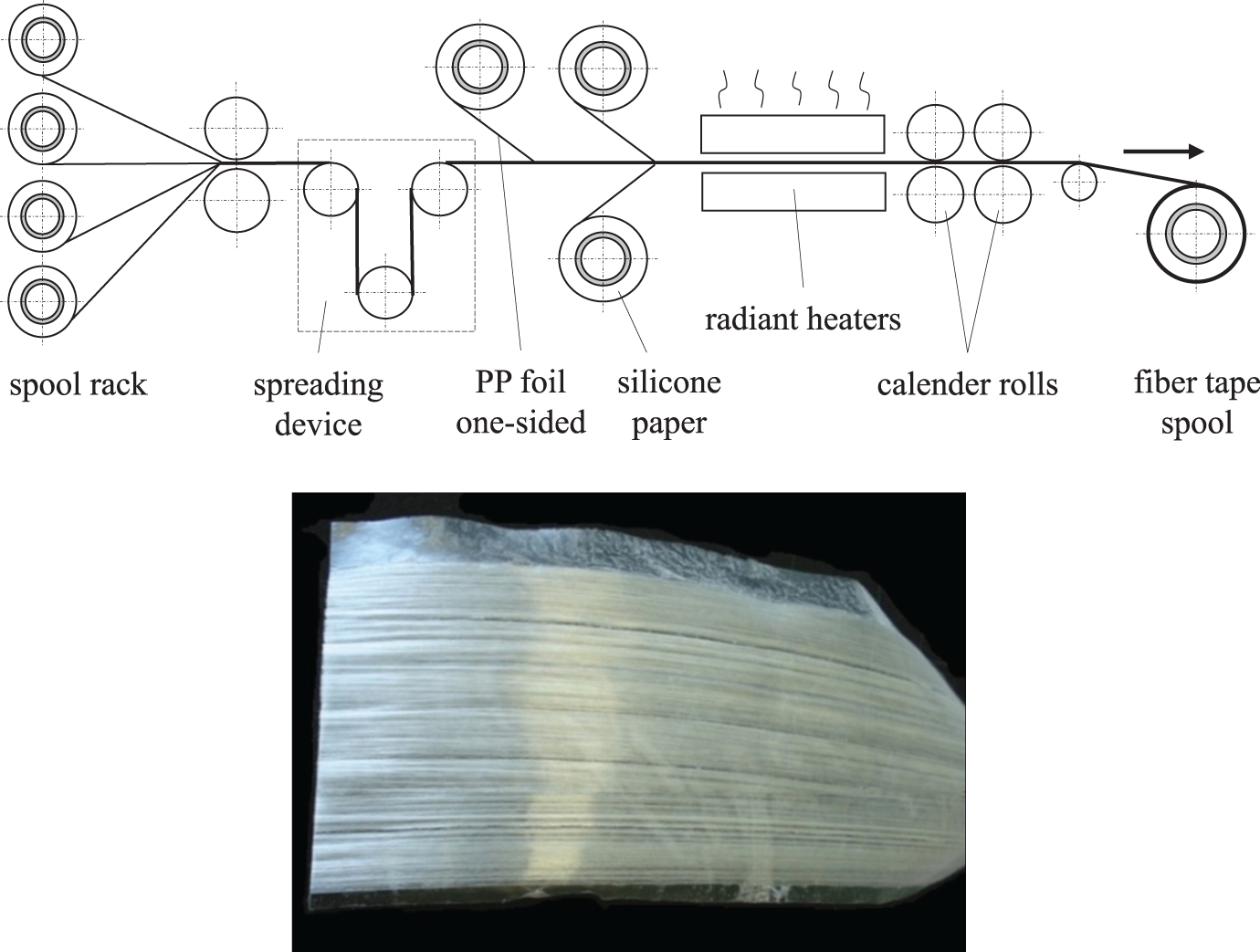
Scheme of the fiber–foil calendar unit (above) and manufactured fiber tape (below).
Injection molding
For the injection molding tests, a mold with a plate-like cavity of 250 × 100 × 3.5 mm3 was used. In the cavity, two sections of the previously produced fiber–foil tapes were aligned so that the side laminated with foil adhered to the mold walls. Subsequently, the plastic material was injected between the two fiber tapes via a hot runner sprue from the parting line (Figure 2). With the melt flow over the tapes, the fibers were impregnated. At the same time, the melt pressure caused the tapes to be pressed against the cavity walls, thus resulting in a good fixation during the filling process and avoiding a reorienting of the glass filaments.
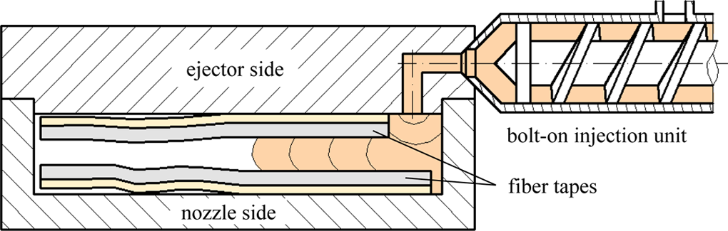
Scheme of the injection-molding process with integrated fiber tapes.
The mold was equipped with dynamic resistance heating just behind the cavity walls, thus making it possible to preheat the integrated fiber tapes. Preheating of the tapes began with shutting the mold. The ceramic heating was heated up to 150°C within 15 s and kept this temperature constant for about 20 s. In the injection molding cycle, injection was delayed by 30 s, so that the fiber tapes could be preheated in the cavity. After this delay, filling of the mold cavity began. Shortly after starting the injection, dynamical tempering switches over to cooling, so that the cavity walls were cooled down to the demolding temperature of 45°C within the packing phase. The cycle time in whole lasted about 90 s.
The PP homopolymer Moplen HP 500V (LyondellBasell, Houston, Texas, USA) was used for the injection molding tests. The high-fluidity polymer was measured with a melt flow rate of 120 g/10 min (ISO 1133; 230°C/2.16 kg). This PP was also compounded with an additional glass fiber content of 20 wt% and 40 wt% and 2% PP-g-MAH as compatibilizer to achieve a better fiber–matrix adhesion. The melt flow rate was then decreased to 69 g/10 min for a content of 20 wt% and 50 g/10 min for a content of 40 wt%. Table 1 compares the mechanical properties of the three variants of PP used, with varying fiber contents. The properties were determined using injection mold tensile specimens according to DIN EN ISO 294-1, shape type A.
Mechanical properties of the PP types used for the injection-molding tests.
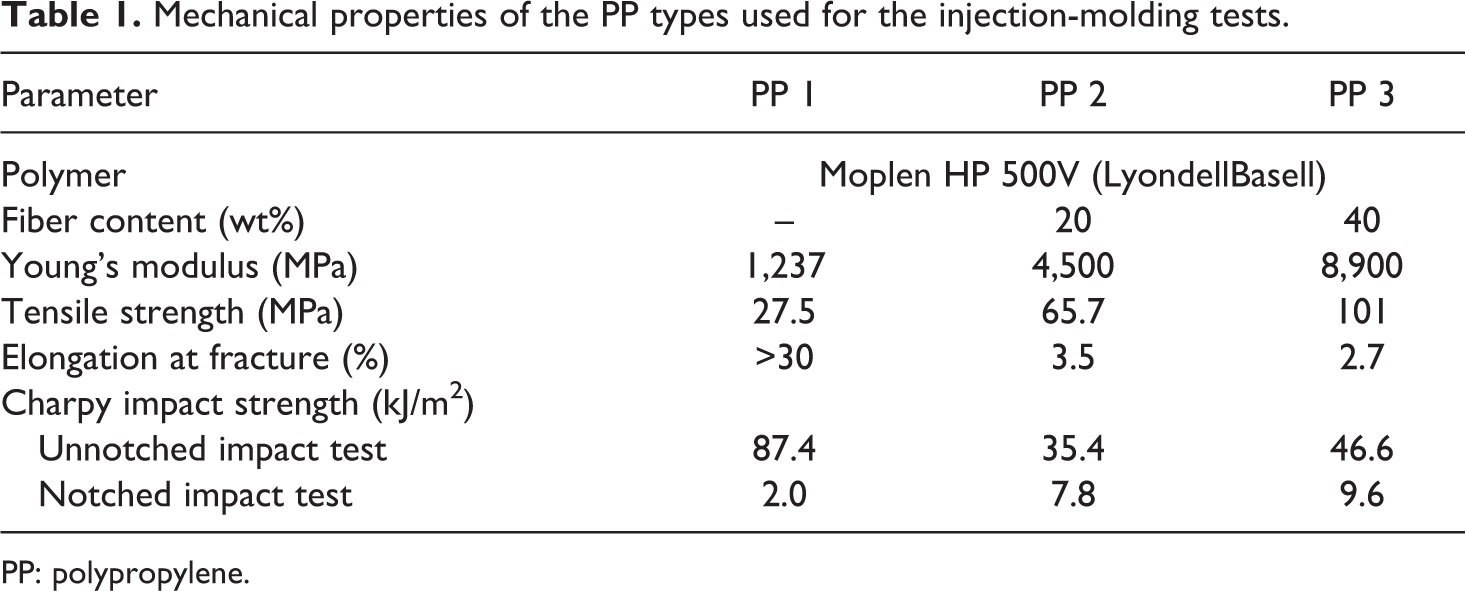
PP: polypropylene.
Mechanical and optical tests
For testing the molded fiber tape sandwiches, standard specimens were cutoff the 3.5 mm thick sandwiches using a water jet cutter. The three-point bending flexural test according to DIN EN ISO 178 standard was conducted to determine bending stiffness. For this test, a tensile testing machine of the type Inspekt 1464 (Zwick/Roell, Germany) with a 2-kN load cell was used. The test was carried out by means of specimens of 80 × 10 × 3.5 mm3 at a span of 72 mm. Test speed amounted to 2 mm/min. The puncture impact test according to DIN EN ISO 6603 was performed with sandwich plates of 100 × 100 × 3.5 mm3. The mandrel-like impact body had a diameter of 20 mm and an impact speed of 4.4 m/s. Acceleration sensors were used to record the load–deformation curve. From this curve, the puncturing energy resulting from the surface below the curve up to a deformation occurring at a force drop of 50 wt% was found. Additionally, the maximum occurring force was determined. The Charpy impact test according to DIN EN ISO 179 was conducted with unnotched specimens and impact of the faces of the blank. The impact was directed perpendicularly to the continuous filament reinforcement and the component wall, thus corresponding to the load direction in the puncture impact test. The test sample sizes were 80 × 10 × 3.5 mm3, the span amounted to 62 mm.
For a qualitative verification of the thermoplastic impregnation of the glass filaments in the fiber tapes, polished micrograph sections of the sandwich plates of all test series were fabricated and inspected with a light microscope. The section plane was thus placed perpendicular to the fiber tapes’ filament orientation (viewing direction corresponds to the flow direction of the injected PP).
Results and discussion
The placement of the fiber tapes in the outer layers of the sandwich plates made by injection molding results most notably in enhanced bending properties. In the three-point bending flexural tests, all test series provided at the beginning the typical linear–elastic material behavior (Figure 3). For the test samples without fiber tapes, this state moved into elastic–plastic characteristics without any transition, with the final failure occurring after application of the maximum force. In the samples with fiber tape reinforcement, after the clearly more rapid linear increase in force, a sudden drop is observed due to the occurrence of delaminations or fiber breakages. Later on, increases in force above the first local stress maximum before the test sample finally broke down could be partially observed.
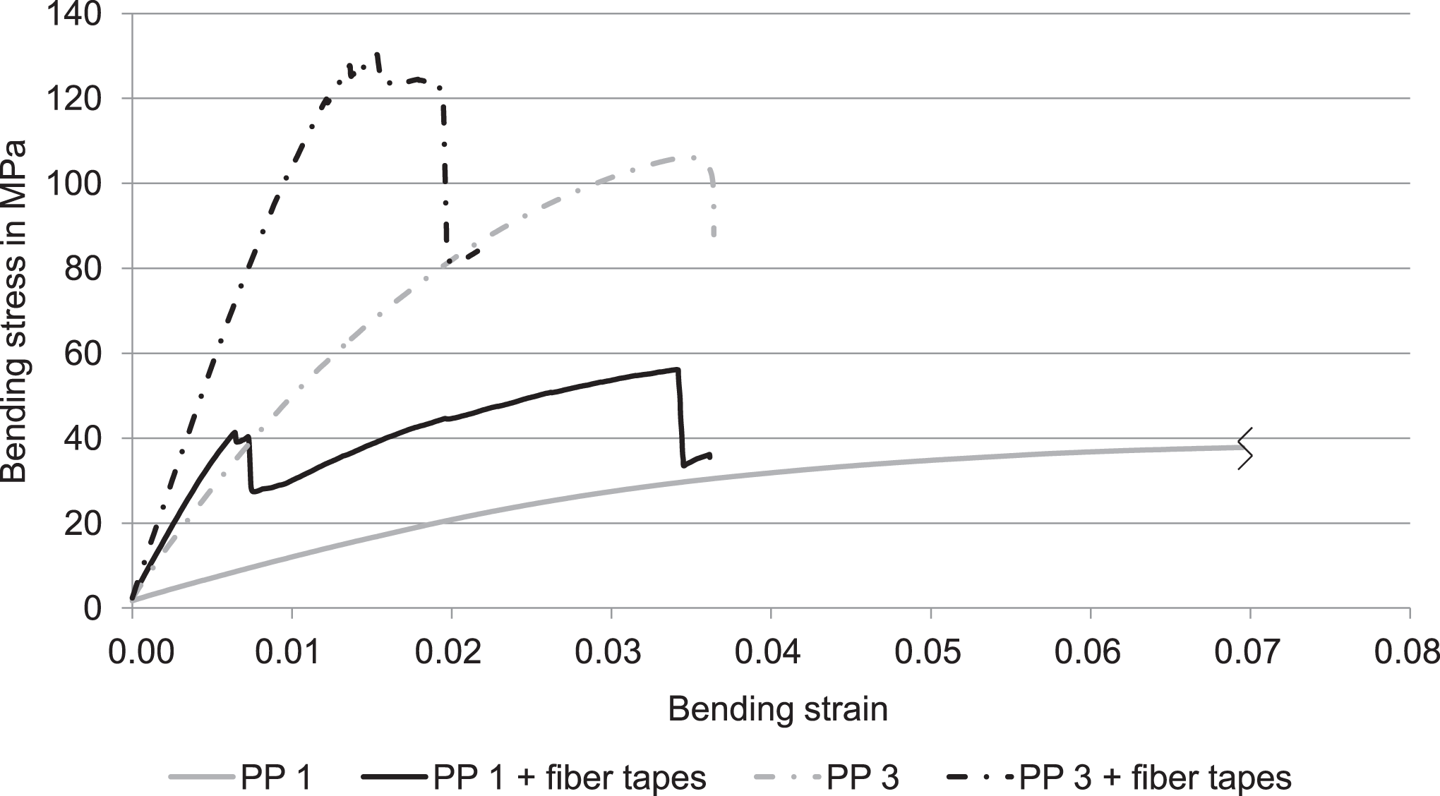
Typical stress–strain curves in a three-point bending flexural test.
A very strong increase in the flexural modulus of the samples with reinforced top layers was verified (Figure 4). In the box plots, the box represents the 25th and 75th percentiles, while the whiskers represent the 5th and 95th percentiles. In this test, we recorded the stiffness of the whole composite to make the test series directly comparable. For this reason, for the fiber tape sandwiches, the flexural modulus represents a kind of mixed modulus covering the total thickness of all layers, without taking into account the individual layers’ stiffness values. For PP 1, stiffness increased by 290%, in case of the short fiber-reinforced materials, PP 2 stiffness increased by 240% and for PP 3 by 71%. Higher viscosity of the short fiber-reinforced PP matrix does not affect the microimpregnation of the filaments during the injection molding process; an increase in stiffness due to bonding of the top layers can be clearly seen. However, with an increase in the content of short fibers in the injected PP core of the sandwich composites, the top layers contributed to greater stiffness to a lesser extent. Here, assuming approximately the same fiber content of the injection-molded core and top layers, the increase in stiffness only results from the unidirectional fiber alignment and fiber length of the fiber tapes. As can be seen, the same bending stiffness values are achieved with the fiber tape sandwiches, using the unreinforced PP 1, as for the plastic panel with PP 3 without fiber tapes. However, in the local reinforcement of the top layers, the fiber content, related to the whole component, is only about 7 wt%. A higher spread of the measured values for the fiber tape sandwiches can be seen. It results from preparation irregularities in the textile structure and in the embedding process of the tapes.
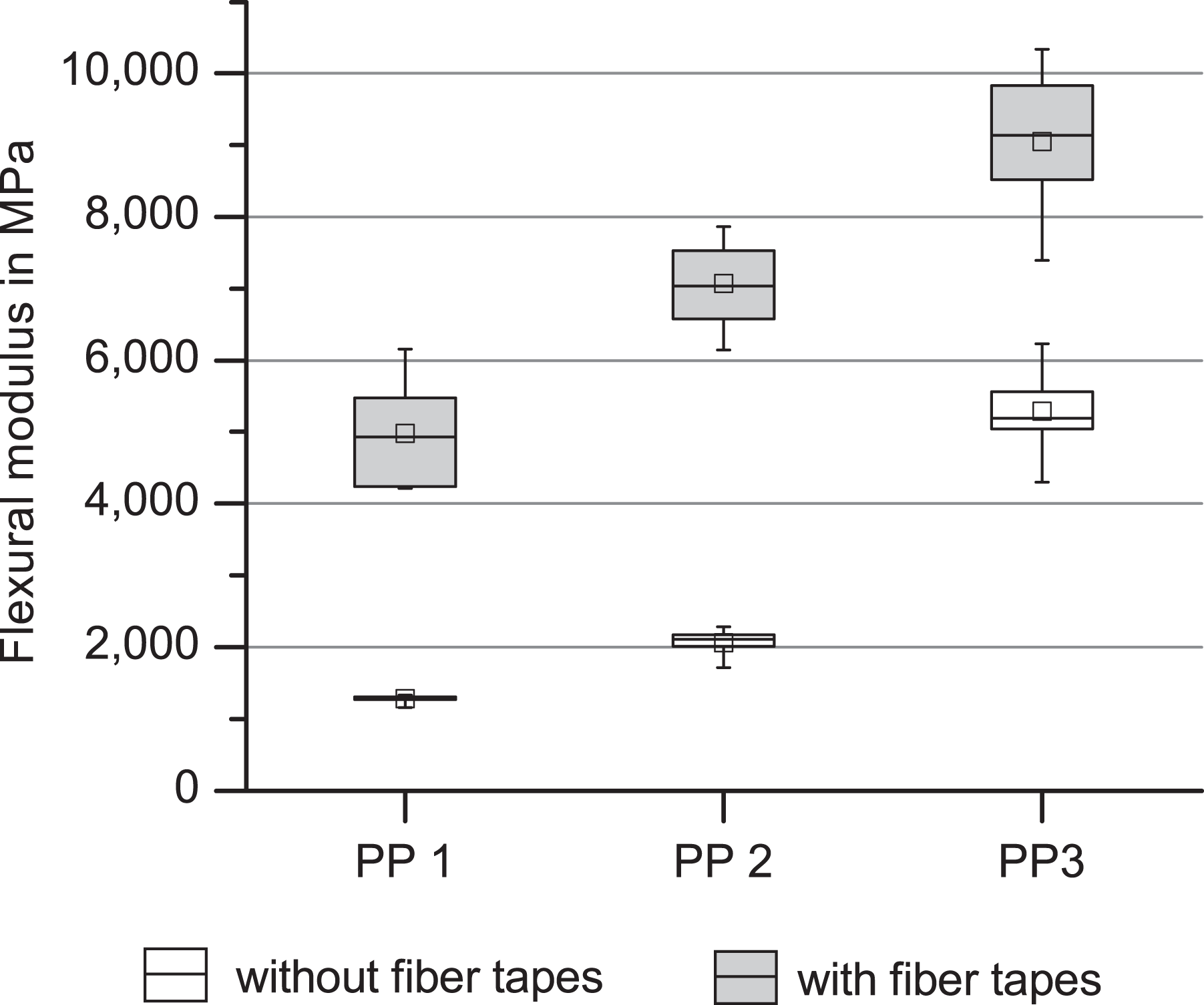
Flexural modulus with and without fiber tapes.
To determine the puncture energies in the puncture impact test according to DIN EN ISO 6603 standard, the force–deflection curve during the puncturing of the test sandwiches was measured. Figure 5 shows typical curves determined for all PP types with different fiber contents, with/without integrated fiber tapes. In the case of the test samples with fiber tapes, it was possible to observe a higher force maximum versus the value of the plastic panels, which is, in most cases, only established at significantly higher deformation. At first, all curves are characterized by a nearly linear progression due to the elastic characteristics during initial deflection. With increasing deformation, the first failure of the plates occurred as a result of the formation of cracks, fiber breakage, and delaminations, linked to a sudden drop of force. The two peaks occurring thereby, which may be identified both for unfilled PP and additional short fiber-filled PP, are typical for plates without top layers. For the test samples with fiber tapes as top layers, no homogeneous curve could be detected. Here, the top layers initially contributed to strong energy consumption. The impact body broke through, since matrices and fibers broke and fibers delaminated at the same time.
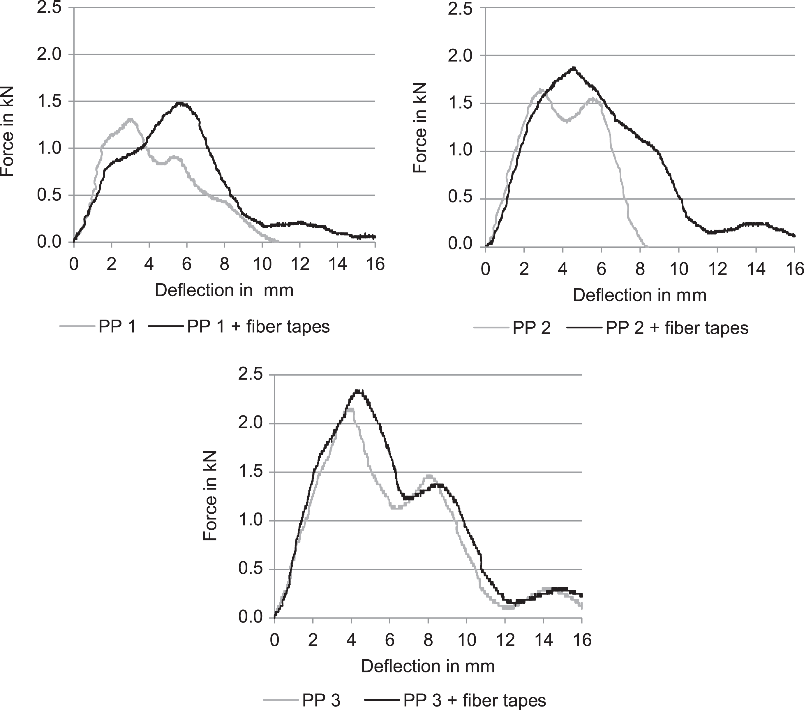
Typical force–deflection curves for the different PP types in the puncture impact test. PP: polypropylene.
Figure 6 outlines the measured force maxima, energy applied up to the force maximum, and the puncturing energy. Ten individual samples of each test series were tested. By means of textile reinforcement, in general, it was possible to determine an increase in the absorbed puncturing energy of 20–35%. In terms of the PP with additional short fiber reinforcement, the increase in puncturing energy was higher than for the test plates with the unfilled PP 1. This may be caused by a better bonding of the fiber tapes submerged and impregnated during the injection molding process, since it was necessary to process the composite with the short fibers at a slightly higher melting temperature of 230°C versus 210°C for the unfilled PP 1. While the force maximum increased continuously over all the test series, for the puncturing energy, we observed a stepwise growth depending on the matrix type. The measured puncturing energy of the sample plates of the unfilled PP 1 with fiber tapes conforms to the puncturing energy achieved for PP 2 without fiber tapes. The same is also valid for the next stage – PP 2 with fiber tapes and PP 3. In relation to the entire mass of the sample plates, the fiber content of the respective two-bonded fiber–foil tapes is only about 6 wt%. Consequently, in direct comparison to the short glass fibers, the continuous filament results in a clearly higher energy absorption or leads to a savings in weight due to the lower fiber content. For the energy applied up to the force maximum, a growth is slightly marked, especially with regard to the spread of the measured values. This indicates that the increase of the energy absorption in the textile-reinforced samples arises mainly from the fiber breakage, fiber delamination, and fiber pullout in the phase of failure.
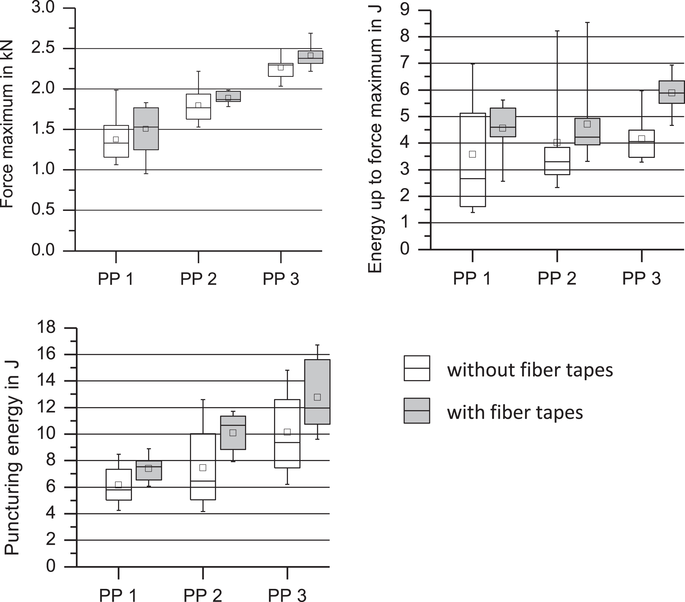
Force maximum, energy up to force maximum, and puncturing energy in the puncture impact test.
The sample plates without textile reinforcement broke down by brittle chipping of a circle-like zone around the puncturing body, accompanied to a great extent by the formation of fragments (Figure 7, left). Depending on crack initiation and crack propagation, huge variations in terms of the achieved energy up to force maximum and puncturing energy appeared. For the samples with fiber tapes, the variations of the individual values, in turn, resulted from inhomogeneities in fiber distribution, which could be found in the fiber–foil tapes. In most cases, cracks propagated in parallel to the fibers within the plastic material. However, the plastic fragments were not broken completely. Due to the armoring effect of the continuous filament reinforcement, only a tearing of the plastic material in the zone of the impact body was detected. Fragments did not splinter off (Figure 7, right).
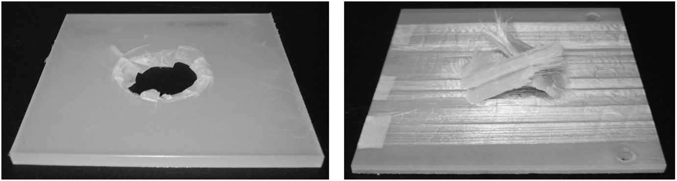
Representative fracture aspects of the impacted specimens.
In addition to the puncture impact tests, Charpy impact investigations were also carried out. The impact direction perpendicular to the fiber tapes’ top layers conforms to the load direction in the puncture impact test. Analogous to the results of the puncture impact tests, a general increase in impact strength for samples with the fiber tapes was found. Thus, a doubling or even tripling of the impact strength values (Figure 8) was observed. As a function of increasing short glass fiber content of the polymer, as expected, impact strength decreased, which in turn led to embrittlement of the entirely plastic material. However, it was possible to compensate for this embrittlement through the additional reinforcement using the fiber tapes.
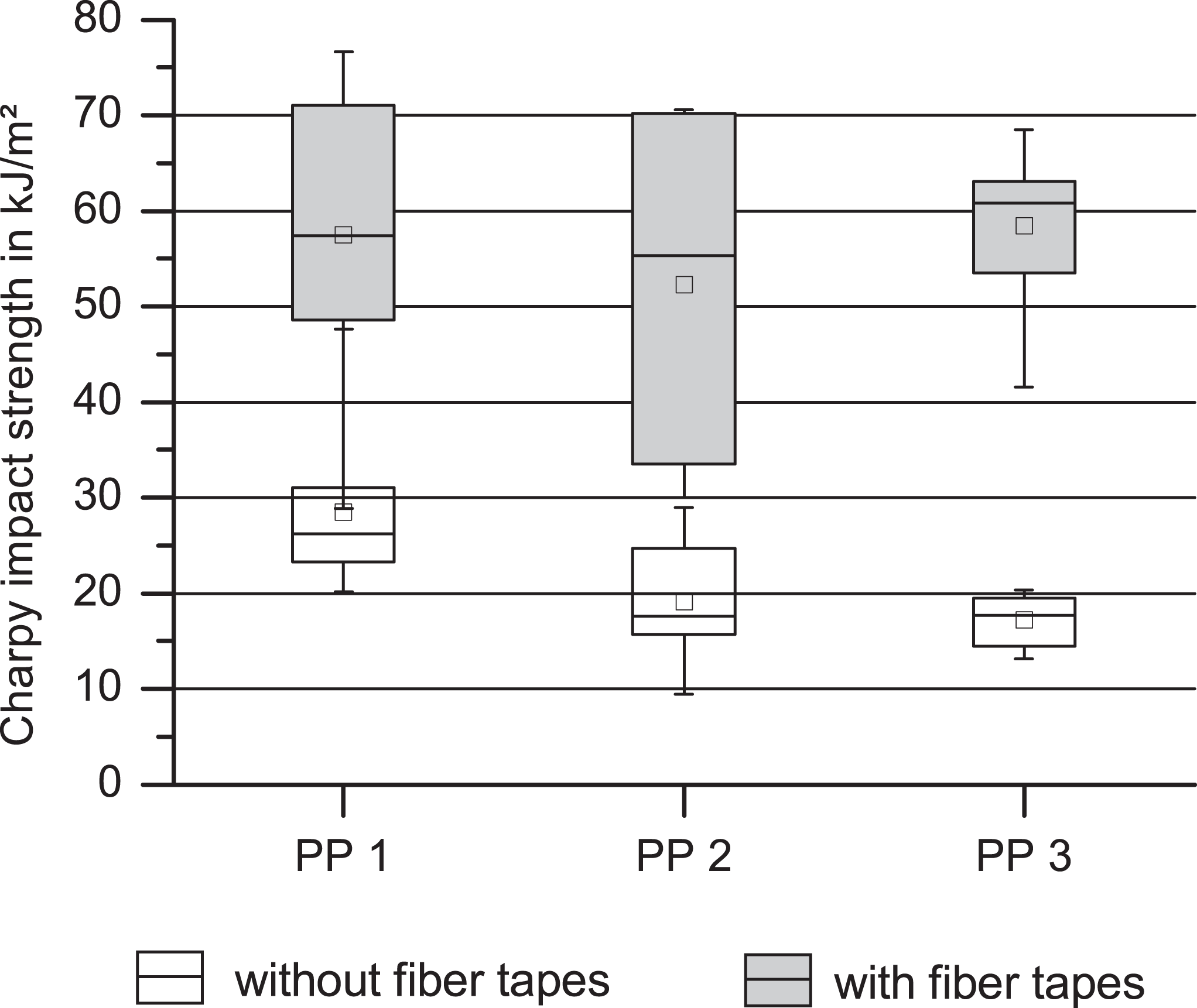
Charpy impact strength.
For a qualitative verification of the thermoplastic impregnation of the glass filaments inside the fiber tapes, polished sections were produced from all cross-sections of the plates and investigated using light microscopy. To do this, the section plane was placed perpendicular to the fiber orientation of the fiber tapes (viewing direction corresponds to the flow direction of the injected polymer melt). In Figure 9, a total cross section of the plates is shown for PP 1 (above) and PP 3 (below), wherein, at the left and right margins of the images, one may observe the cold bonding agent of the polished sample. The fiber layer construction of the sandwich structure can be clearly seen. In general, the fibers were well impregnated with the injected melt. No transition can be found between the laminated PP foil at the surface and the injected thermoplastic material. In conclusion, we may assume that both plastic regions are very firmly bonded and that the fibers have been completely impregnated. In the additionally short fiber-reinforced plates with PP 3 (Figure 9, below), the different fiber layers of the tapes and short fibers oriented due to flow can be clearly observed. In the flow center, we observed typical fiber orientation mainly perpendicular to the flow direction, whereas in the outer regions, due to high flow rate gradients, a fiber orientation in the flow direction can be identified. A noteworthy phenomenon is the depletion of fibers in the marginal region of the fiber tape at the left side. This one-sided depletion of fibers results from the sprue, which is placed asymmetrically; this sprue requires that the flow of the molten material be turned after its entry into cavity (see Figure 2). In the shadow of the flow, in turn, we find this depletion of fibers.
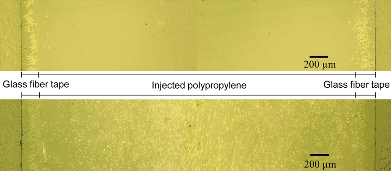
Polished micrograph sections of the fiber tape sandwich with PP 1 (above) and PP 3 (below), magnification: 100×. PP: polypropylene.
The foil lamination in the calendar process not only lead to a fixation of the fibers but also served to prevent them from refloating to the part surface. Figure 10 shows polished sections of the sandwich plates in the region of the bonded fiber tapes in 500× magnification for the PP 1 and the PP 3. Even with this enlargement, no boundary layer between the foil and the injected PP can be detected. In the polished section of the PP with the short fiber filler, breakouts can be observed at the fiber margins, which imply weaker fiber–matrix adhesion. Since the PP 3 to which short glass fibers were added has a lower capacity to store thermal energy than the unfilled PP 1, it cools down more quickly at the surface and thus has less reaction energy to adhere to the glass fibers of the submerged fiber tapes. In sum, no noteworthy decrease in the impregnation level due to cooling down could be found along the flow path length of the molten material. Only in the marginal regions of the cavity, in which the resistance heating no longer had any effect or which already had a temperature gradient, both larger regions which remained unimpregnated and a weaker adherence of the entire fiber–foil tape to the injection-molding plastic material could be detected.
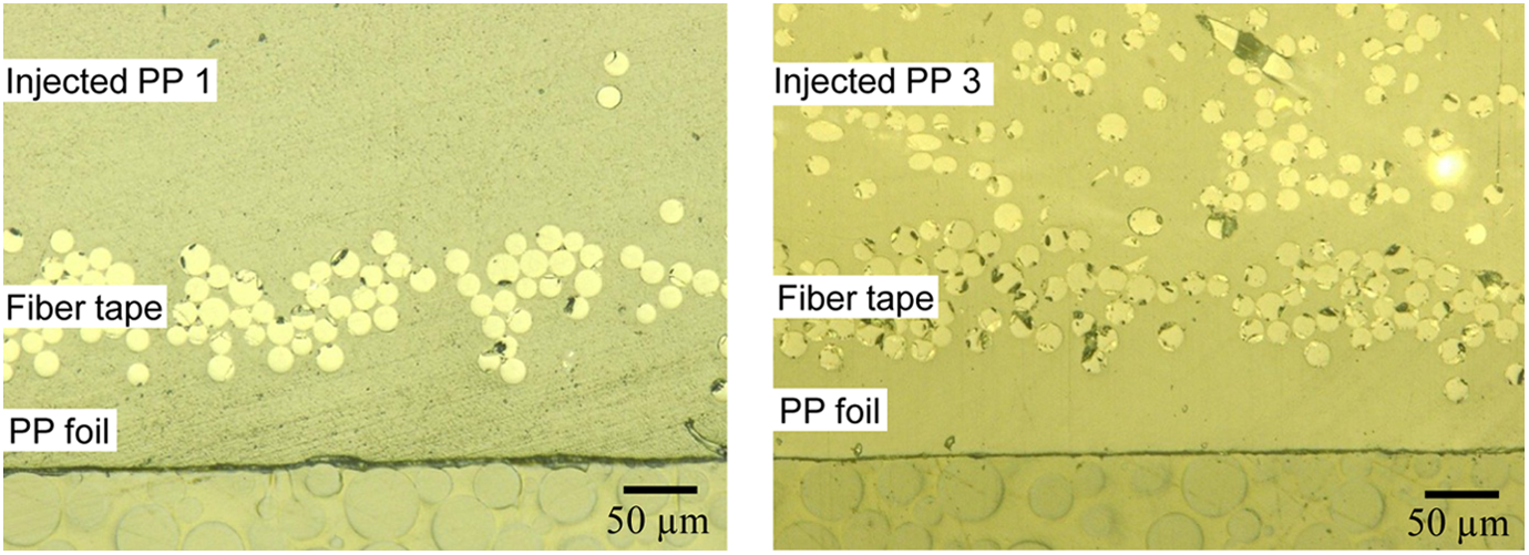
Polished micrograph sections of the fiber tape sandwich with PP 1 (left) and PP 3 (right), magnification: 500×. PP: polypropylene.
Conclusion
Plastic components can be locally reinforced in a load-appropriate manner by integrating textile reinforcement structures into injection molds. As a rule, for this reinforcement, previously impregnated, costly textile semifinished parts (thermoplastic prepregs) have already been used. This article sought to determine whether it is possible to use simple textile structures that are directly impregnated in the injection molding procedure for reinforcement purposes and how great an increase in mechanical performance may be expected.
In preliminary studies, the authors succeeded in clarifying fundamental aspects of flow dynamics and impregnation characteristics by describing the bonding of fiber rovings in the injection molding procedure. Based on these fundamentals, in the experiments carried out within this article, unidirectional glass fiber tapes were laminated on one side with a fixing foil in a fiber laminating device and then processed into plate-like sandwich structures through injection molding. The distribution of the fiber rovings achieved in the textile fabrication process permits a significant decrease in the content of superimposed filament layers, which, in turn, provides for thorough fiber impregnation in the injection-molding procedure. For impregnation, we applied a slightly viscous PP, either unfilled or filled with short glass fibers. Although the viscosity of the molten material was increased thereby, it was possible to thoroughly impregnate the fiber tapes.
The sandwich plates produced were characterized by significantly enhanced mechanical properties. Primarily bending stiffness and impact strength were increased due to the fiber tapes as top layers, which were integrated in a way customized to accommodate stress. In comparison with the fabricated reference plates with global reinforcement using short glass fibers, the fiber masses required to achieve commensurable properties were significantly reduced. Thus, when using the fiber tapes, only one-third of the fiber mass necessary for reinforcement with short glass fibers was required. Combining local reinforcement with continuous filaments tailored to stress and global reinforcement with short glass fibers makes it possible to dramatically increase both strength and stiffness and, simultaneously, to maintain impact strength at a high level. Thus, it is possible to compensate for embrittlement, which arises due to the highly filled thermoplastics and lower impact strength – both phenomena result from reinforcement by continuous filaments.
Footnotes
Declaration of Conflicting Interests
The author(s) declared no potential conflicts of interest with respect to the research, authorship, and/or publication of this article.
Funding
The author(s) disclosed receipt of the following financial support for the research, authorship, and/or publication of this article: This work was supported by the German Federal Ministry of Education and Research (BMBF) [grant no. 03IPT508X] and the German Research Foundation (DFG) [grant no. EXC 1075]. Financial support is gratefully acknowledged.