
Abstract
Filler treatment is one of the recognized methods that can be implemented to improve the mechanical properties of composite materials. However, no research has examined this particular issue from the dynamic perspective. Hence in this study, both untreated and treated polypropylene (PP)/muscovite (M)-layered silicate composites were tested under static and dynamic loadings of up to 1100 s−1, using a universal testing machine and split Hopkinson pressure bar apparatus, respectively. M particles were treated with lithium nitrate and cetyltrimethylammonium bromide as a surfactant, through an ion exchange treatment. This treatment process was successfully proven, using Fourier transform infrared, X-ray diffraction, and transmission electron microscopy analyses. Results show that the treated PP/M specimens with a fine state of dispersion level show better mechanical performances under a wide range of strain rates that were investigated, when compared with the untreated PP/M specimens. In addition, the mechanical properties of both the tested PP/M-layered silicate composites also show great dependency on the strain rate applied, where yield stress, compression modulus, ultimate compressive strength, and absorbed energy steadily increased when the strain rate was increased. However, the yield strain shows a contrary trend. Postdamage analyses were found to be consistent with the mechanical results for both tested specimens.
Keywords
Introduction
Layered silicates have been widely used as reinforcement materials or fillers in polymer composites due to their abundance, high strength, large interface, and ability to achieve considerable reinforcement at a very small filler loading. Compared with conventional fillers, they exhibit very high aspect ratios and very thin layer thicknesses of around 1 nm. Stacking of the layers leads to a regular van der Waals gap between layers, commonly called the gallery or interlayer. 1 Having the ability to be dispersed individually and also an excellent surface chemistry, they have attracted a large amount of attention from both science and industry. Nevertheless, several crucial factors should be taken into consideration during the fabrication of the polymer-layered silicate composite, especially on the phase compatibility between the layered silicate filler and the polymer matrix. 2 Among many different types of layered silicates, muscovite (M) has become a more promising reinforcement than other conventional layered silicates with a similar nature. This is due to its well-defined crystal structure, molecularly smooth surface, outstanding corona resistance, high aspect ratio, and availability in large amounts at relatively low cost. 3 In addition, the aspect ratio of M is higher than that of montmorillonite. The chemical formula of M is KSi3Al3O10·(OH)2 and has a very high layer charge density close to 1.0 equivalent per O10(OH)2. M belongs to a monoclinic structure with a space group C2/c and with cell parameters a = 5.18 Å, b = 8.99 Å, c = 20.07Å, and β = 95.751. 4
For M-layered silicate composites, there are several factors that need to be carefully considered, especially compatibility issues between the particles and the matrix. Pavlidou and Papaspyrides speculated that M particles may face obscurity to homogeneously disperse within a polymer matrix, due to their preferred face-to-face stacking in agglomerated tactoids as well as the incompatibility issue between the hydrophilic nature of layered silicates with the hydrophobic polymer. 2 Therefore, active debates on the modification method have been carried out by previous researchers, in order to overcome these dilemmas. 5 –7 For example, Shimizu et al. 5 and Kodama et al. 6 deployed alkaline earth metal and transition metal ions as their exchange cations. Meanwhile, Bracke et al. and Meier et al. used lithium (Li) as their exchange cations for biotite M and phlogopite. 7,8 Unfortunately, the implemented exchange cations did not significantly enlarge the basal spacing of M particles through the ion exchange treatment. Based on these findings, in this study we have demonstrated a two-step ion exchange treatment, in order to further enlarge the basal spacing of M particles. In the first step, the M particles were treated using lithium nitrate (LiNO3), followed by quaternary alkylammonium cation.
From a characterization point of view, most of the previous studies only focused on the statistically determined mechanical properties of M-layered silicate composites. 3,9,10 Unfortunately, no research has been reported on the effect of filler treatment on the dynamic mechanical properties of M-layered silicate composites. Hence, the knowledge is still unclear and consequently additional attention is required. Based on this concern, the experiment reported here was purposely designed to counteract the lack of information in this specific area. To achieve our goal, M particles were treated using a two-step ion exchange treatment. The effectiveness of the ion exchange treatment was characterized using Fourier transform infrared (FTIR) spectroscopy, X-ray diffraction (XRD), and transmission electron microscopy (TEM). For mechanical analysis, an experimental technique based on the compression split-Hopkinson pressure bar (SHPB) was introduced to perform high strain rate testing, whereas a conventional universal testing machine was used to perform static compression testing on both untreated and treated polypropylene (PP)/M-layered silicate composites. For comparison purposes, the responses of both the untreated and treated PP/M-layered silicate composites were characterized in terms of their stress/strain curves, yield strength, ultimate strength, and stiffness. Furthermore, a correlation between the applied strain rate and filler loading, using rate sensitivity, thermal activation volume, and absorbed energy, up to a certain deformation (0.025 of strain), was carried out. Postdamage analysis was also performed to further identify the failure mechanism experienced by the specimens under dynamic loading up to 900 s−1.
Experimental details
Materials
A PP homopolymer (Titanpro® PM-255), with a melt flow index of 1.6 g/10 min at 230°C and a polymer density of 0.91 g/cm 3 , was purchased from Titan PP Polymers (M) Sdn Bhd (Malaysia). M particles were obtained from Bidor Mineral (M) Sdn Bhd (Malaysia) with a cation-exchange capacity (CEC) of 82 meq/100 g. Organically modified M was prepared by cation exchange of LiNO3 and cetyl trimethylammonium bromide (CTAB), supplied by Sigma Aldrich (M) Sdn. Bhd (Malaysia), according to the method proposed by Yu et al. 11
Ion exchange treatment of M particles
In this study, M particles were treated using a two-step ion exchange treatment and details of the treatment are described subsequently.
LiNO3 treatment of M particles
A mixture of 10 g of M powder and 170 g of LiNO3 powder was mechanically mixed and then heated in a furnace at 300°C for 12 h. The resulting product was washed seven times and filtered with deionized water. Subsequently, the product was dried at 110°C using a vacuum oven. The end product was named Li-M.
The intercalation of Li-M with CTAB
The preparation of Li-M with CTAB was undertaken under hydrothermal conditions. An ion exchange treatment was obtained using different levels of modification, with CEC CTAB/M ratios of 1 (82 meq/100 g), 1.2 (92 meq/100 g), and 1.6 (132 meq/100 g). First, CTAB was dissolved in deionized water and then Li-M was mixed with the CTAB aqueous solution at room temperature. Next, 100 ml sample of the mixture was placed in a hydrothermal reactor with a Teflon®-lined stainless steel autoclave and heated at 200°C for 12 h. After the reactions, all surfactant-M products were filtered, washed three times with ethanol, dried in a vacuum oven at room temperature, ground in an agate mortar, and finally stored in a desiccator. The obtained CTA+ M samples were named organomuscovite (OM).
Sample preparation
During the first stage of sample preparation, M and OM particles were dried at 80°C in a vacuum oven for 24 h, in order to remove excess moisture. The M and OM particles and PP were then mixed and compounded for a period of approximately 8 min, using a Thermo Haake Polydrive R600 (Thermo Electron, Karlsrule, Germany) internal mixer at a mixing temperature of 180°C and a rotor speed of 50 r min−1. The processing conditions involved melting the PP in the preheated mixing chamber of the internal mixer for 4 min. Well-dried M and OM particles were then added gradually at 30 s intervals, and the mixing process was continued for 8 min. After that time had elapsed, the compounded specimen was discharged from the mixing instrument and immediately sheeted through a laboratory mill at a 1 mm nip setting. This was for the purpose of specimen handling during the hot press process. The compounded composite sheets were then cut into small pieces before being hot pressed. For standardization, 5% by weight of both untreated M and OM were concisely added into the PP matrix for each type of PP/M-layered silicate composite.
Characterization of ion exchange treatment
FTIR spectroscopy
FTIR analysis was carried out to understand the effectiveness of the ion exchange treatment on the M particles. In this study, FTIR analysis was performed using a Perkin-Elmer® Spectrum One spectrometer (Waltham, Massachusetts, USA) and the attenuated total reflection technique was adopted. M particles were mixed with dried powdery potassium bromide and ground using an agate mortar and pestle to obtain fine particles. The mixture was pelletized using a Specac 1 hydraulic press (UK) at 8 ton pressure and then was scanned 32 times. The scanning using the FTIR spectrometer was carried out in the range of wavelengths from 4000 cm−1 to 400 cm−1 with 4 cm−1 resolution.
X-Ray diffraction
XRD is an important analytical tool to investigate the crystal structure of solids. In addition, this technique can be manipulated to determine the intercalated structures of ordered crystalline materials, especially clay. When organic species such as surfactants or polymers are introduced into the galleries, the adjacent clay platelets will move away from each other along the c-axis. This shift will be recorded by XRD analysis. The 001 Bragg peak shifts to the left in the XRD spectrum are according to the Bragg’s formula in equation (1):

Transmission electron microscopy
TEM analysis is an important visual technique that has been used to characterize layered silicate nanocomposites. It portrays clay morphology at the nanometer level. If TEM results are combined with the XRD results, an accurate structure of the nanocomposite can be elucidated. The morphology analysis was carried out with a Libra® 120 TEM (Zeiss, Germany), applying an acceleration voltage at 120 kV. A Power Tome PC microtome was used to prepare the specimens. Ultrathin sections of about 90 nm thickness were cut with an Ultra 450 diamond knife (DiATOME, Hatfield, Pennsylvania, USA) at room temperature.
Postdamage analysis
Field-emission scanning electron microscopy
Postdamage analysis of both untreated and treated PP/M-layered silicate composites was performed using a Zeiss Supra 35 VP FESEM (Germany). The specimens were prepared from cross-sections of the fracture surface. The test specimens were attached to an aluminum mount with a carbon double-side and a sputter with a platinium layer, using a Polaron SC 515 sputter coaterto (Quorum Technologies, Laughton, East Sussex, London) eliminate the electron charging effect.
Mechanical tests
Static tests
The frictional effect is an essential factor that needs to be avoided during static testing. Based on this, it was crucial to select a suitable slenderness ratio (length:diameter) for the compression specimen, in order to minimize this undesired effect, where ASTM designation E9-09 was highly recommended. 13 The compression specimens were cut into a slenderness ratio of approximately 1.5. In line with current practice, the specimen was compressed using an axial-torsion universal testing machine under a constant crosshead speed of 10.8 and 108 mm min−1, which corresponds to strain rates of 0.01 × 10⁻³ and 0.1 × 10⁻³ s−1, respectively. As a precaution, a thin film of lubricant was pasted onto both ends of the compression specimens to eliminate the frictional effect during the test. Five measurements were taken for each strain rate, in order to quantify the average behavior of the tested specimens.
Dynamic tests
SHPB apparatus
For dynamic assessment, both the untreated and treated PP/M-layered silicate composites were exposed to dynamic compression loading using the SHPB apparatus, giving three average strain rates of 650, 900, and 1100 s−1. The SHPB apparatus consists of two pressure bars with a constant cross section Ao, elastic modulus E, and a density ρ, as shown in Figure 1. Since the two bars are identical, it is only necessary to consider one of them in developing the equation of motion governing axial vibration. In reality, most SHPBs are different from each other, in terms of apparatus setup. However, the critical factor of the length to diameter ratio of the pressure bar should be fixed to at least 10 or more. This study was carried out using a striker bar and Hopkinson bars made from high-strength silver steel, which has very large values of yield strength to withstand the very high impact velocity. However, the choice of high-strength silver steel was based on the impedance mismatch requirement between the specimen and the Hopkinson bars. A cylindrical specimen was sandwiched between two elastic bars known as the incident and transmitter bars, while a third bar called the striker bar impacts the incident bar with a velocity that results in compressive pulses. By striking the end of the input bar, a compressive stress pulse was generated that immediately began traveling toward the specimen. On arrival at the specimen, a certain amount of the generated pulse is reflected back toward the impacted end, while the remainder of the pulse is transmitted through the specimen to the second transmitter bar. The wave path along the silver steel Hopkinson bars was summarized into a Langarian x-t diagram, which can be found in our previous studies.
14,15
Theoretically, the reflected and transmitted pulses were proportional to the specimen’s strain rate and stress, respectively.
16
Meanwhile, the strains can be obtained by integrating the strain rate. Thus, the relationship between stress, strain rate, and strain in the specimen can be expressed as follows:
The propagation of the wave in the Hopkinson bars is approximated by a one-dimensional theory, where the wave dispersion is negligible. The stress and strain states in the specimen are homogeneous. The friction and radial inertia effects are negligible. The end surfaces of the specimens are flat and are supposed to be in perfect contact with the bars during the experiment.
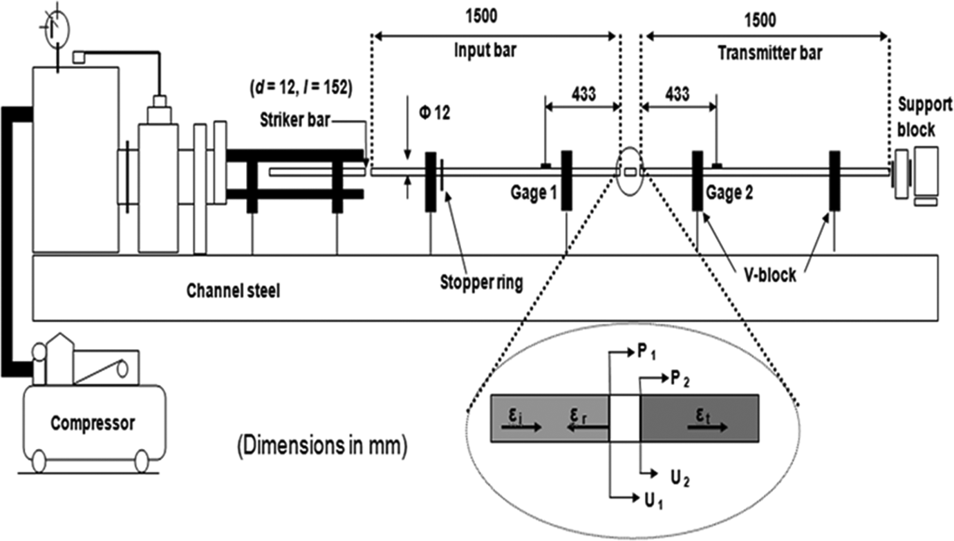
SHPB setup at School of Materials and Mineral Resources Engineering, Universiti Sains Malaysia. SHPB: split-Hopkinson pressure bar.
All assumptions must be considered carefully during the SHPB experiments. For the design of the specimen geometry, the friction effect will be the most important criteria to consider, rather than the specimen thickness. 17 Therefore as suggested by previous researchers, both untreated and treated PP/M-layered silicate composites were cut based on a slenderness ratio of 0.5, so that the diameter and thickness of the specimens were 12 mm and 6 mm, respectively. 13 In practice, there is no specific international standard method for SHPB testing, since every single SHPB apparatus available in the world is slightly different. However, in this study several critical aspects such as apparatus setup, specimen geometry, and data acquisition products were carefully looked into based on the high strain rate testing guidelines provided by the American Society for Metals. 18 Calibration and verification steps were also performed during the high strain rate testing in order to ensure stress equilibrium. Therefore, we performed several calibration methods, reported in our previous studies to fulfill that requirement. 14,15,19 Based on those calibration results, it can be concluded that our SHPB setup is reliable, perfectly aligned, and therefore suitable for further investigation.
During SHPB testing, there are two common methods to determine the strain rate. In general, the strain rate can usually be obtained from the initial slope of the strain rate–time relation. However, in this experiment the strain rate significantly varies with time and is not constant during the impact test, as shown in Figure 2. In this case, Nakai and Yokoyama suggested that the strain rate is calculated by dividing the area under the strain rate curve up to the maximum strain under loading, by the maximum strain. 20 A more recent study by Omar et al. employed a similar approach during their SHPB tests. 13 As a result, the strain rate recorded for the treated PP/M-layered silicate specimen was approximately 900 s−1.
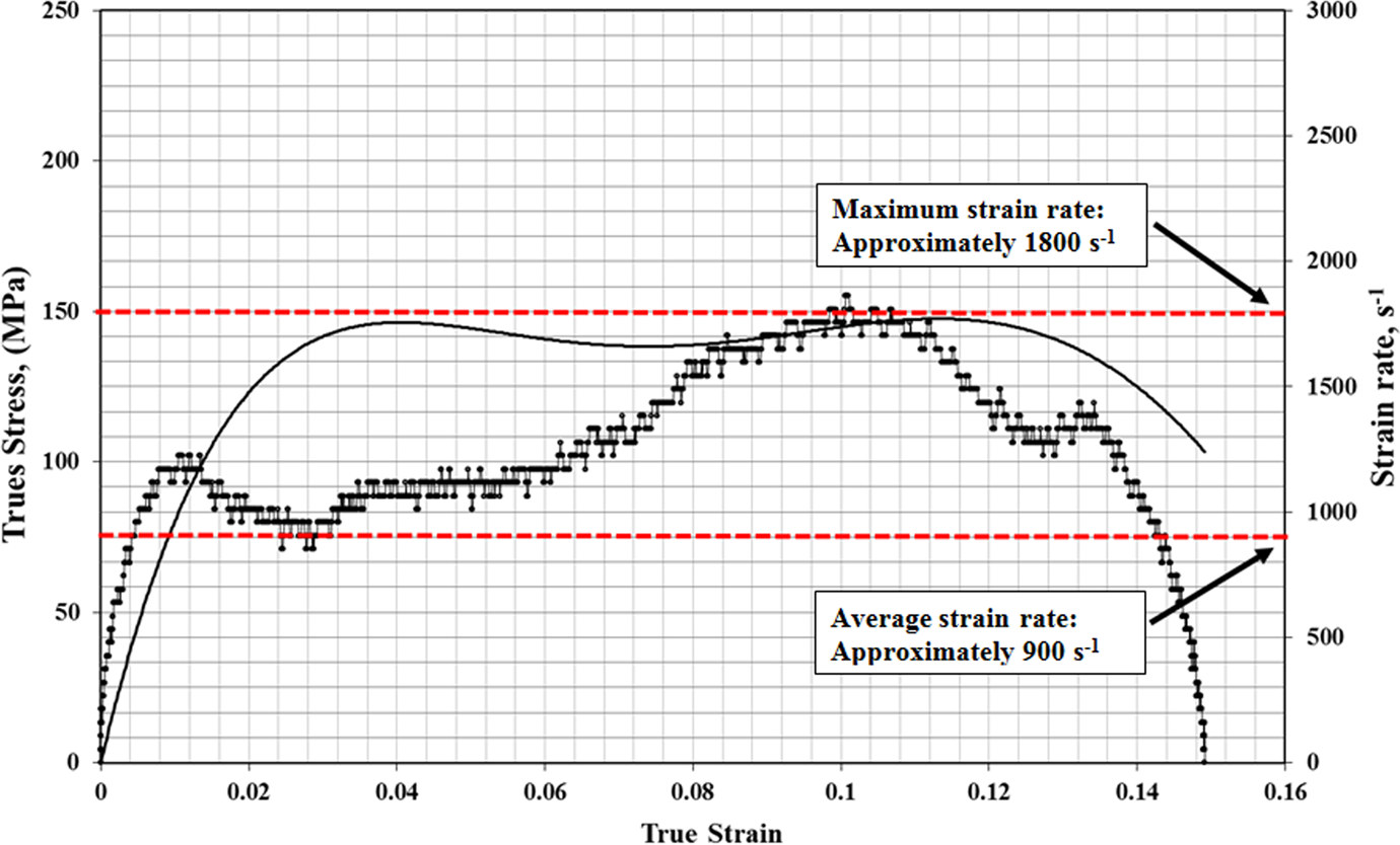
Dynamic true stress–strain and strain rate–strain curves in compression on treated PP/M-layered silicate composites with 14.27 m s−2 of striking velocity. PP: polypropylene; M: muscovite.
Results and discussion
Confirmation of ion exchange treatment
FTIR analysis
It is expected that the ion exchange between K+ and Li+ will occur during the first treatment process, whereas CTA+ ions are expected to replace Li+ ions during the second stage of the ion exchange treatment. In this research, the effectiveness of the ion exchange treatment for M particles has been experimentally proven by the FTIR analysis, as shown in Figure 3. It can be observed that several overlapping and new bands appeared before and after the ion exchange treatment. The bands at around 830 cm−1 are attributed to the octahedral sheets occupied by a trivalent, which is a central atom that has O–H bending bands, which are attributed to the silicate sheet in the M structure. 9 In all FTIR spectra, there is a band at 3620 cm−1 corresponding to the OH group between the tetrahedral and octahedral sheets in the M structure. It can be observed that the transmitter bands which refer to M are similar for all tested specimens, which confirms that the structure of the aluminosilicate layers still remained the same, even after the ion exchange treatment. After the LiNO3 treatment producing Li-M, a new band appeared at 600 cm−1 in the FTIR spectrum, which corresponds to a band of Li+. 11 This indicates that LiNO3 treatments have successfully replaced the interlayer cations of M. 11
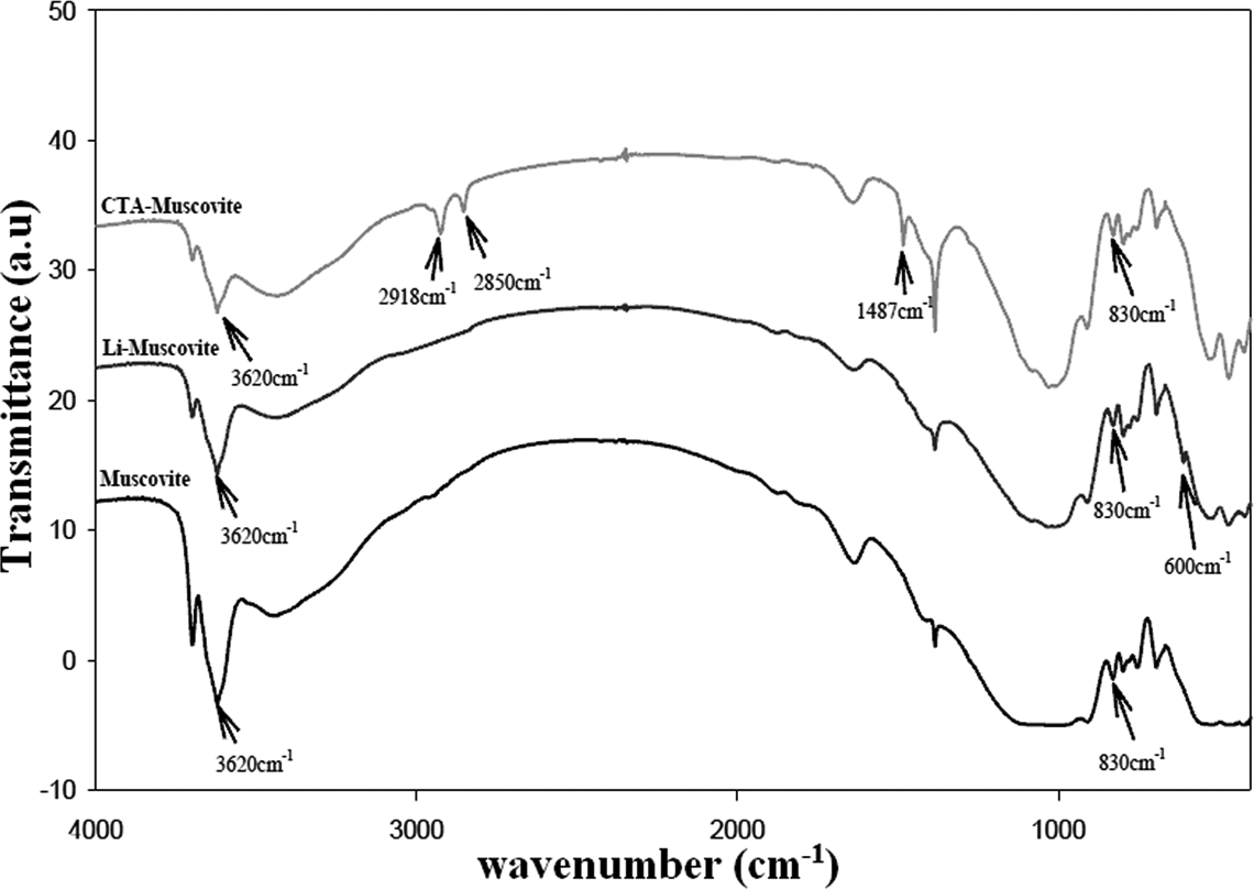
FTIR transmission spectrum of M particles before and after ion exchange treatment. FTIR: Fourier transform infrared; M: muscovite.
After the CTAB ion exchange treatment, new bands at 2918 and 2850 cm−1 appeared in the FTIR spectrum of CTA-M. These two bands are attributed to the CH2 asymmetric (νas CH2) and symmetric (νs CH2) stretching vibration modes of the alkyl chain of CTAB. It is widely accepted that the frequency and width of the CH2 stretching vibration mode are sensitive to the gauche and trans-conformer ratios of methylene chains. 21,22 Meanwhile, the band at 1487 cm−1 is assigned to the asymmetric bending mode of the head methyl group ((CH3)3N+–). 23,24 This indicates that the head groups of CTA+ are anchored to the surface of the aluminosilicate layers of M. Based on the FTIR spectrum described in Figure 3, it can be concluded that the implementation of ion exchange treatment in this study is successful, and therefore further investigation can take place.
XRD analysis
It is expected to distinguish the increment in d-spacing of the silicate layer in M, due to the ion exchange treatment between Li-M and CTAB. This basal spacing increment can be calculated using Bragg’s formula in equation (1). Therefore, the X-ray diffractograms of untreated M, OM, and the PP/M-layered silicate nanocomposite are shown in Figure 4. Meanwhile, the calculated basal spacing values are collected together and summarized in Table 1. From Figure 4(a), it can be seen that the 001 plane diffraction peak of untreated M appears at approximately 2θ = 8.940, corresponding to the interlayer distance of d = 0.99 mm. On the other hand, the 001 plane diffraction peak of OM appears at around 2θ = 7.25 and the interlayer distance of d = 1.22, as shown in Figure 4(b). Cumulatively, a 23% increment in basal spacing of M was recorded after the ion exchange treatment with both LiNO3 and CTAB, which confirms the existence of intercalation between the M clay layers by surfactant molecules. When reinforced with a PP matrix, it was found that composites with OM (PP/OM) recorded lower angles and higher values of basal spacing (d = 1.93 nm) than that of the composite with untreated M (PP/M; d = 1.30 nm). This indicates that more effective intercation and formation of intercalated structures occurred. This phenomenon will be further discussed and understood by the morphology analysis using TEM observation in Figure 5. Theoretically, the shift of the silicate reflection indicates the intercalation of PP chains into galleries of M particles. In addition, it is also believed that the use of a longer surfactant alkyl chain length will further increase the basal spacing of M particles.
The basal spacing of M and PP/M-layered silicate composites.
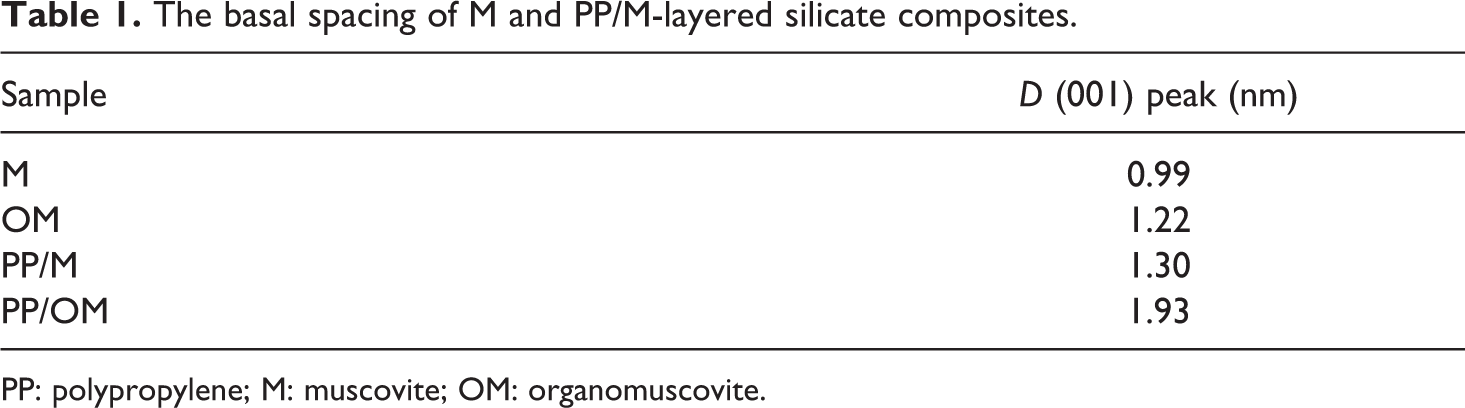
PP: polypropylene; M: muscovite; OM: organomuscovite.
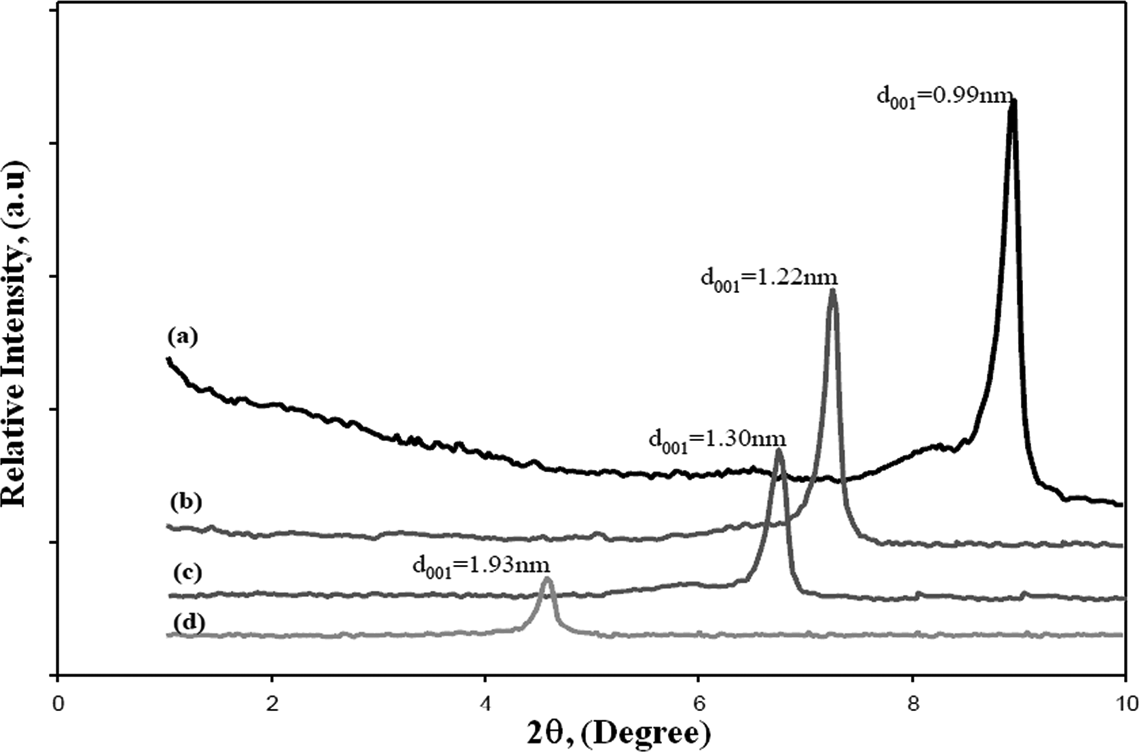
XRD diffractogram of (a) untreated M, (b) OM, (c) PP/M, and (d) PP/OM. XRD: X-ray diffraction; M: muscovite; OM: organomuscovite; PP: polypropylene.
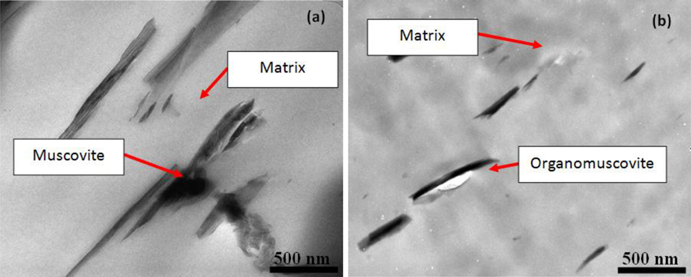
TEM micrographs of (a) 5 wt% PP/M and (b) 5 wt% PP/OM-layered silicate composites. TEM: transmission electron microscopy; M: muscovite; OM: organomuscovite; PP: polypropylene.
Morphology analysis
TEM allows for the direct visualization of intercalation and exfoliation in the nanocomposite structure in a much smaller region than is explored by XRD. The TEM micrographs of both untreated and treated PP/M-layered silicate composites are shown in Figure 5. From Figures 5(a) and (b), it was observed that PP/OM composites show good dispersion and orientation of organolayers, whereas untreated PP/M composites contain larger tactoids. In combination with XRD results, it can be assumed that OM layers were homogenously dispersed within the PP matrix and formed an intercalated structure. Qiao et al. speculated that the modification of clay with LiNO3 and CTAB had lowered the electrostatic interactions between the clay layers and enlarged their intragallery spacing, forming an intercalated structure and efficient dispersion of the clay particles. 25
Stress/strain characteristics
It is widely accepted that the resulting stress/strain curve or diagram gives a direct indication of material characterization. This knowledge is also important, in order to provide a preliminary overview of a material’s mechanical properties including yield behavior, strength, and stiffness. The compressive stress/strain curves of PP/M-layered silicate composites with untreated and treated M particles were investigated under strain rates of 0.01, 0.1, 600, 950, and 1100 s−1 and are summarized in Figures 6(a) and (b). Typically, it can be observed that both PP/M-layered silicate composites are identical in terms of their stress/strain behavior, which can be categorized as ductile. These are typical features and are similar to those reported for many glassy polymers. 26,27 However, the magnitude of ductility is different from one another. Apart from that, it can be clearly observed that the strain rate also makes a significant contribution in creating the stress/strain features of both the tested specimens, where the flow stresses increase gradually with an increasing strain rate. For example, at a specific strain of 0.01, the PP-reinforced untreated M recorded approximately 12, 59, and 13 MPa increments of stress, for 0.01 to 0.1 s−1, 0.1 to 650 s−1, and 650 to 1100 s−1 strain rates, respectively. Meanwhile, PP-reinforced OM recorded approximately a 4, 44, and 44 MPa stress increment, under a similar range of strain rates. The increment was attributed to the viscoelastic nature of the PP itself. 28 Omar et al. proved experimentally that the strain rate altered the glass transition of the PP domain from static to dynamic loading. 28 This shifting phenomenon significantly influenced the intermolecular interaction in the amorphous region of the PP, which begins to pose significant resistance toward deformation. As a result, both untreated and treated PP/M-layered silicate composites become stronger with increasing strain rates.
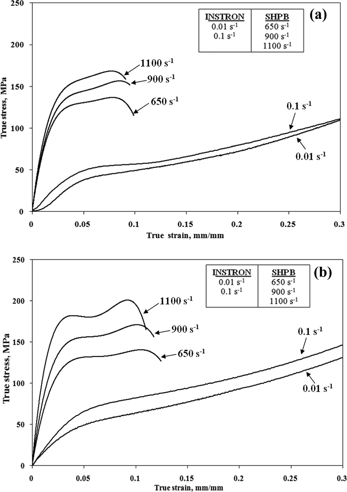
Typical true stress/strain curves of both (a) PP/M and (b) PP/OM-layered silicate composites under a wide range of strain rates. M: muscovite; OM: organomuscovite; PP: polypropylene.
Yield behavior
Yield behavior has become the most common property reported for structural materials, due to the ease and relative accuracy of its measurement. Normally, the yield point reacts as a statistical boundary that separates the elastic and plastic regions. It would be of interest to determine the stress and strain values at the yield point, so that we can determine the effect of the filler treatment on the elastic deformation of both treated and untreated PP/M-layered silicate composites. Therefore, to further clarify the strengthening effect of filler treatment under a wide range of strain rates, the yield stress and strain values were determined and are illustrated in Figure 7. In this experiment, the yield stress values were measured based on the 0.2% offset of the yield strain. It can be seen that both tested specimens showed an increment pattern, in terms of yield strength under increasing strain rates. However, the yield strain values show a contrary trend, where it has decreased significantly with increasing strain rates. This decrement pattern was attributed to the increase in adiabatic temperature within the samples, as polymeric specimens exhibit poor heat transfer. During deformation, generated heat will accumulate within the specimen body and make the material more brittle and therefore weaker. Another reason for this phenomenon was discussed by Nakai and Yokoyama. 20 They speculated that the decrement of yield strain was closely related to the accumulated microdamage during deformation, where more ruptures have to take place in order to adapt to larger deformations at higher strain rates. 20 The combination of both effects contributes to the decrement of yield strain values with increasing strain rate.
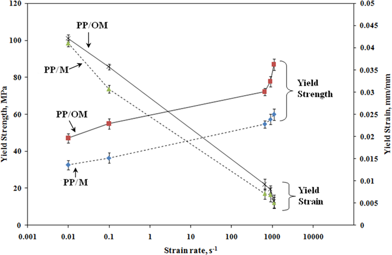
Yield behavior of PP/M and PP/OM-layered silicate composites under various levels of strain rates. M: muscovite; OM: organomuscovite; PP: polypropylene.
Apart from the strain rate effect, the modification of M particles had also influenced the yield behavior of the tested composites. As can be seen in Figure 7, the PP/OM showed higher yield strength and yield strain values than PP/M. Cumulatively, PP/OM specimens recorded a yield stress increment of approximately 19–20 MPa compared with PP/M specimens, when subjected to static and dynamic stresses under 0.1 and 900 s−1, respectively. Meanwhile, the yield strain values for PP/OM specimens recorded an increment of approximately 5 × 10⁻³ and 1.7 × 10 3 under the same strain rates. This increment pattern of yield strength was driven by the better dispersion of layered silicate within the PP matrix for OM, which had previously been proved in the TEM observation, as shown in Figure 5. The better dispersion of OM particles had optimized the stress transfer mechanism between matrix and filler and therefore increased the yield strength. 29 At a high M loading of about 5%, PP reinforced with untreated M may face difficulty and have a agglomeration issue where there is an overlap between one M flake to another, as several misaligned flakes, or flakes stacked on top of each other, act as a stress concentrator. 30 These stress concentrators will restrict the deformation of the PP matrix during loading, and therefore lead to more brittle behavior at lower yield strain values.
Strength and stiffness properties
Strength is referred to as a material’s ability to withstand load, whereas, stiffness is a term to describe the force needed to achieve a certain deformation of a structure. 31,32 In current practice, these two criteria have rapidly become an important assessment for the evaluation of material performance. The ultimate compressive strength (UCS) and the compression modulus of both PP/M-layered silicate composites were investigated under a wide range of strain rates and the results obtained are demonstrated in Figures 8 and 9. From the bar graph shown in Figure 8, it can be observed that the UCS values of both specimens increased steadily with an increasing strain rate. The results are in line with the increment of flow stresses for stress/strain characteristics. Omar and his co-workers had experimentally proved that the viscoelastic properties of PP-based composites had changed, from a rubber-like behavior at a static loading of 0.0001 s−1 to a glass-like behavior at a dynamic loading of 1000 s−1, using dynamic mechanical analysis. 28 This transition from a static to a dynamic condition alters the intermolecular interaction in the amorphous domains of the PP matrix and makes the composite become stronger. From the point of view of the effect of filler modification, it is interesting to note that the PP/OM composite shows higher UCS values than the PP/M composite, for all tested strain rates. It was reported that the CTAB ion treatment has reduced the surface energy of M silicate and this indirectly improves the wetting between M particles and the PP matrix. 3,9 This will also provide better interfacial adhesion between PP and M particles and consequently give a better strength performance. 3,9 These factors account for the greater strength performance of PP/OM composites than their counterpart.
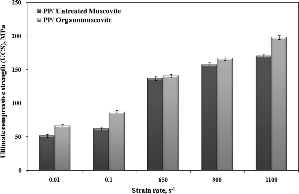
The UCS of PP/M-layered silicate composites under various levels of strain rates investigated. M: muscovite; PP: polypropylene; UCS: ultimate compressive strength.
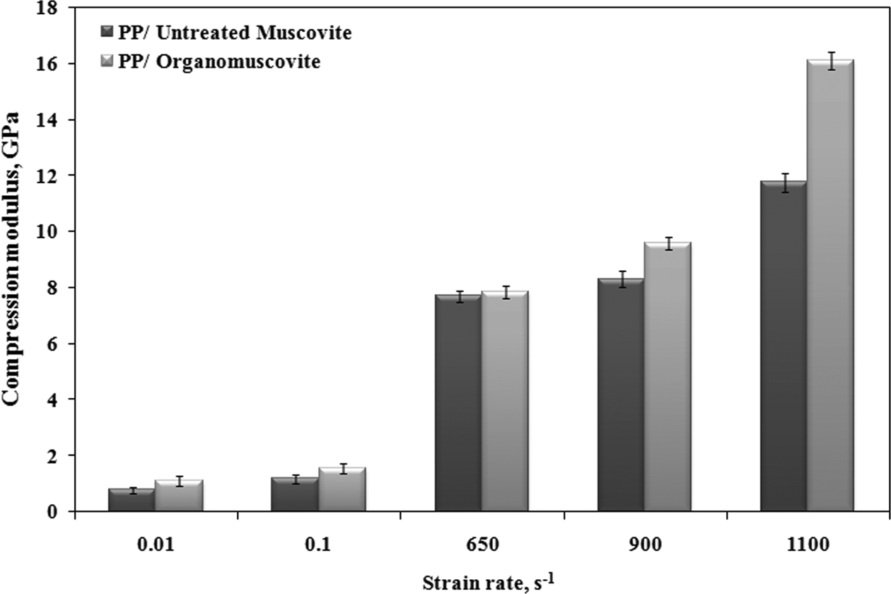
The compression modulus of PP/M-layered silicate composites under various levels of strain rates investigated. M: muscovite; PP: polypropylene.
Further analysis was carried out on the stiffness properties of the PP/M-layered silicate composites, as depicted in Figure 9. From the bar chart it is clearly seen that the compression modulus is gradually increased with an increasing strain rate. This finding is consistent with the results reported by Omar et al. with a similar composite system. 15 They speculated that the increment was attributed to mobility of the polymer chains during deformation. At higher strain rates, the PP chains are restricted due to insufficient time to reorient themselves, thus enhancing the rigidity modulus of the composite material. 15,33 On the other hand, from the filler treatment viewpoint, it can be observed that PP/OM composites recorded higher compression modulus values compared to PP/M composites, over the wide range of strain rate investigated. This trend was primarily attributed to the reinforcing characteristics of the high aspect ratio of dispersed clay nanolayers. The PP/OM composite with more uniform and well-dispersed M particles within the PP matrix will introduce an additional mechanical strain during loading. 34 This additional mechanical strain will effectively restrict the mobility and deformability of the PP matrix, and make the material stiffer. 34
Strain rate sensitivities and thermal activation volume
The sensitivity of a material is manifested to a certain extent by the magnitude of a reaction experienced by it. In reality, materials will react with external elements and show a certain specific level of sensitivity. This sensitivity parameter can also be correlated with many of the material’s properties, including Young’s modulus, strength, flow stress, and so on. In this study, the strain rate sensitivity has become our primary consideration, due to the fact that one material will react differently from another under various loading rates, which can be positive or negative. Usually rate sensitivity is calculated based on the flow stress recorded by the material up to a specific strain rate.
20,35,36
Therefore, in this study, we took the initiative to calculate strain rate sensitivities using an established parameter, which can be expressed as follows:
20
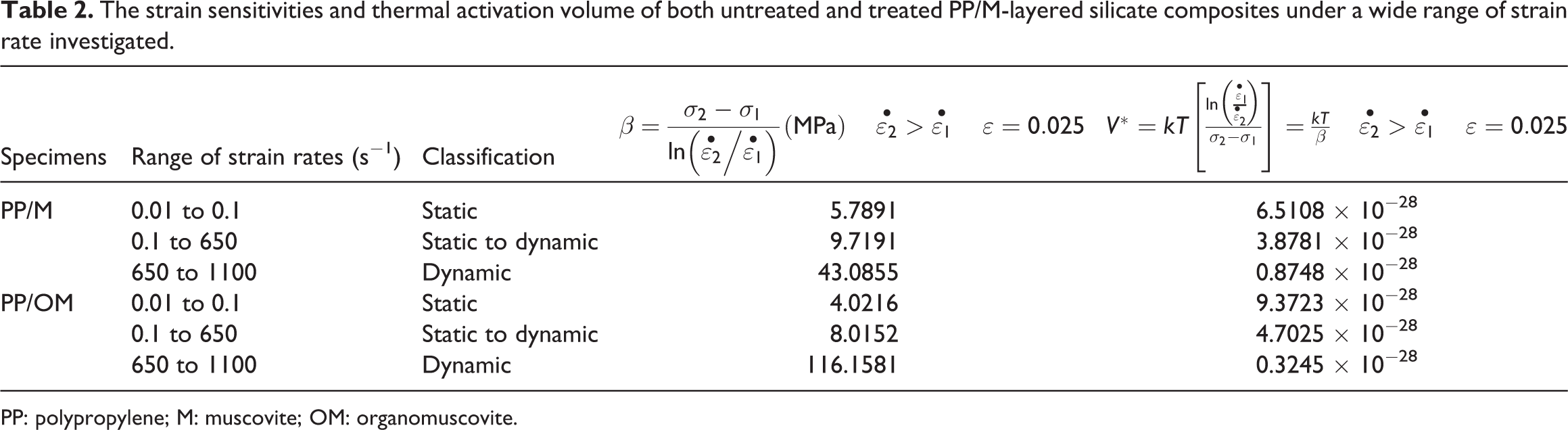
The strain sensitivities and thermal activation volume of both untreated and treated PP/M-layered silicate composites under a wide range of strain rate investigated.
PP: polypropylene; M: muscovite; OM: organomuscovite.
From Table 2, it can be seen that the magnitude of the strain rate sensitivity of both PP/M-layered silicate composites increased significantly with greater loading rates. This phenomenon is attributed to the mobility of the polymer chains during loading. Theoretically, at higher strain rates, higher flow stress is required to perform deformation, since the mobility of the polymer chains is restricted. 38,39 This increment of flow stress for a given strain will consistently increase the rate of sensitivity of a material. Interestingly, the thermal activation volume shows a contrary trend to an increasing strain rate. White speculated that the thermal activation volume of a polymer is related to the free volume between polymer chains structures, which is influenced by the localized motions of segments or possibly side groups of polymer chains. 40 Since the mobility of the molecular chains is restricted at a high strain rate, it will therefore contribute to the lower thermal activation volume of both the tested PP/M-layered silicate composites. At a low strain rate, the entanglement of the polymer chains is higher, therefore increasing the thermal activation volume. On the other hand, based on the results reported in Table 2, it can be preconcluded that the treatment of filler does not have any significant relationship to the sensitivity rate or the thermal activation volume under the wide range of strains investigated.
Absorbed energy
Theoretically, the energy absorption capacity is determined by measuring the area under the stress/strain curve, up to a certain specific strain. 41 This information is important, in order to measure the energy required for the material to perform a specific deformation. Therefore, the capacity of the absorbed energy has become our primary consideration in the present study. We calculated the strain energy of both the PP/M-layered silicate specimens up to 0.025 of strain, as illustrated in Figure 10. It was observed that absorbed energy accumulates steadily with increasing strain rates. This finding is in line with results reported by Yi et al., and the authors believe that the increment of absorbed energy is attributable to the increase of flow stress, initiation strain, and propagation strain at higher strain rates. 42 The tested specimens absorbed more energy at higher strain rates in order to perform deformation, since their molecular mobility was initially restricted. On the other hand, the filler treatment had also influenced the absorbed energy capability of both types of test specimen. As can be seen in Figure 10, the PP/OM specimens recorded a higher energy absorption capacity than that of the PP/M specimens for all strain rates tested. This phenomenon is closely related to the existence of additional mechanical strain for PP/OM composites, as discussed previously. More energy is required up to certain extent, for the PP/OM composites to break the resistance to mechanical strain, in order to perform deformation. This is the main reason why PP/OM composites record a higher energy absorption capacity than PP/M composites for all tested strain rates.
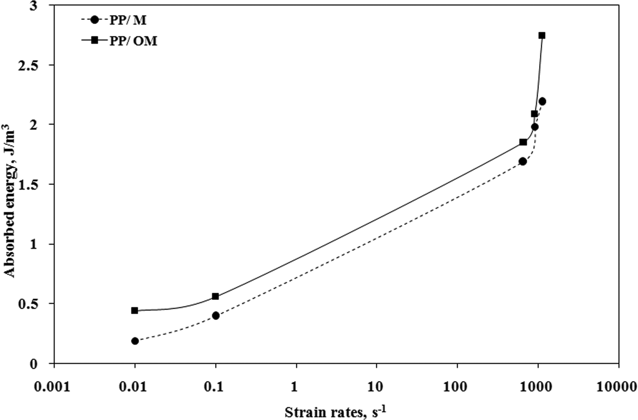
The absorbed energy of PP/M-layered silicate composites under a wide range of strain rate investigated. M: muscovite; PP: polypropylene.
Postdamage analysis
Postdamage analysis was performed using scanning electron microscopy apparatus, as illustrated in Figures 11(a) and (b). These figures show the SEM micrograph of the dynamic compression fracture of both PP/M-layered silicate composites, at a dynamic loading of 900 s−1. From fractographic analysis, it was observed that a lot of cavitation and holes appear on the PP/M specimen surface. Moreover, the state of the M dispersion within the PP matrix for PP/M specimens is not good, compared with PP/OM specimens. Visually, from the fracture surface of PP/M composites, it can be clearly seen that M particles tend to stack up on top of each other, thus acting as a stress concentrator. 30 This stress concentrator conveyed by the voids and holes did not appear on the fracture surface of PP/OM composites. Typically, the existence of stress concentrators will slightly disturb the effectiveness of the stress transfer between the matrix and the muscovite particles, and vice versa. 9 This observation is in agreement with the explanations in Figures 7 to 9, where the composite with untreated M recorded lower compression properties in terms of yield behavior, strength, and stiffness, compared to the composite with OM.
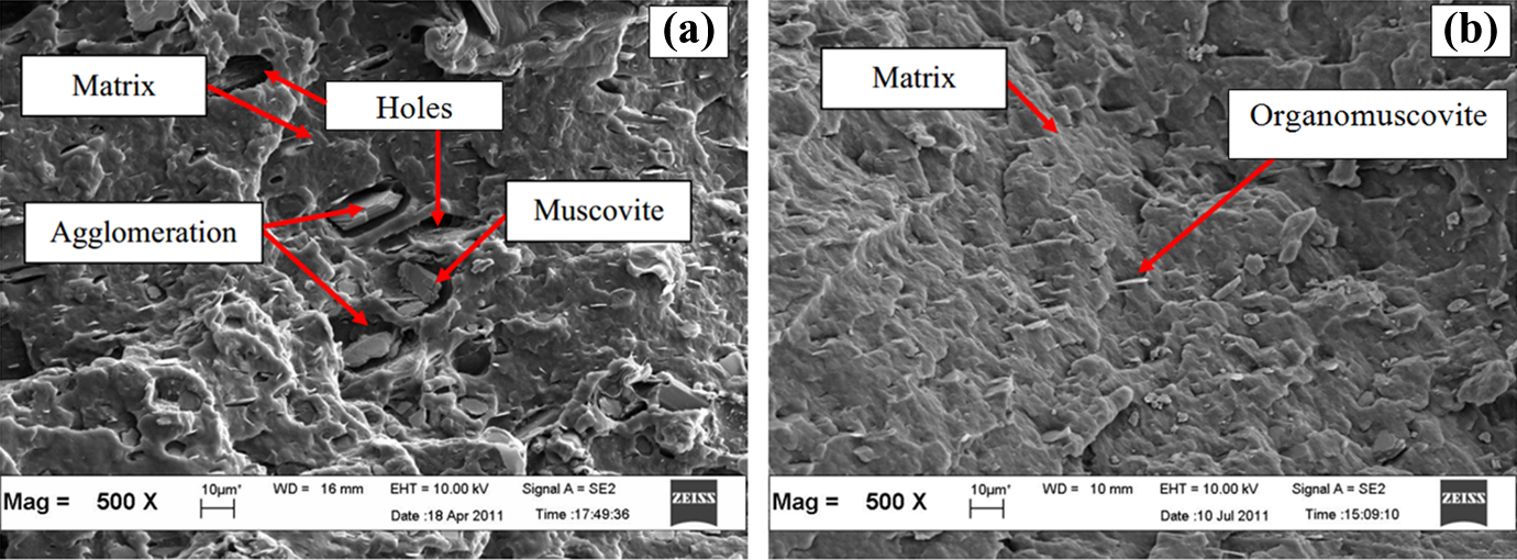
The FESEM images of (a) PP/M and (b) PP/OM-layered silicate composites under 900 s−1 of strain rate. FESEM: field-emission scanning electron microscopy.
Conclusion
In this study, M-layered silicate composites were developed based on PP as the matrix and M as a filler. M particles were treated with LiNO3 and CTAB as a surfactant, through an ion exchange treatment that produced OM. For comparison purposes, static and dynamic compression tests were performed on both of the PP/M-layered silicate composites, up to nearly 1100 s−1 using a universal testing machine and SHPB apparatus. From the results, the following conclusions can be drawn.
The effectiveness of ion exchange treatment on M particles was successfully proven using FTIR, XRD, and TEM results.
Generally, both the tested PP/M-layered silicate composites display similar stress/strain curve characteristics, which can be categorized into the ductile behavior class.
The mechanical properties of both the tested PP/M-layered silicate composites show great dependency on the strain rate applied. The yield stress, compression modulus, ultimate compressive strength, and absorbed energy increased proportionally when the strain rate was increased. However, the yield strain shows a contradictory pattern, where it gradually decreased when an increased strain rate was applied.
The treatment of M filler had a beneficial effect on the mechanical properties of the PP/M-layered silicate composites. It was found that PP/OM composites with better dispersion of M particles exhibit better mechanical performance in terms of yield behavior, strength, rigidity, and absorbed energy properties, compared with PP/M, under a wide range of strain rates that were investigated.
The strain rate sensitivity of both the tested PP/M-layered silicate composites was significantly higher with increased strain rates, whereas the thermal activation values showed a contrary trend.
Postdamage analysis of both the tested PP/M-layered silicate composites is consistent with the results reported for mechanical properties, where PP/M shows massive plastic deformation with the existence of holes and cavitation that may react as a stress concentrator and reduce the mechanical properties of this composite.
Footnotes
Declaration of Conflicting Interests
The author(s) declared no potential conflicts of interest with respect to the research, authorship, and/or publication of this article.
Funding
The author(s) disclosed receipt of the following financial support for the research, authorship, and/or publication of this article: The authors would like to acknowledge the Universiti Malaysia Perlis (UniMAP Grant no: 9017-00014 and 9003-00390) and Universiti Sains Malaysia (USM Grant no: 1001/PBAHAN/8043057 and 811070) for sponsoring and giving financial assistance during this research work.