
Abstract
In this article, a newly developed model is utilized to simulate the strain-rate-dependent constitutive equation of graphene/polypropylene nanocomposites, using the mechanical properties of the constituent materials of nanocomposites. The model is a combination of the micromechanics and Goldberg models called strain-rate-dependent micromechanics (SRDM) model. The Johnson-Cook material model is used by the explicit finite element code LS-DYNA to simulate the strain-rate-dependent mechanical behavior of the standard tensile test specimen made of graphene/polypropylene nanocomposites under dynamic loading and its constants are calculated by the SRDM model. Polypropylene reinforced with 0.5, 1.0, and 2.0 wt% graphene sheets were prepared via coating polypropylene with graphene particles. Then, by melt blending in a twin-screw extruder followed by an injection molding process, the nanocomposite samples are manufactured. Good enhancements of Young’s modulus and yield stress at very low graphene contents are achieved. To evaluate the current model, the results are compared with the experimental result of the standard tensile test specimen. A good agreement between the experimental data and the SRDM model is achieved.
Introduction
Owing to the large interfacial area, high aspect ratio, and small interparticle distance of graphene, it has emerged as an interesting material with exceptionally attractive properties that have recently drawn intense attention from researchers. 1–3 Despite the extraordinary potential of being a promising nano-reinforcement, achieving a homogenous dispersion of graphene sheets in a polymeric matrix is still a research topic. In recent years, different processing methods have been explored to solve the problem of graphene dispersion. When it comes to polypropylene (PP), the solution method and melt mixing method are two more common methods among the reported ones. These methods are based on entering PP chains between the layers of graphene. In the solution method, a solvent is used to dissolve the polymer and the nanoparticles are dispersed in the matrix, then the solvent is dried. 4,5 However, in the case of PP, the solution technique needs high amounts of solvents, and hence it is not considered an appropriate practical method. 6 In the melt mixing method, under the high shear of an extruder, polymer and nanofillers are mixed together. This method is more economical than the solution method; however, it is more prone to form agglomeration of nanoparticles in the polymeric matrix. To overcome the dispersion problem of exfoliated graphite in the PP, a new method has been used by Kalaitzidou et al., 6 that is, precoating PP with exfoliated graphite before the melt mixing process. The results indicated a better performance of resulted composites than those obtained using the other fabrication methods. In the literature, there are few studies about the behavior of nanocomposites under different strain rates. Ingram et al. 7 studied the tensile behavior of PP carbon nanofibers at the strain rates of 0.02–2 min−1. They showed that the pure PP and its nanocomposites have strain-rate-strengthening behavior and their tensile modulus and yield strength are increased by increasing the strain rate. The loading rate and temperature effects on the mechanical behavior of multiwall carbon nanotubes /PP nanocomposites are investigated by Bao and Tjong 8 who reported similar behavior.
Recently, Shokrieh et al. 9 by combining a micromechanics model (the Halpin-Tsai model 10 ) and a strain-rate-dependent material model (the Goldberg model 11 ) developed a model called strain-rate-dependent micromechanics (SRDM). In the present research, the mechanical properties of the PP are characterized by performing some experiments. The results of these experiments are used as the inputs for the SRDM model. Furthermore, the results of the SRDM model are used as the inputs for the Johnson-Cook material model. 12 Finally, using the results of the Johnson-Cook material model, the explicit finite element code LS-DYNA 13 is utilized to predict the tensile strain-rate-dependent behavior of graphene/PP nanocomposites. The result obtained by the mentioned strategy is evaluated with the result of the standard tensile test of graphene/PP nanocomposites.
Experimental studies
Raw materials
Isotactic PP homopolymer having a melt flow index of 25 g 10 min−1 according to ASTM D-1238 was supplied in powder form by Shazand (Arak) Petrochemical Corporation (Iran). Nano-graphene platelets (NGPs) were obtained from XG Sciences, Inc. (Missouri, USA) NGP has a thickness and a density of 6–8 nm and 2.2 g cm−3, respectively.
Preparation of PP-coated graphene
In this research, to have a uniform distribution of the nano-graphene in the PP, the method developed by Kalaitzidou et al. 6 for distribution of exfoliated graphite in PP is used. First, graphene is dispersed in isopropyl alcohol by sonication for 30 min at room temperature. After the layers of graphene got opened and distributed in the alcohol, the PP powder is added to the solution. Subsequent to mixing of graphene and the PP powder, the solvent is removed using a rotary evaporator and then using an oven in the absence of vacuum; it is dried completely at 110°C, resulting in a complete coating of PP powder particles with graphene.
Fabrication of graphene/PP nanocomposites
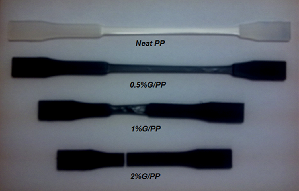
After coating PP with graphene particles, an intermeshing corotating ZSK twin-screw extruder operating at 180°C for 5 min at a screw speed of 250 rpm was used for melt mixing. The residence time and screw speed are determined by trial and error in order to obtain a good combination of residence time and shear rate, which results in a good dispersion of graphene in the chains of melted PP. The nanocomposite flows out of the extruder in the form of noodle stream and got cold in a bath of water. Then they were pelletized in a pelletizer and resulting chopped nanocomposites (Figure 1) are dried in a vacuum oven for about 2 h at 110°C in order to remove all possibly existed moistures. Then dried chopped nanocomposites are used in an injection molding machine with processing temperatures between 180 and 200°C and molded into standard ASTM D638 Type-I dog bone specimens. The nanocomposites were prepared in three different graphene contents. Three different weight percentages of graphene, namely 0.5, 1, and 2 wt% were used to investigate the effect of different graphene contents on the tensile strain-rate-dependent behavior of the PP. After fabricating the specimens, they were stored at room temperature for about 11 days. The schematic of tensile test specimen and tensile specimens after fabrication are shown in Figures 2 and 3, respectively.
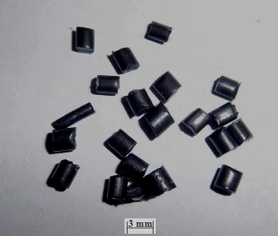
Chopped graphene/polypropylene nanocomposites.
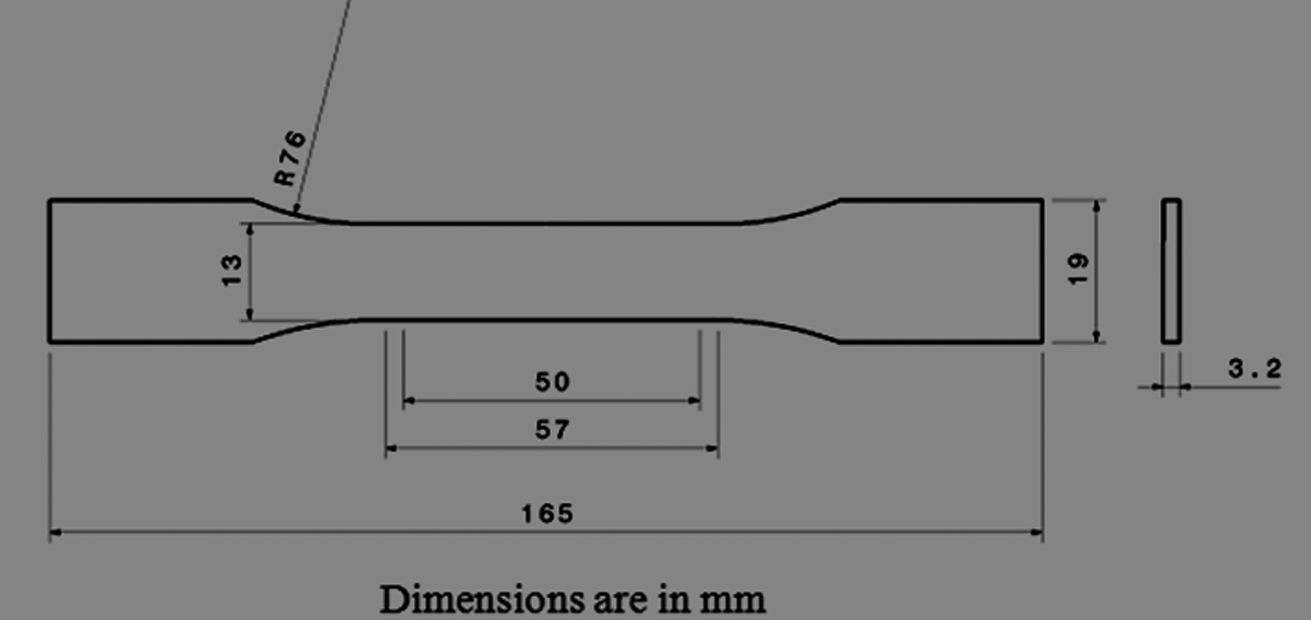
Schematic of tensile test specimen.
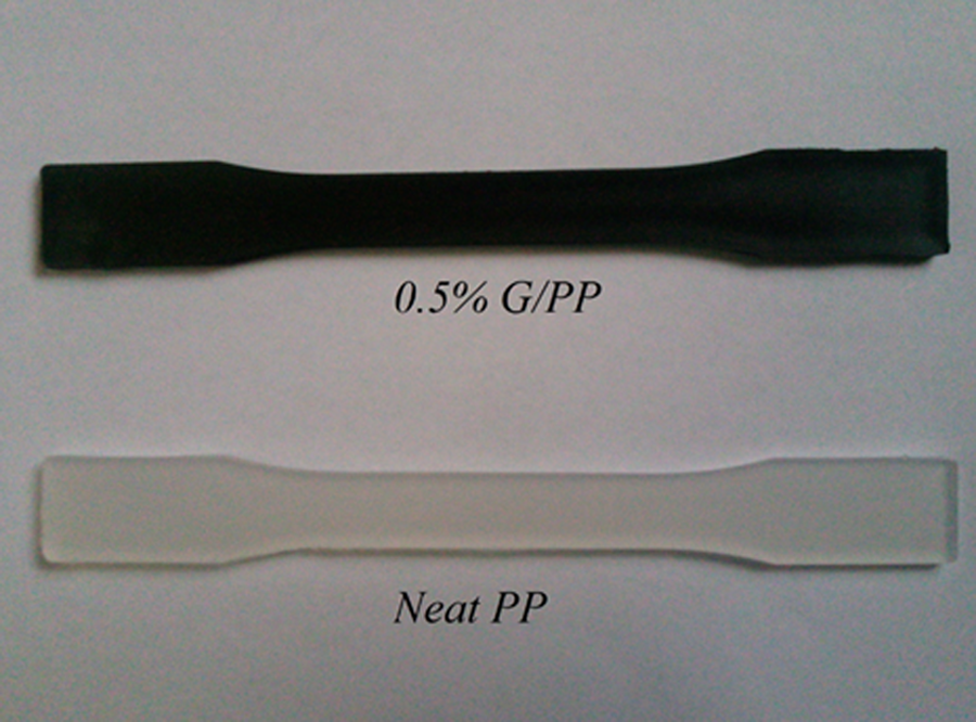
Tensile test specimens.
Tensile behavior of graphene/PP nanocomposites
Figure 4 shows the stress–strain curves of PP at different graphene contents. Five specimens are tested at each graphene loading and their average values are plotted in Figure 4. As it is obvious in Figure 4, adding graphene to the PP caused a good enhancement in the Young’s modulus, yield stress, and ultimate tensile strength at low graphene contents, so that at 0.5 wt.% of graphene loading, 21% increase in the yield strength and 34% increase in the Young’s modulus of PP are achieved.
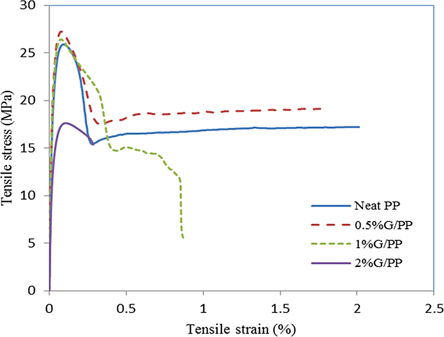
Stress–strain behavior of graphene/PP nanocomposites with different graphene contents. PP: polypropylene.
Variation in yield stress and Young’s modulus at various graphene loading are shown in Figures 5 and 6. It is observed that by adding graphene into the PP, the yield stress and Young’s modulus first increased and then by increasing the graphene content, they decreased. The presence of graphene and their proper dispersion in the polymeric matrix are the causes of initial increase in the yield stress and Young’s modulus values. The best enhancement was observed at 0.5 wt.% graphene loading. These good dispersed NGPs force the crack to deviate from its propagation path; and based on their good adhesion with the PP, they act as good load bearing agents. In the higher graphene content, the decrease in the yield stress and Young’s modulus values can be attributed to the agglomeration of graphene sheets, which causes high stress concentration in nanocomposites. This behavior is in agreement with the results reported by Pingan et al. 14
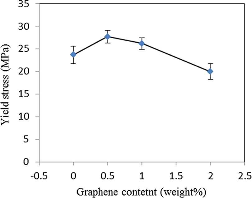
Effect of graphene content on the yield stress of graphene/PP nanocomposites. PP: polypropylene.
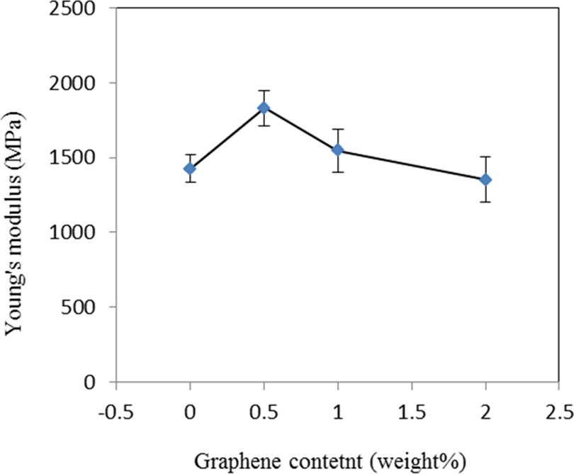
Effect of graphene content on the Young’s modulus of graphene/PP nanocomposites. PP: polypropylene.
Specimens after tensile tests are shown in Figure 7.
Tensile specimens after test.
Modeling
Strain–rate-dependent constitutive equation of graphene/PP
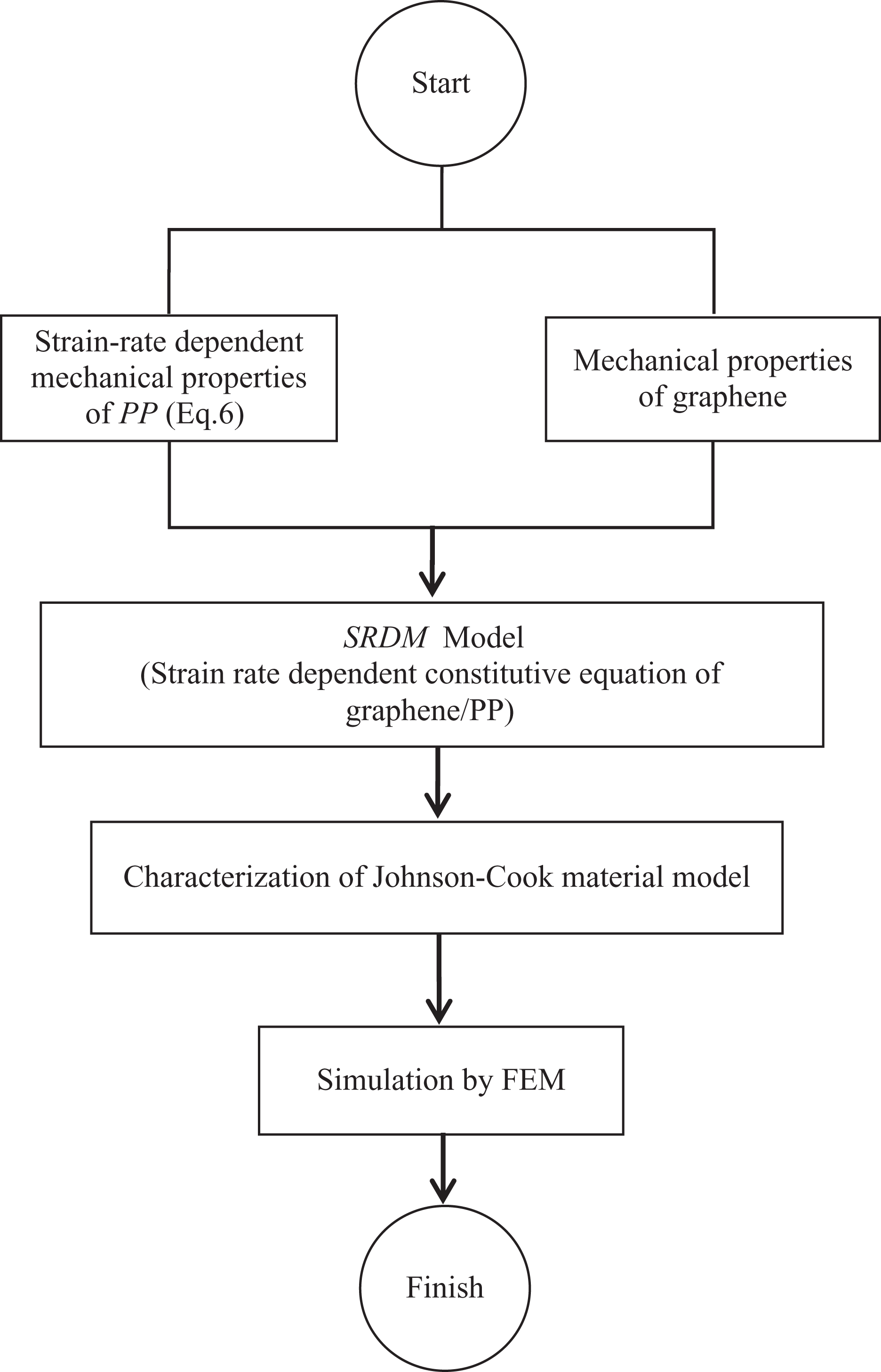
In the current study, the SRDM model 9 is used to predict the constitutive equation of graphene/PP nanocomposites as a function of loading rates. This SRDM model is a combination of the constitutive equation of a polymer (provided by Goldberg 11 ) and a suitable micromechanical model (Halpin-Tsai equation 10 ). The flowchart of the SRDM model to achieve the rate-dependent behavior of graphene/PP nanocomposites is shown in Figure 8. Since, in comparison with the PP, graphene is a rigid material, it has been assumed that the mechanical properties of graphene are not sensitive to the loading rates.
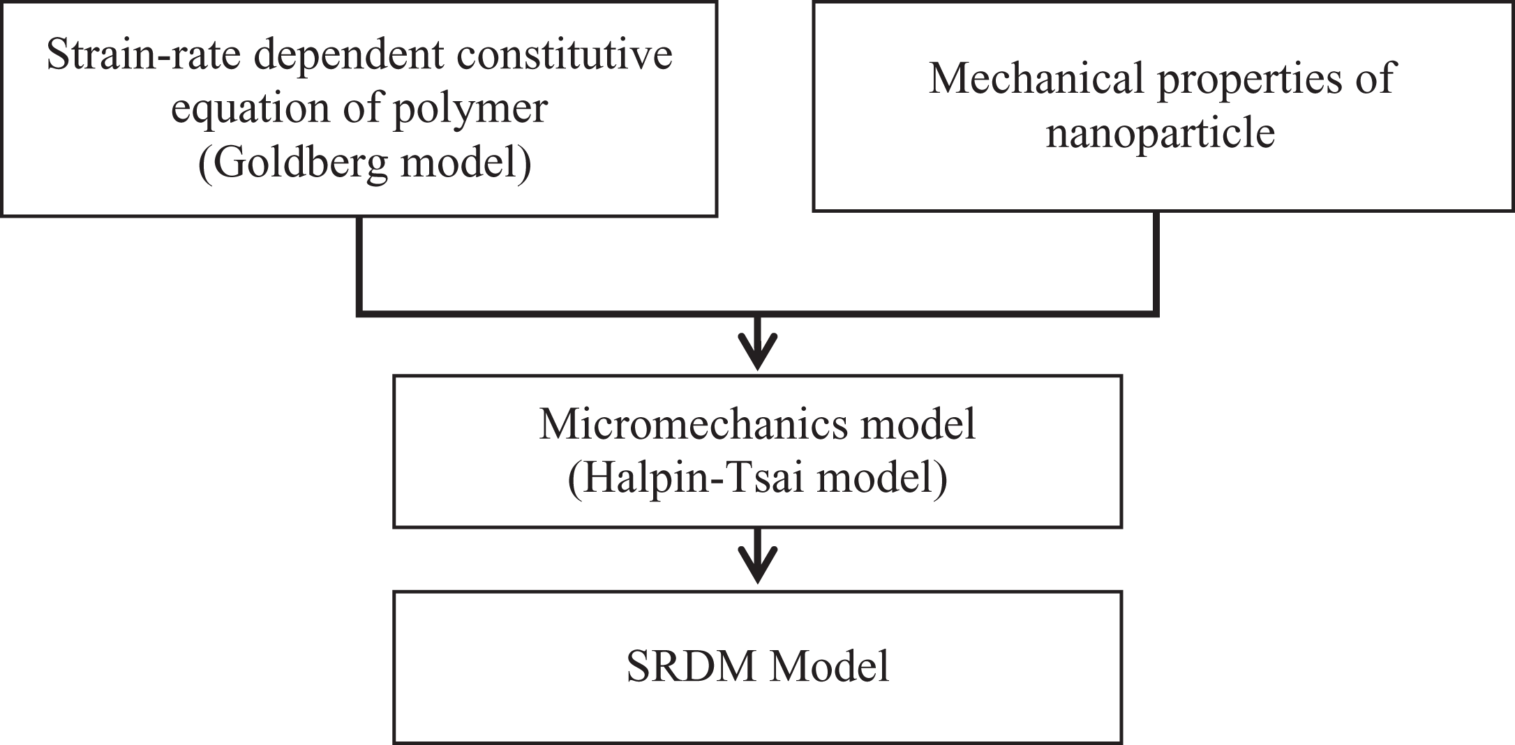
Flowchart of SRDM model to achieve the rate-dependent behavior of graphene/PP nanocomposites. PP: polypropylene; SRDM: strain-rate-dependent micromechanics.
This approach requires material constants of polymers, loading rates, and mechanical properties of nanoparticles as inputs. A combination of these material constants for constituent materials of nanocomposites with a suitable micromechanics method is used to predict the strain-rate-dependent mechanical behavior of graphene/PP nanocomposites for an arbitrary volume fraction of graphene.
Halpin-Tsai micromechanics model
There are some theoretical models that predict the mechanical behavior of a nanocomposite by considering its ingredients properties. One of these models is Halpin-Tsai micromechanics model
10
that predicts the elastic constants of composites using the elastic constants of matrix and the filler. The semiempirical Halpin-Tsai equation is defined as follows:

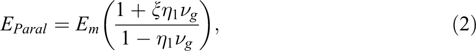
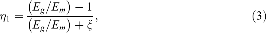
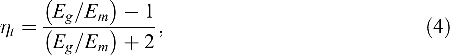
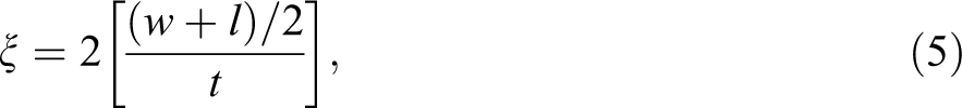
where, Eg and Em represent the Young’s modulus of the graphene and the polymeric matrix, νg is the volume fraction of graphene, the parameter ξ depends on the geometry and boundary conditions of the graphene, where l, w, and t represent the average graphene sheet’s length, width, and thickness.
Constitutive equation of PP
By assuming isotropic behavior for polymers, neglecting temperature and moisture effects, ignoring the nonlinear strain recovery of polymers during unloading, and applying small displacement gradient theory, the modified Goldberg model 11 is developed. This model is applied to capture the nonlinear strain-rate-dependent deformation behavior of polymers.
The first step in characterizing the deformation behavior of polymers such as the PP is separating the total strain into two regions: elastic and inelastic strains. Using initial stiffness properties of polymer and elastic strain, which is the difference between the total and inelastic strains, the required stress can be predicted. The inelastic strain components can be determined as follows
11,15
:
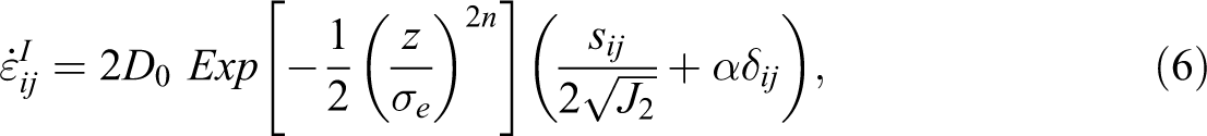
where,

where ασkk
indicates the triaxiality effects. The system of ordinary differential equations for the two state variables z and α can be calculated using the following equations:


where q controls the hardening rate effects of material, and z1
, α1
, z0
, α0
are maximum and initial values of z and α respectively. The term
A computer code developed by Shokrieh et al. 9 is used to find the Goldberg constants and incorporate the Goldberg model with Halpin-Tsai micromechanical model in order to capture the strain–rate-dependent deformation behavior of graphene/PP nanocomposites.
Simulation strategy
In this section, the strategy for simulation of the standard tensile test specimen made of graphene/PP nanocomposites under dynamic loading is explained. In the first step, PP is characterized by proper experiments. Then using mechanical properties of graphene and by applying SRDM model, strain–rate-dependent properties of graphene/PP are calculated. The Johnson-Cook material model is used by the explicit finite element code LS-DYNA. Therefore, in the second step, the material constants of the Johnson-Cook material model are determined by the results of SRDM model. Finally, using the LS-DYNA software, the strain-rate-dependent mechanical behavior of the standard tensile test specimen made of graphene/PP nanocomposites under dynamic loading is simulated. The flowchart of the simulation strategy is shown in Figure 9.
The flowchart of the simulation strategy.
Characterization of the Johnson-Cook material model as an input of the finite element method (FEM)
Johnson and Cook
12
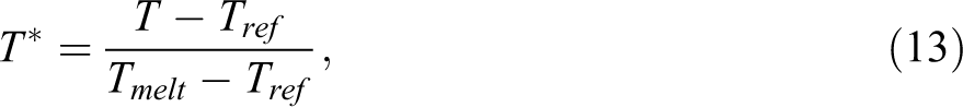
proposed an empirically based constitutive model that expresses the equivalent von Mises flow stress as a function of strain, strain rate, and temperature as follows:

where A, B, C, n, and m are the five material constants. A is the yield stress at reference temperature and reference strain rate, B and n are the strain hardening coefficient and exponent, C is the strain rate sensitivity coefficient, m is thermal softening coefficient, σ is the flow stress, εp
is the equivalent plastic strain,
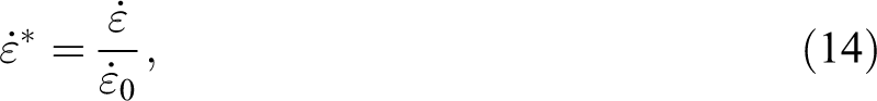
where
In this study, the temperature effect is neglected. So, the Johnson-Cook model is simplified as:

The strain and strain rate are two independent phenomena that can be isolated from each other, so the total effects of strain and strain rate on flow stress can be calculated by multiplying these two terms. This independency is used for determining the material constants of the Johnson-Cook model, and this is discussed in the next section.
Parameter solving
For parameter solving of Johnson-Cook model, first the quasi-static engineering stress–strain curve of PP is needed, which is shown in Figure 4. The value of A is calculated from the yield stress of the quasi-static test curve of neat PP specimens.
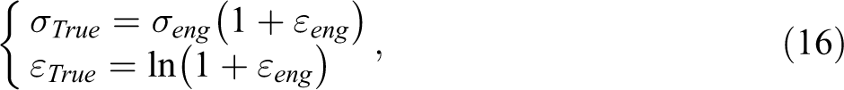
True stress and true strain are calculated from the measured engineering stress (σeng
) and engineering strain (εeng
), using Eq. (16).
Using the above information, the true stress–strain curve of neat PP is calculated (Figure 10).
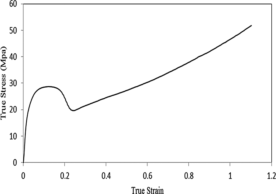
True stress–strain curve of neat PP. PP: polypropylene.
In order to calculate the Goldberg constants, shear stress–strain curves of the PP are obtained from Daiyan et al. 16 Furthermore, for a comparison of the obtained results by the present model, similar strain rates used by Bao and Tjong 8 are used in the present study. Using the Goldberg model, stress–strain curves of neat PP are achieved (Figure 11).
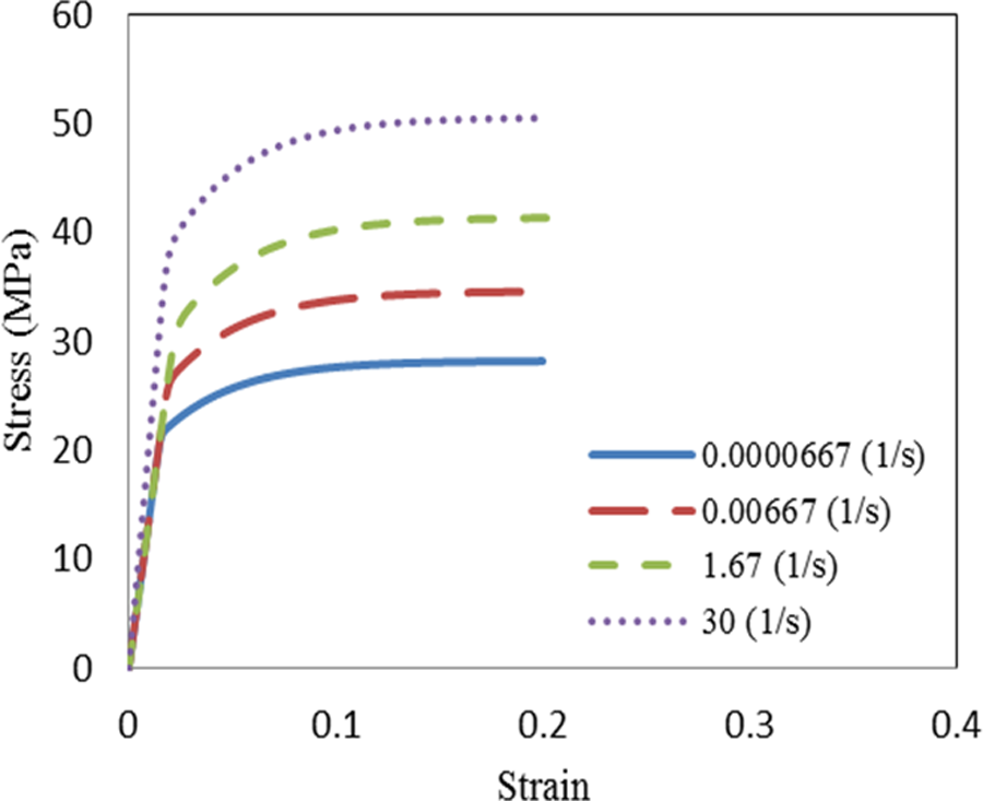
Stress–strain curves of neat PP at different strain rates. PP: polypropylene.
Since the best enhancement in mechanical properties was achieved by adding 0.5 wt% graphene to the PP, 0.5% graphene/PP is considered for the modeling. Using the SRDM model and stress–strain curves of the neat PP (shown in Figure 11), the stress–strain curves of 0.5% graphene/PP at different strain rates are predicted (Figure 12).
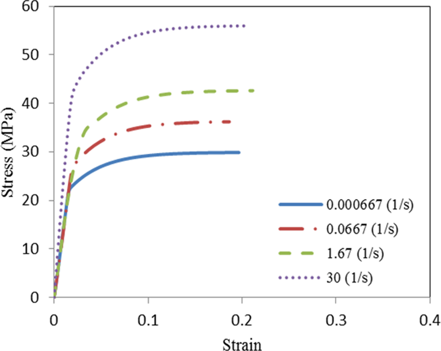
Stress–strain curves of 0.5% graphene/PP nanocomposites at different strain rates. PP: polypropylene.
The plastic strain is determined by subtracting the elastic strain from the true strain using Eq. (17).

where εp
is the plastic strain, εT
is the total true strain, σT
is the true stress, and E is the Young’s modulus of the material. The true plastic stress–strain curve for 0.5% graphene/PP is shown in Figure 10. Rearranging Eq. (15) gives:

Constants B and n are determined from log (plastic stress) versus log (plastic strain) plot as shown in Figure 13.
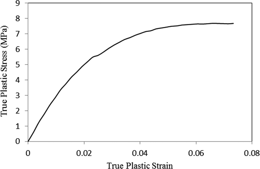
True plastic stress–strain curve for 0.5% graphene/PP nanocomposites. PP: polypropylene.
The constant B in Eq. 18 is calculated from the y-intercept (the point where the straight line in Figure 14 crosses the y-axis), while n is obtained from the slope of the straight line in this figure.
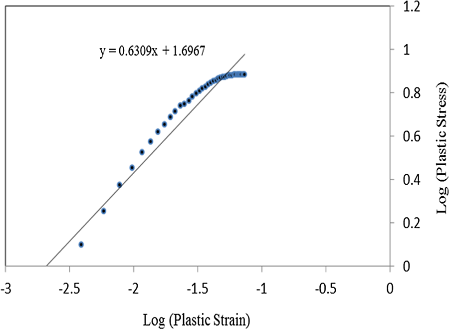
Constants B and n for 0.5% graphene/PP nanocomposites. PP: polypropylene; B: strain hardening coefficient; n: strain hardening exponent.
The constant C is the slope of dynamic/static stress ratios at 2% plastic strain versus the natural log of the strain rate of that test (Figure 15). Table 1 shows values of A, B, C, and n obtained from the above analysis.
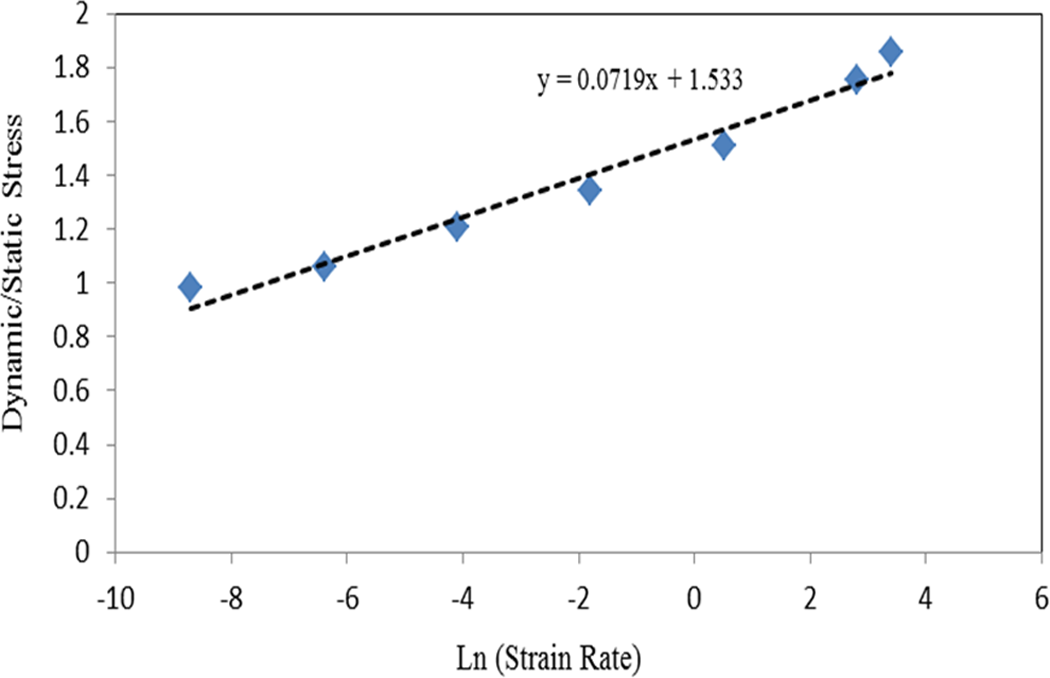
Constant C for 0.5%graphene/PP nanocomposites. PP: polypropylene; C: strain rate sensitivity coefficient.
Material parameters of 0.5% graphene/PP nanocomposites based on the Johnson-Cook model.a
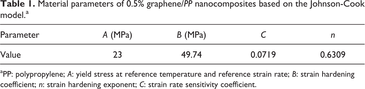
aPP: polypropylene; A: yield stress at reference temperature and reference strain rate; B: strain hardening coefficient; n: strain hardening exponent; C: strain rate sensitivity coefficient.
Simulation the tensile behavior of 0.5% graphene/PP nanocomposites
The explicit finite element code LS-DYNA was used to simulate the tensile strain-rate-dependent behavior of 0.5% graphene/PP nanocomposites. The tensile specimen was fabricated according to ASTM standard D638 Type-I dog bone and was modeled and meshed in LS-DYNA. Figure 16 shows the FEM mesh of the tensile specimen. By considering the symmetry of the specimen, only one-eighth of that was meshed in order to save the computational time. The material model MAT_098 (MAT_SIMPLIFIED_JOHNSON_COOK) is used. A quasi-static tensile test is simulated using solid elements.
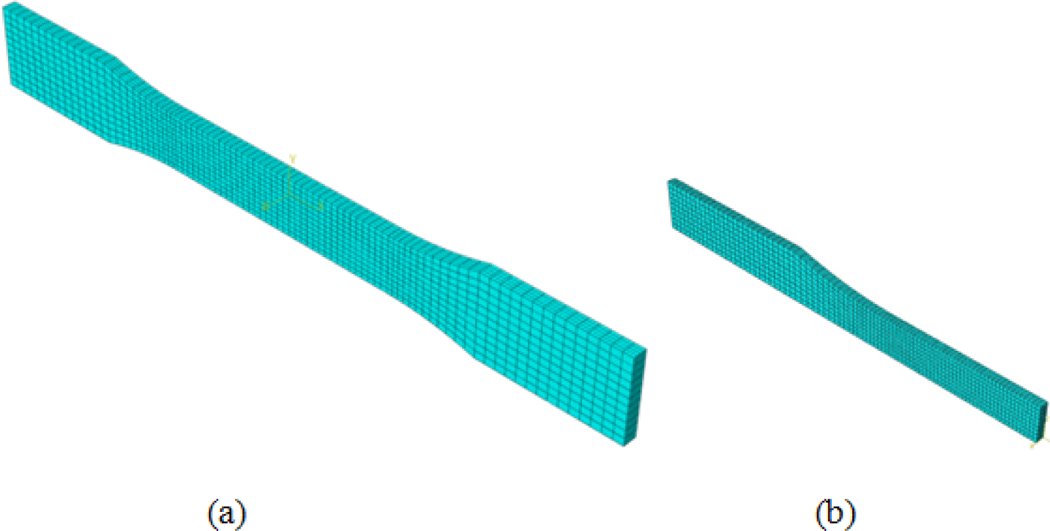
Schematic of (a) FEM tensile sample, (b) One-eighth of FEM sample. FEM: finite element model.
Figure 17 shows a comparison of the stress–strain curves obtained by simulation and experiments for 0.5% graphene/PP nanocomposites. As it is clear in this figure, uniaxial tensile strain-rate-dependent test simulation behavior of 0.5% graphene/PP nanocomposites using the proposed SRDM model showed a good agreement with the result obtained by the experiment.
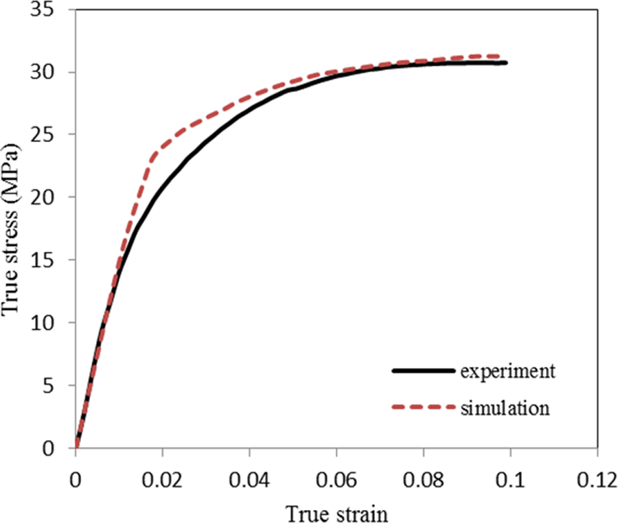
The comparison of stress–strain curve obtained by simulation and experimental results for 0.5%graphene/PP nanocomposites. PP: polypropylene.
Conclusion
In this article, a recently developed model (SRDM model) is used to simulate the strain-rate-dependent tensile behavior of graphene/PP nanocomposites. In comparison with the PP, graphene is a rigid material. Therefore, it has been assumed that the mechanical properties of graphene are not sensitive to the loading rates. Furthermore, the temperature effects are neglected. By coating the PP with graphene and then melt blending in a twin-screw extruder followed by injection molding, nanocomposites with well-dispersed graphene are achieved. The effect of the different graphene contents on the tensile behavior of PP is investigated. Good enhancement of Young’s modulus, yield stress, and ultimate tensile strength at very low graphene contents shows the efficiency of this fabrication method. The Johnson-Cook material model is characterized and used by the LS-DYNA software. It is shown that the results of simulation, performed by a combination of SRDM model and Johnson-Cook material model, are in good agreement with the experimental data. Considering the outcome of this research, it can be claimed that the proposed model is reliable enough to simulate the tensile behavior of graphene/PP nanocomposites under dynamic loading conditions, using mechanical properties of graphene and the neat PP.
Footnotes
Funding
This research received no specific grant from any funding agency in the public, commercial, or not-for-profit sectors.