
Abstract
Thermoplastics with and without fiber-reinforced plastic reinforcement are currently being used in waterfront applications, for example, in piers instead of timber and reinforced concrete pilings. Although the use of thermoplastics as the compression members exists, they have not been used as the flexural members in civil engineering structures such as bridges or building. To be able to safely use these materials as flexural elements in structures, the suitability of the design procedures needs to be investigated. In this study, ultimate strength design procedure similar to the one used in concrete structures was developed for thermoplastic beams. Experimental data were also provided for comparison. Although the needed coefficients used in the procedure need modifications by more experiments, the developed procedure shall be valuable for practicing engineer using familiar procedures of reinforced concrete design.
Introduction
Plastics have been increasingly used in construction projects in recent decades. However, their uses are mostly limited to nonstructural uses, for instance, piping and window frames. In these cases, specific classes of plastics called thermoset plastics are mainly used. Since the failure of thermoset plastics under loads is brittle, they are not very suitable for structural uses. Thermoplastics are promising in a sense that they fail usually in a very ductile mode. The plastics also offer some advantages over conventional construction materials. For instance, reinforced concrete and steel have poor resistance against corrosion in humid environments. Fiber-reinforced plastics (FRPs)/polymers usage in such environments have become more attractive. Another promising material to be used in such environments is thermoplastics.
In addition to conventional construction materials such as steel, wood, and reinforced concrete, plastics and FRP materials are increasingly used in various types of civil engineering structures. Many of these new types of plastic products do not have corrosion problems, are nonmagnetic, and can be made of recycled materials. There are many different forms of structural plastics products available, and the properties of these vary over a wide range. One specific type of material used for manufacturing structural members is known as thermoplastic. Thermoplastics with and without FRP reinforcement are currently being used in waterfront applications, for example, in piers instead of timber and reinforced concrete pilings 1,2 and also as bridge pier protection systems. 3 The term thermoplastic is generally used for the class of plastics that is capable of being repeatedly softened by heat and hardened by cooling. Another important new material is FRPs in the forms of rebar, sectional shapes, and plates. The FRP rebars are used for reinforcing both thermoplastic structural members as well as reinforced concrete members.
Whereas the thermoplastic products and FRP rebars are readily available, often not enough convenient analytical and design procedures are available to make thermoplastics products use in traditional civil engineering applications. One of the goals of this study is to generate useful analytical and experimental results for statically loaded thermoplastic beams with and without FRP rebars. The outcome of this investigation is providing a simplified bending analysis and design procedures for such structural beams.
The flexural behavior of thermoplastic beam in the elastic range was investigated by Mascia. 4 A theoretical model including nonlinearities due to material properties and large rotations in thermoplastic beams and plates were presented by Trantina. 5 Taylor 6 presented a summary of full-scale bending and compression test results on FRP-reinforced thermoplastic products. In these tests by Taylor, while some experiments were conducted to determine the flexural stiffness and compressive strength of thermoplastic products with FRP rebars, a detailed analysis of the flexural or compression behavior of the thermoplastic products was not presented. It was shown by Razzaq et al. 7 that the thermoplastic beams could be designed by a load and resistance factor design (LRFD) procedure. The elastic–plastic stress analyses of thermoplastic composite beams reinforced unidirectionally by steel fibers loaded by bending moments have been performed by researchers. 8 –10
Materials and methods
Thermoplastics are new materials introduced to civil engineering structural applications. Their uses are limited to mostly nonstructural applications due to both their material properties and availability of analytical procedures. The thermoplastics certainly have less structural capacity than reinforced concrete and steel in terms of stiffness and strength. The thermoplastics are also known for undergoing high rates of creep over long periods of sustained loading compared with concrete. 11,12 On the other hand, thermoplastics can be produced at a very low cost especially if they are made out of recycled plastic material. 13 So, this thermoplastic material can be used where the loads are light such as roof beams. In the past, researchers focused on using detailed analytical tools such as finite element modeling approach in their analyses. Although LRFD analysis was proposed as another analytical tool, 7 for the convenience of familiarity of a practicing engineer with the ultimate strength design (USD) commonly accepted tool in reinforced concrete structure analyses, 14 a new and parallel to this approach for thermoplastic beams is studied. In this study, development and use of USD for thermoplastic beams are investigated. Using flexural theory for a rectangular cross section, the ultimate strength of thermoplastic beams with and without FRP reinforcement are found. The theory is similar to the principles laid out for reinforced concrete flexural design. 15
Proposed analytical procedure
Assuming the plane sections to remain plane, the strain and stress distributions across the flexurally loaded thermoplastic beams reinforced with FRP and no reinforcement cross sections are shown in Figures 1 and 2, respectively. The thermoplastic beam without reinforcement can fail in two different modes, namely, (i) occurrence of failure of thermoplastic both at compression and tension at the same time; (ii) failure of thermoplastic at tension. The failure modes of thermoplastic beam with a reinforcement can be either alone or a combination of (i) occurrence of failure of thermoplastic both at compression and tension at the same time; (ii) failure of thermoplastic at tension; (iii) occurrence of failure of thermoplastic and reinforcement both at compression and tension at the same time; (iv) failure of thermoplastic and reinforcement at tension; and (v) bond failure of tensile reinforcement. In this case, the failure mode is affected by the material and shape properties of reinforcement. In this study, the prior failure of thermoplastic in tension is considered for the thermoplastic beam without reinforcement since the thermoplastic material is weaker in tension than that of in compression. Also, the bond failure of reinforcement in tension is considered as a primary failure mode for the thermoplastic beam with reinforcement.
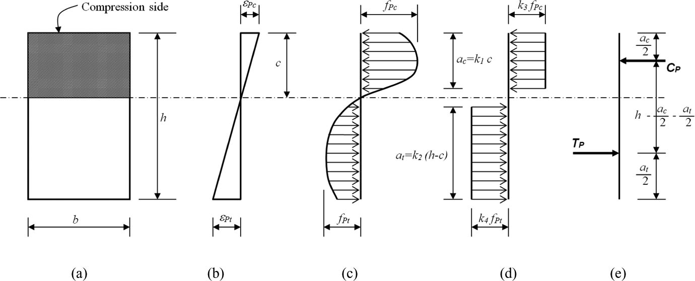
Stress and strain distribution across unreinforced beam depth, (a) beam cross section, (b) strains, (c) actual stress blocks, (d) assumed equivalent rectangular stress blocks, and (e) resultant forces.
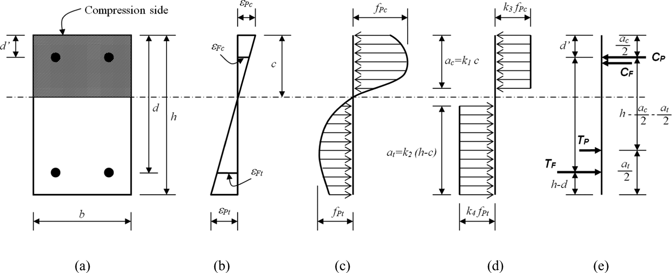
Stress and strain distribution across reinforced thermoplastic beam depth, (a) beam cross section, (b) strains, (c) actual stress blocks of thermoplastic material, (d) assumed equivalent rectangular stress blocks of thermoplastic material, and (e) resultant forces including that of FRP reinforcement. FRP: fiber-reinforced plastic.
The stress distribution in the thermoplastic is assumed to be parabolic both in compression and tension. The equivalent rectangular stress distributions are proposed for thermoplastic section. The distance from top fiber to neutral axis is defined as c. The ultimate strength of thermoplastic under tension is fPt and the ultimate strength of thermoplastic under compression is fPc. The depths of the assumed rectangular stress blocks in tension and in compression are given as k2(h−c) and k1c, respectively. The k1
, k3
, k2
, and k4
are the coefficients dependent on the material properties of thermoplastic and to be defined by tests. The compression forces due to thermoplastic (C
P) and FRP (C
F) reinforcement are


The tensile forces due to thermoplastic (T
P) and FRP (T
F) reinforcement are


Considering the equilibrium in the section,


By considering both the compatibility and equilibrium conditions, the depth of neutral axis from the top, c should be found through iteration.
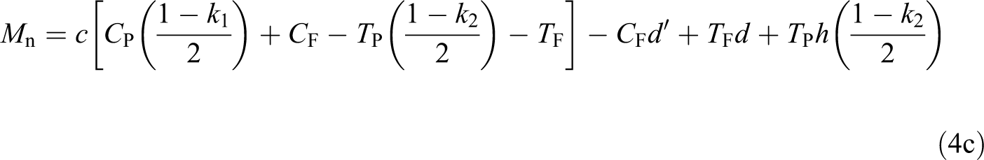
The nominal moment strength is found by multiplying all the affecting internal forces with their distances to the neutral axis as

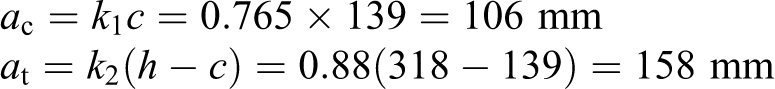
where ac
is the depth of equivalent rectangular compression stress block and at
is the depth of equivalent rectangular tension stress block as shown in Figures 1 and 2. After substituting ac
and at
in Equation 4a,

or
If the beam is made without any reinforcement and following the above notations, the equilibrium

or

The depth of neutral axis from the top fiber, c also be found through iteration while considering compatibility and equilibrium conditions.
The nominal moment strength of a section without any reinforcement can simply be found by ignoring all the resultant forces borne by the reinforcement in equation (4c) to become as

or if C
P and T
P from equations (1b) and (2b) are substituted in equation (6a),

If the stress strain distributions are found similar in shape for tension and compression after compatibility condition is applied, then k3 can be assumed equal to k4 . Also, k1 and k2 that are used to define the depth of equivalent stress block depend on the value of ultimate stress values.
The nominal moment strength of a beam without reinforcement is found by multiplying C
P or T
P with moment arm,

Substituting T
P in equation (2b) and a
c and a
t from Figure 1,


Although equation (7c) is seemingly difficult, using tables or graphical presentations can provide the needed aid to the practicing engineering while designing such members. In the following sections, using data from laboratory tests the material properties of thermoplastic and FRP reinforcement are provided. After that, using the guidelines from reinforced concrete design, 14,15 the coefficients for stress distributions are defined. Finally, beam test data and computations outlined here are given for comparisons.
Experimental verification
To verify the proposed rectangular stress distribution for thermoplastic material procedure, tests are carried out regarding thermoplastic and FRP materials themselves and also full-scale beam tests.
Tested material properties of thermoplastic
The beams used in this study are recycled thermoplastic material as seen in Figure 3. 16 To evaluate the mechanical properties of thermoplastic material, several small pieces are cut from the thermoplastic beam to be used in compression and tension tests as shown in Figures 4 and 5, respectively.
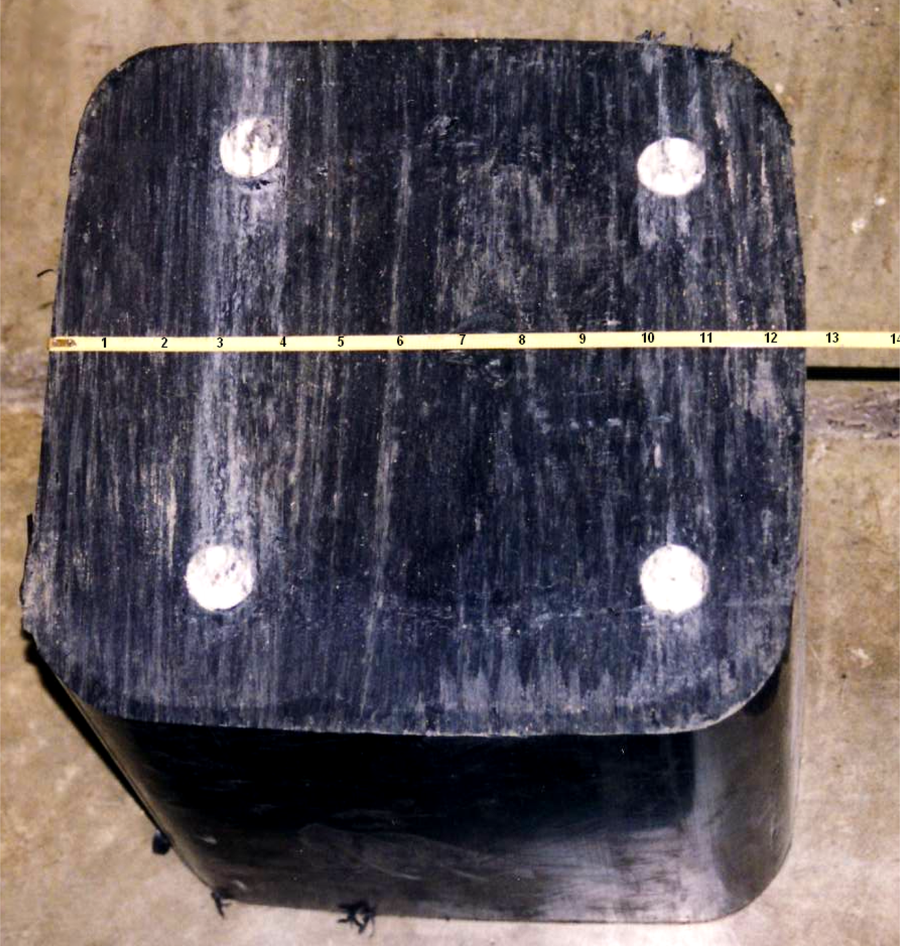
Cut section of a FRP-reinforced thermoplastic beam. FRP: fiber-reinforced plastic.
Generally, the plastic material does not fail in compression by a shattering fracture (Figure 4), the compressive stress rises steadily in the process, without any well-defined fracture occurring. The samples have shown large deformations under tension eventually failing by breaking into two parts as shown in Figure 5.
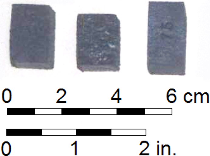
Thermoplastic compression of test specimens.
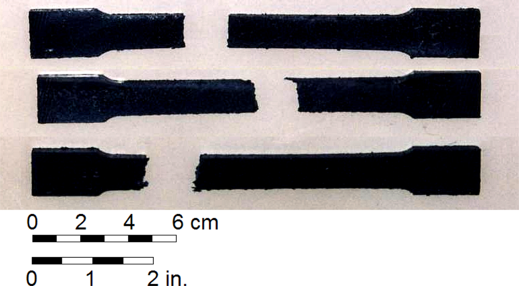
Thermoplastic tension of test specimens.
The beam is composed of recycled thermoplastic. Across the cross section, the material shows different properties, such as dense outer layer encloses lightweight material. The properties of lightweight material inside also differ across the section. Therefore, the tension and compression properties of the section are investigated by sampling small samples across the section. To simplify the design process, the overall averaged thermoplastic material stress–strain relations are used. For high accuracy in prediction of ultimate strength and behavior of beam under bending, Coskun 16 used a more detailed approach. In Coskun’s work, the moment-curvature analysis along with the material properties of many small areas of section is used to determine the load-deflection behavior. Although this approach can be touted as better to predict the behavior, for the practicing engineer a simplified approach is preferred. In the simplified approach, first the material properties should be general yet represent enough detail the variability and calculations should comprise minimum steps. Therefore, at each strain level in compression and tension, the stresses at overall cross section are averaged as shown in Figure 6. The figure shows that the thermoplastic material is stronger in compression than in tension. The tensile strength of thermoplastic is about 50% of the compressive strength. Thus, tensile strength of thermoplastic is also taken into consideration in the flexural analysis.
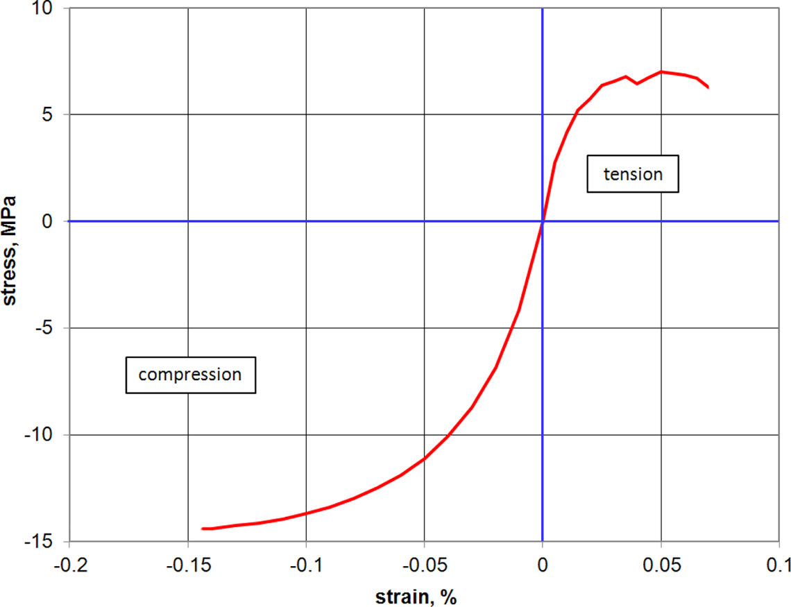
Thermoplastic stress–strain relation.
FRP reinforcement compressive and tensile properties
The uniaxial stress–strain relations of FRP rebars are also established through tension and compression tests. The stress–strain relationships under compression and tension are linear. From the experimentally generated stress–strain relations of FRP rebar compression specimens, the average values of the compressive Young’s modulus, E c, is found to be 16 GPa. The average value of the tensile Young’s modulus is found to be Et = 33 GPa.
Beam tests and verification
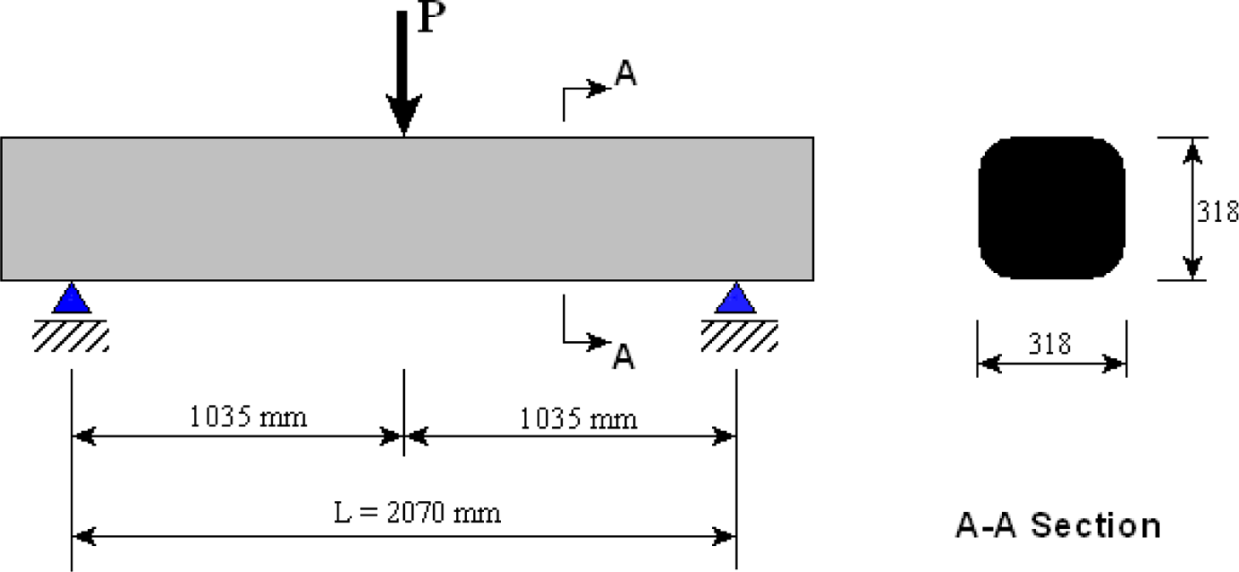
The nominal cross-sectional dimensions of tested beams are 318 × 318 mm2. The FRP-reinforced thermoplastic beam has the same length and overall cross-sectional dimensions as those of the thermoplastic beam without FRP rebars but is reinforced with four 25 mm diameter at each corner with 50 mm cover as shown in Figure 3. The beams have no stirrup or vertical reinforcement.
A load-reaction frame is used to test the thermoplastic beams. The clear spans of thermoplastic beam specimens are 2070 mm. The beam ends are simply supported, and the beam is loaded at midspan as shown in Figures 7 and 8. The midspan deflections are measured. Load is applied incrementally until the beam maximum load-carrying capacity is reached. The experimental load–midspan deflection results for both beams are given in Figure 9.
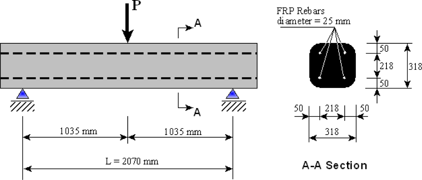
FRP-reinforced thermoplastic beam test configuration. FRP: fiber-reinforced plastic.
Thermoplastic beam test configuration.
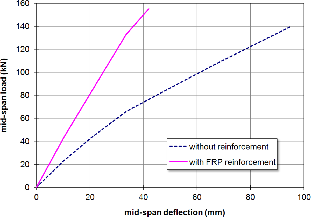
Bending test results of thermoplastic beams.
The beam without reinforcement fractured and collapsed suddenly showing brittle failure. However, the FRP-reinforced beam was still held together by rebars even after the thermoplastic section had fractured at midspan as shown in Figure 10. The slippage of rebars in the thermoplastic beam at high loads played a significant role in the beam load-carrying capacity. When FRP-reinforced beam approached the maximum load, the tension rebars had slipped by about 5 mm. Shortly after the FRP rebars slippage, the beam fractured and failed.
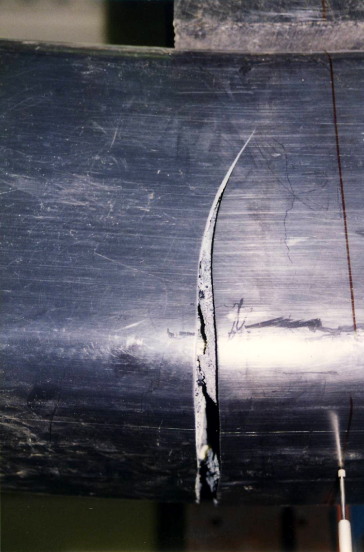
Failed FRP-reinforced thermoplastic beam after bending test. FRP: fiber-reinforced plastic.
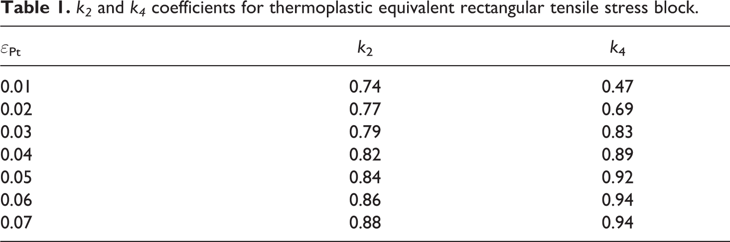
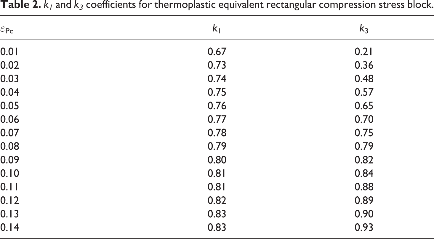
In the following section, the proposed rectangular stress distributions are used to predict the experimental behavior of the thermoplastic beams. The values of k i coefficients are given in Tables 1 and 2. The material properties are as follows: the thermoplastic tensile strength fPt = 7 N/mm2; the thermoplastic compression strength fPc = 14.4 N/mm2; the FRP tensile bond strength fFt = 200 N/mm2; the FRP compression bond strength fFc = 200 N/mm2. The geometry of the both beams (FRP-reinforced and no-reinforcement thermoplastic) are: the width b = 318 mm; the height h = 318 mm. The FRP geometric properties are: the top reinforcement area AFc = 2 × 507 = 1014 mm2; the bottom reinforcement area AFt = 2 × 507 = 1014 mm2; the distance of top reinforcement from top surface d′ = 64 mm; and the distance of bottom reinforcement from the top surface d = 254 mm.
k2 and k4 coefficients for thermoplastic equivalent rectangular tensile stress block.
k1 and k3 coefficients for thermoplastic equivalent rectangular compression stress block.
The examples related to tested thermoplastic beams are given using the formulas and the proposed values. First, the thermoplastic beam reinforced without rebar is presented. The neutral axis depth from the top surface, c is assumed at a half depth of cross section in the first iteration step.
If the strain at the farthest tension fiber ε
Pt is taken as 0.07 and considering the strain compatibility of section, the strain at the farthest compression fiber ε
Pc becomes 0.07. Hence, the stress at the farthest compression fiber found as f
Pc = 12.5 N/mm2 from Figure 6. The stress block coefficients are; k1
= 0.78 and k3
= 0.75; k2
= 0.88, and k4
= 0.94.


Since the equilibrium is not satisfied, the new value for c is assumed to be 139 mm. Taking ε
Pt = 0.07 leads to ε
Pc = 0.0544, hence k1
= 0.765 and k3
= 0.672; k2
= 0.88, and k4
= 0.94 from Tables 1 and 2.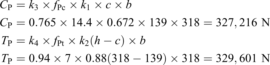
The values are very close, so the equilibrium is considered to be satisfied. The depths of compression and tension equivalent rectangular stress blocks are
The nominal moment capacity is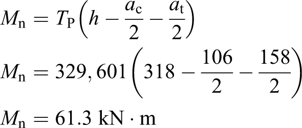
The corresponding concentrated load value for a simply supported and loaded at beam midspan is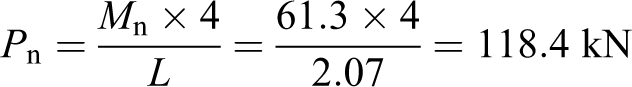
The observed load at collapse of the thermoplastic beam without reinforcement is 139.7 kN which is about 18% greater than the above calculated value. The possible reason for this difference is the uncertainties in the material properties. Especially, the tensile stresses are taken as averaged across the section, therefore not representing the true nonhomogeneous nature of this specific thermoplastic material. Considering the brittle failure of the unreinforced thermoplastic beam, the underestimated moment capacity in design may be preferable.
Second, the thermoplastic beam reinforced with FRP rebars is presented. The failure mode of this type of beam can be quite complicated as mentioned previously. Here, the beam is supposed to fail by the bond failure of tensile FRP rebars. So, the calculations start by the supposing ε
Ft and then iterating the neutral axis depth following the compatibility and equilibrium conditions.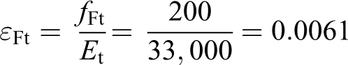
The neutral axis depth from the top surface, c is assumed at a half depth of cross section in the first iteration step.
The strain in the FRP in compression is, ε Fc = 0.0061; the strain in the thermoplastic in extreme compression fiber is, ε Pc = 0.01; and the strain in the thermoplastic in extreme tension fiber is, εPt = 0.0061. The ki values are taken as accordingly.
The resultant compression and tension forces in thermoplastic and FRP are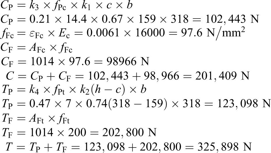
Since the equilibrium is not satisfied, the new value for c is assumed to be 179 mm. The strain in the FRP in compression is, ε Fc = 0.009; the strain in the thermoplastic in extreme compression fiber is, ε Pc = 0.015; and the strain in the thermoplastic in extreme tension fiber is, ε Pt = 0.011. The ki values are taken as accordingly from Tables 1 and 2.
The resultant compression and tension forces in thermoplastic and FRP are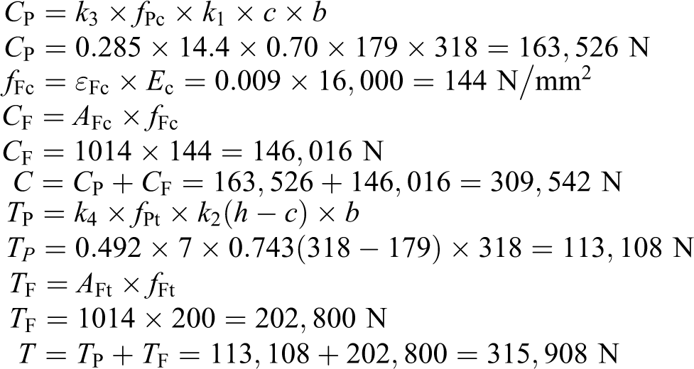
Since the values are very close, the equilibrium is considered to be satisfied. The depths of compression and tension equivalent rectangular stress blocks are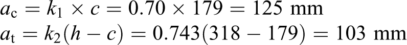
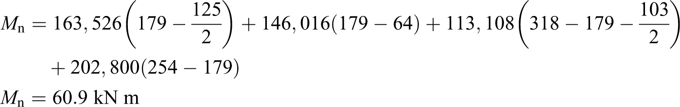
The nominal moment capacity is
The corresponding concentrated load value for a simply supported and loaded at midspan beam is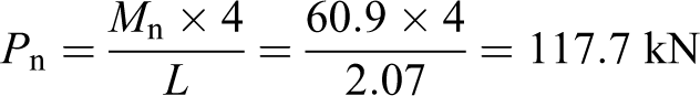
The observed load is 155.7 kN, which is about 32% higher than the above calculated value. The main reason for this can be again the uncertainties in defining the thermoplastic material properties. The capacity of reinforced beam is found about 12% higher than that of unreinforced beam experimentally. As said previously, the unreinforced thermoplastic beam collapses suddenly without any warning; however, the reinforced beam although collapse similarly held together with the FRP reinforcement. Considering these results, it should be preferable to use reinforcement in the thermoplastic beams.
Conclusions
In this study, the thermoplastic beams with and without FRP reinforcement are investigated. The investigation included finding the material properties of thermoplastic and FRP through tests as well as the experimental and analytical study of flexural behavior the beams. According to thermoplastic material tests, the thermoplastic material exhibits a relatively brittle type of tensile failure. The response of the thermoplastics to compression yields to its flattening under loading. The thermoplastic tensile ultimate strength is also about 50% lower than the compressive strength. The material properties of FRP are also determined by tests. The normal tensile and compression stress–strain curves of the FRP rebar are linear until fracture occurs.
The experimental material properties data is provided for the USD analysis of thermoplastic flexural members. The equivalent rectangular stress distribution model is used to predict the uniaxial behavior of thermoplastic material. The model well anticipates the flexural capacity of thermoplastic beam without reinforcement. Due to the debonding of the FRP rebars from the thermoplastic material in the experiment at high loads, the actual ultimate load-carrying capacity of the FRP-reinforced thermoplastic beam is found to be more than that predicted theoretically. Although the predicted behavior did not match the test results for FRP reinforced thermoplastic beam, the tests may provide an important hint in using these members in structures. As seen in thermoplastic beam without FRP reinforcement, the failure is sudden and results in total collapse of the beam. The reinforcement, however, allows large strains and therefore greater deflections without taking any more loads before total collapse. The pseudo ductility of FRP-reinforced beams are provided by slippage between the FRP rebars and thermoplastic matrix.
This study indicates that thermoplastic beams with and without FRP reinforcement possess a good potential for both civil and noncivil engineering applications. The analysis to determine the flexural capacity may be applicable to other types of thermoplastic beams. The debonding between the thermoplastic material and FRP bars needs more investigation. More importantly with regard to this study is that the coefficients in the USD equations should also be modified by doing more experiments in future research.
Footnotes
Acknowledgments
The author is indebted Prof Dr Zia Razzaq from Old Dominion University, USA, for his invaluable comments. The experimental part of this study is conducted on the thermoplastic beams called Seatimber which were donated by Trelleborg AB formerly known as Seaward International, Inc, Virginia, USA.
Declaration of Conflicting Interests
The author(s) declared no potential conflicts of interest with respect to the research, authorship, and/or publication of this article.
Funding
The author(s) received no financial support for the research, authorship, and/or publication of this article.