
Abstract
In this article, a commercial grade of polypropylene (PP) was reinforced with short poly(ethylene terephthalate) (PET) fibres up to 30 wt%. In order to have a reactive interface, two different compatibilizers, glycidyl methacrylate (GMA)-grafted PP and maleic anhydride (MA)-grafted PP, were used. To choose an optimized fibre length for the PET fibre in PP/PET composites, critical PET fibre length was evaluated applying stress analysis and Von Mises yield criterion. PP/PET fibre pre-pegs were prepared by melt impregnation technique using an internal mixer followed by the compression moulding. Tensile and flexural properties were investigated. Morphological studies were carried out by scanning electron microscopy technique. It was observed that the addition of PET fibres enhanced flexural modulus compared with that of pure PP, which was higher for GMA-modified composites. The tensile modulus results also showed enhancement by the addition of PET fibres. However, the tensile modulus of unmodified specimens versus fibre load was little greater than that of unmodified samples up to 15 wt% of fibres due to higher crystallinity. The flexural strength results of modified composites versus fibre wt% also showed enhancement that was higher for those of GMA-modified ones. The fibre to matrix bonding was better in the presence of GMA than that of MA, as revealed by scanning electron micrographs of tensile fracture surfaces. Halpin–Tsai, Pan and Cox–Krenchel equations were applied to predict the tensile modulus of random PET fibre-reinforced PP composites, among which the Pan’s model had the best prediction. To evaluate relative reinforcement at different fibre loads, fibre efficiency factor was calculated for GMA-modified composites.
Introduction
Fibres have frequently been used to enhance the strength and stiffness of polymers. 1 Ease of manufacturing, good mechanical properties and isotropic behaviour are some of the distinctive benefits of short fibre composites. 2 Short fibre-reinforced thermoplastics are becoming more admired in many applications over other types of fibre–matrix composites. In these composites, the toughness of thermoplastic polymers with the stiffness and strength of reinforcing fibres come together. In addition, these composites can easily be processed by common techniques such as injection and compression moulding. 3,4 Polypropylene (PP) is one of the most applicable thermoplastics in short fibre composites particularly owing to good mechanical properties, being economical, the ease of processing and environmental security. 3,5 Among various fibres used to reinforce PP, glass fibres are the most common. 6 However, present environmental troubles caused by the concentration of PP/glass fibre composite products in waste areas, their partial combustibility, their fragility and the increasing demand for techniques of recycling made a notable reduction in the growth rate of glass fibre-reinforced composite projects. 7 In addition, it is well-known that synthetic polymeric textile fibres like PET and nylon fibres are becoming very popular in PP reinforcing. Besides, in these composites, fibres are not brittle and the composite can be easily processed and also be recycled. 3 –6,8 –12 In the present work, PET fibres were used to reinforce PP matrix since it offers different advantages over other fibres: (a) availability; (b) low density; (c) relatively good mechanical properties and (d) recyclability. 6,13 As a result, PP/PET composites offer some important characteristics like ease of processing, being inexpensive and recyclability. One main problem in PP/PET composites is that they have a weak interface due to the different types of chemical structure, which reduces the strength of these composites. In order to enhance the interactions at the PP/PET composites interface, chemical modification of the matrix has usually been undertaken. Different coupling agents have been used to modify the matrix in the last few years; the most well-known is maleic anhydride (MA). 5,6,8,14 Another important coupling agent, very common in PP/PET alloys, is glycidyl methacrylate (GMA). 15 –19 GMA has not been used before in PP/PET composites and owing to its capability of being reactive towards both hydroxyl and carboxyl end groups of PET chains, it could be very efficient in making strong bonds at the interface of PET fibre-reinforced PP composites. Additionally, different from MA, GMA does not generate side product of water in the course of its chemical reactions by the PET chain end groups. Figure 1 shows GMA reaction with the end groups of PET fibre chain. Our earlier study has proved PET fibres to be an effective reinforcement in raising thermal stability and impact resistance of PP matrix. 20 Transcrystalline layer (TC) was also investigated in PP/PET composites, which raised the amount of crystallinity and stiffness at the unmodified fibre–matrix interface. 6,20,21 To further study the crystallinity and the TC, differential scanning calorimetry (DSC) was applied. Previous work also approved the role of GMA modifier in enhancing the tensile strength of PP/PET fibre composites.
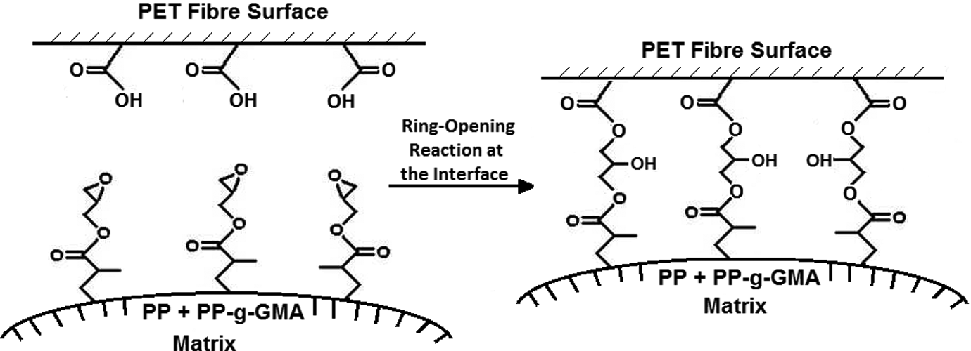
Schematic representation of reaction between PET end groups and GMA moieties grafted onto the PP backbone.
In this study, fibre critical length (l c) calculation based on stress analysis and Von Mises yield criterion is presented to select an optimized fibre length in PP/PET composites. Pre-pegs of PP/PET fibre composites were prepared with and without compatibilizers of GMA-grafted PP (PP-g-GMA) and MA-grafted PP (PP-g-MA). Tensile and flexural properties were measured. Scanning electron microscopy (SEM) technique was employed to study fibre–matrix interactions at the composite tensile fracture surfaces. Furthermore, in this article three micromechanics models were applied to predict the stiffness of PP/short PET fibre composites. Moreover, fibre efficiency factor was calculated for GMA-modified composites to compare relative reinforcement at different fibre contents.
Experimental and procedures
Materials
PP with a melt flow index (MFI) of 3–5 g/10min (at 190°C, 2.16 kg) and density of 0.935 g/cm3 was used as the matrix in powder form. This product was supplied by Petrochemical Co Industries, Tehran, Iran, with the trade name of C30S. PET fibre (a commercial grade of textile polyester, fully oriented yarn ) with a diameter of 11.2 µm and density of 1.38 g/cm3 was supplied by Polyacrylic Corporation, Isfahan, Iran. The PET fibres were chopped to the average length of 4 mm, higher than the calculated l c of the PET fibre. In order to examine the PET fibre tensile properties, tensile test for a single PET fibre was conducted, according to ASTM D3822. For this test, 25 mm of a single PET fibre was cut and placed between the two gripes of the tensile testing machine (Zwick model). Then the test was performed at a crosshead speed of 15 mm/min. This test was repeated 30 times for different single PET fibre specimens. For the fibre tensile test, fibre tensile strength, tensile modulus and yield stress were measured as 550 MPa, 12,000 MPa and 500 MPa, respectively. PP-g-GMA was prepared by the melt-grafting technique in our laboratory, consistent with Parcella and Chionna. 15 Accordingly, styrene-assisted free radical grafting of GMA onto the PP backbone was carried out in a Brabender internal mixer at 190°C and at a rotor speed of 60 r/min. For this, GMA, styrene and initiator were premixed with PP der at room temperature. Then the mixture was fed into the mixer under nitrogen flux for 5 min. Styrene was used as a comonomer in the GMA-grafting process to reduce PP chain scission and therefore enhance the grafting efficiency of GMA; 9 Phr (parts per hundred resin) GMA, styrene/GMA molar ratio of 1 and 0.5 Phr dicumyl peroxide as an initiator were used.
PP-g-MA, OREVAC® CA 100, supplied by Arkema Co., (Arkema Co) was applied as another modifier (MFI of 150–200 g/10 min at 230°C and 2.16 kg).
Composite preparation
To remove the probable trapped water, the PET fibres were placed in an oven at 100°C for 4 h. Selection of the operational temperature of pre-peg preparation was mainly based on the information obtained by DSC of the PET fibres. Figure 2 shows the DSC diagram of the PET fibres heated to 300°C and then cooled to the temperature environment. The DSC test was performed at a heating rate of 10°C/min under a nitrogen atmosphere using the DSC 200F3, NETZSCH model. The mixing temperature of PP/PET was selected to be 180°C, which is higher than the melting temperature of PP (150–160°C) and lower than the temperatures in which crystallization and thereafter melting of PET fibres begin to happen (235–260°C). At higher temperatures, the degree of fibre orientation will decrease and fibre physical and mechanical properties will be deteriorated.
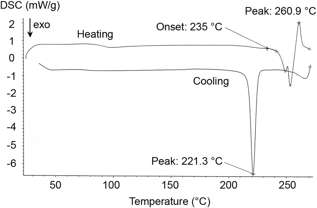
Differential scanning calorimetry thermogram of PET fibre with the heating and cooling rate of 10°C/min.
PP/PET pre-pegs were prepared by adding the PET fibres to the melted PP in a Brabender internal mixer at a temperature of 180°C and 60 r/min rotor speed in both the presence and absence of compatibilizers. Three different kinds of PP/PET pre-pegs, WO (without modifier), WMA (with PP-g-MA) and WG (with PP-g-GMA), at various fibre amounts of 5, 10, 15, 20 and 30 wt%, were mixed up. The amount of used modifier was 10 Phr in every mixing run. The impregnation was carried out for 10 min to make sure appropriate wetting of fibres with the PP matrix. Then the hot press method at 100 bar and 180°C was applied to mould the PP/PET fibre pre-pegs.
Tensile and flexural properties
Tensile and flexural properties of the composites were found by a Testometric Universal testing apparatus (Rochdale, UK). To carry out the tensile test, composite sheets with a thickness of 3.2 ± 0.4 mm for each fibre load composite were prepared by compression moulding technique. Then dumbbell-shaped specimens were prepared using a mould cutter (an overall dumbbell length of 115 mm, a narrow section width of 6 mm and a gauge length of 25 mm, according to ASTM D638). The crosshead speed for the tensile test was 5 mm/min. Flexural tests were conducted as ASTM D790 at a crosshead speed of 4.8 mm/min and the specimen dimensions of 127 × 13 × 3 mm3. Four specimens per each fibre load composite were used in tensile or flexural test.
Morphological study
SEM technique, model AIS2100 microscope, Seron Technology Corporation (Gyeonggi-do, Korea), was employed to investigate the fracture surfaces of specimens used in the tensile tests.
Critical fibre length calculation
In short fibre composites, fibre length plays a crucial role in final mechanical properties. For fibre lengths greater than critical fibre length (l
c) the maximum fibre stress may reach the final fibre strength over much of its length, and therefore fibres use much of their potential to enhance mechanical properties.
22
–24
For a known fibre diameter and fibre–matrix interfacial circumstance, a critical fibre length l
c is obtained from equation (1).

where d
f and σ
fu are fibre diameter and fibre tensile strength, respectively, and τ is the interfacial shear stress. Assuming a perfect bonding between the fibre and the matrix, the interfacial shear strength becomes the yield shear strength of the polymer matrix (τ
y).
23
τ
y was calculated based on the stress analysis and Von Mises yield criterion
25,26
by equation (2).

where σ
1, σ
2 and σ
3 are principal stresses. For an in plane pure shear stress element, Mohr’s circle is presented in Figure 3. By substituting the principal stresses obtained from Mohr’s circle, which are σ
1 = τ, σ
2 = −τ and σ
3 = 0, in equation (2), equation (3) that was used to calculate the τ
y for the matrix is driven: Schematic representation of pure planar shear element and its Mohr’s circle.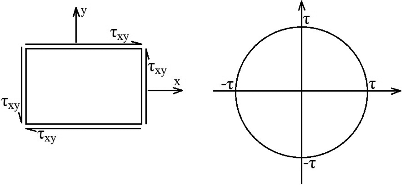

where σ yp is the yield stress of the matrix, which is 27 MPa for the PP matrix.
Composite models
There are different micromechanics models developed to evaluate the elastic modulus of short fibre-reinforced composites. Some of these models used in this work are presented.
Halpin–Tsai equation
One of the most famous micromechanics models used to predict the tensile modulus of short fibre composites is the Halpin–Tsai equation. This equation was modified by Nielsen with the purpose of using for random in plane fibre orientation composites.
1,22,24,27,28


where V
f, E
f, E
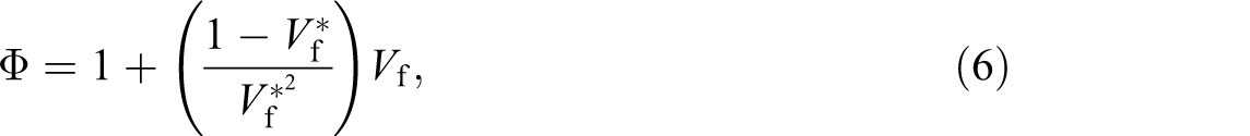
m and E are fibre volume fraction, fibre modulus, matrix modulus and composite modulus, respectively. ζ = 2(l/d) in which l and d are the reinforcement length and diameter, respectively. The factor
Cox–Krenchel equation
Another common theory utilized to model the modulus of random-in-plane short fibre composites was developed by Cox and then modified by Krenchel. For a unidirectional composite, a correction factor of η
1 must be considered in the rule of mixture to justify the length of fibre not entirely contributing to the improvement of the stiffness of the composite. That is due to the shear stress transfer between each fibre and the matrix. Nonetheless, Krenchel expanded this study to consider fibre orientation by the addition of a fibre orientation factor, η
0, into the rule of mixture as follows
1

For a random fibre composite, orientation factor is regarded as 3/8 and η
1 is around 1 for long enough fibre-reinforced composite as presented in equation (8).

Pan’s model
Another approach was developed by Pan to estimate the elastic modulus of randomly oriented fibre composites.
2
Pan started with the rule of mixture for a unidirectional composite to estimate composite modulus. He used a probability density function to indicate the fibre orientation described by a pair of angles in a spatial curvilinear coordinate. After that the fibre area fraction is connected to the fibre volume fraction via another probability function, as follows in equation (9).

where, Ω(Θ,Φ) is the probability density function in a specific (Θ,Φ), which is a pair of angles. The concluding result of Pan’s study is an equation for composite young modulus.

For a two dimensional random fibre composites, the model could be simplified and the young modulus can be expressed as equation (11).

Fibre efficiency factor
Another approach applied to estimate the short fibre composites modulus is fibre efficiency factor (K
E). Blumentritt and Cooper
29
proposed a way to determine the Young modulus of the composite in the fibre plane. Their result is presented as follows:

This technique permits different fibre loaded composites to be compared in relative efficiency of enhancing the composite young modulus.
Fibre volume fraction
The fibre volume fraction (V
f) at different fibre weight percentages (w
f) was calculated by the following equation.
30

where ρ f and ρ m are the densities of the PET fibre and PP matrix, respectively.
Results and discussion
Critical fibre length was calculated based on equation (1); l c of about 0.2 mm was obtained for PET fibre reinforcement, which is common for such thermoplastic fibres. 31 The l c selection for the fibre length is on the condition of existing complete attraction between fibre and the matrix. However, voids and defects are produced at the fibre–matrix interface inevitably. For the composites under study, the average fibre length was chosen to be greater than l c, which is essential to ensure effective stress transfer from the PP matrix to the PET fibre as composites are mechanically overloaded. On the other hand, selecting too long fibres deters proper mixing of fibre with the PP matrix by the formation of fibre entanglements in the bulk of matrix during impregnation process. These entanglements could cause stress concentration points and therefore cause failure while the stress is applied to the composite. Composite flexural modulus versus fibre wt% for WO, WMA and WG samples are presented in Figure 4. The results showed that flexural modulus increases by the enhancement of PET fibres; this increment is greater for WG composites being mainly due to stronger bonds at the fibre–matrix interface. In our earlier study, the melt mixing torque results confirmed that the formation of chemical bonds occurred at the fibre–matrix interface due to higher torque values of WG pre-pegs. At higher fibre concentrations, the flexural modulus is lower than the trend. The possibility of fibre entanglements in the composite with random fibres was amplified as the fibre concentration increased. That results in a higher stiffness in the out-of-plane direction and a following reduction of in-plane stiffness. This effect is more conspicuous in compression test than tensile test. As a result, the bending data have a higher sensitivity that can be explained according to both compressive and the extensive stresses throughout the flexural test. According to Houshyar et al., this deviation could also be due to fibre packing and insufficiently rich polymer regions, illustrating that by increasing the amount of fibres, there are areas with inadequate matrix, particularly between the fibres. This means that fibres are no longer entirely covered by the matrix at very high fibre percentages and voids are created in the composite. It has been reported that most of the composite properties are influenced by the creation of voids in the composite structure. 1
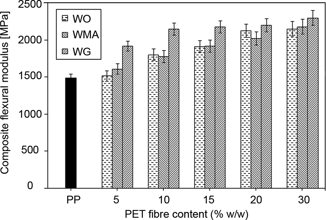
Flexural modulus vs. fibre weight fraction for WO, WMA and WG PP/PET composites.
Composite Young’s modulus at different PET fibre contents is illustrated in Figure 5 for both modified and unmodified samples. It can be seen that the Young modulus is strongly influenced by increasing the amount of fibres. At low fibre percentages like 5 or 10 fibre wt%, there is not enough fibre to control the matrix; hence, the applied stresses to the composites are not properly distributed. As a result, the Young modulus does not show an enhancement proportional to the fibre contents. It can be noticed that the Young modulus of WO samples at lower fibre fractions is a little higher than those of the modified ones due to higher crystallinity. Saujanya and Radharkrishnan stated that the presence of both PET fibre and compatibilizer reduces the segmental motion of PP that restricts the growth of crystallites and, therefore, crystallite or spherulite size becomes so small. 7 Among the modified composites, WG samples show greater young modulus due to the capability of GMA to be reactive towards both hydroxyl and carboxyl end groups of PET chains and, as a result, causing stronger interactions at the PP/PET interface. It could also be explained by lower tendency of GMA to reduce the amount of crystallinity of PP in comparison with MA as confirmed by DSC thermograms in our pervious study. 20 The increase in tensile modulus in PP/PET fibre composites can be due to: (a) reinforcing effect of PET fibres; (b) higher crystallinity of PET fibre and (c) TC, a distinctive morphology which is mainly due to columnar growth of PP crystallites on the PET fibre surface. 6,21 In our previous work, 20 it was shown that there was no TC around the fibre in modified samples; however, around some fibres in WO specimen several TC regions were found, which increase the amount of crystallinity in unmodified composites. This contributes to lower crystalline values of the modified composites at low fibre percentages. It can be seen that at higher fibre contents, the WG young modulus exceeds the Young modulus of other composite types.
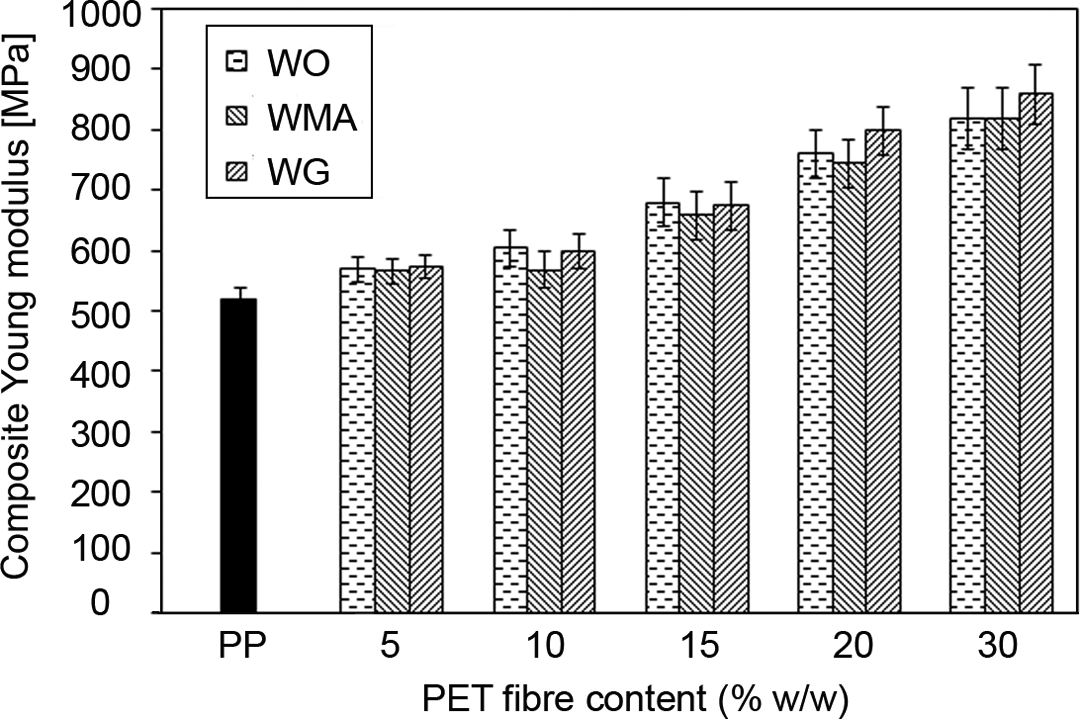
Tensile modulus of WO, WMA and WG PP/PET composites versus fibre wt%.
The flexural strength values of PP/PET fibre composites versus fibre concentration are shown in Figure 6. It is confirmed that the WO sample flexural strengths decrease by adding PET fibres due to weak interaction at the fibre–matrix interface; however, the flexural strength of the modified samples showed enhancements up to 10 wt% of fibre and then starts to decrease. That is mainly owing to the fact that the reinforcement caused by the fibres leads to stress transfer from the matrix to the fibres by exerting stronger interface. Flexural strength values of the WG samples are greater than those of WMA composite apparently due to superior interaction at the fibre–matrix interface. The flexural strength growth was higher for WG composites (≈10 Mpa). Obviously, at higher fibre percentages like 20 or 30, short fibres lose their reinforcing effect, which is due to the fact that there is no enough matrix to surround all the reinforcements; further, voids and flaws are produced in the composites. 1 Scanning electron micrographs of tensile fractured surfaces of PP/PET composites are presented in Figure 7. The WO fracture surface (Figure 7(a)) explains that there is hardly any adhesion at the fibre–matrix interface since most of the fibres are pulled out from the polymer matrix without any PP matrix trace and fibres are cleanly scattered on the fracture surface. Figure 7(c) reveals that there is a good interaction at the fibre–matrix interface of the WG sample as a consequence of having matrix trace on the PET fibres. It is obvious that in the WG composite, matrix got its yield point and the amount of pulled out fibres is decreased when compared with the WO fracture surface, which discloses good entrapment of fibres in the PP matrix in the presence of GMA modifier. Figure 7(b) and (c) shows that the adhesion of fibre to the matrix in WG samples is stronger than that of MA modified ones. Showing cleaner fibre surfaces in their tensile fracture surface, WMA demonstrates weaker interactions between fibre and the matrix than those of WG specimen.
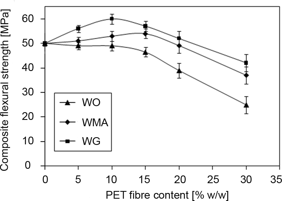
Flexural strengths of WO, WMA and WG PP/PET composites versus fibre wt%.
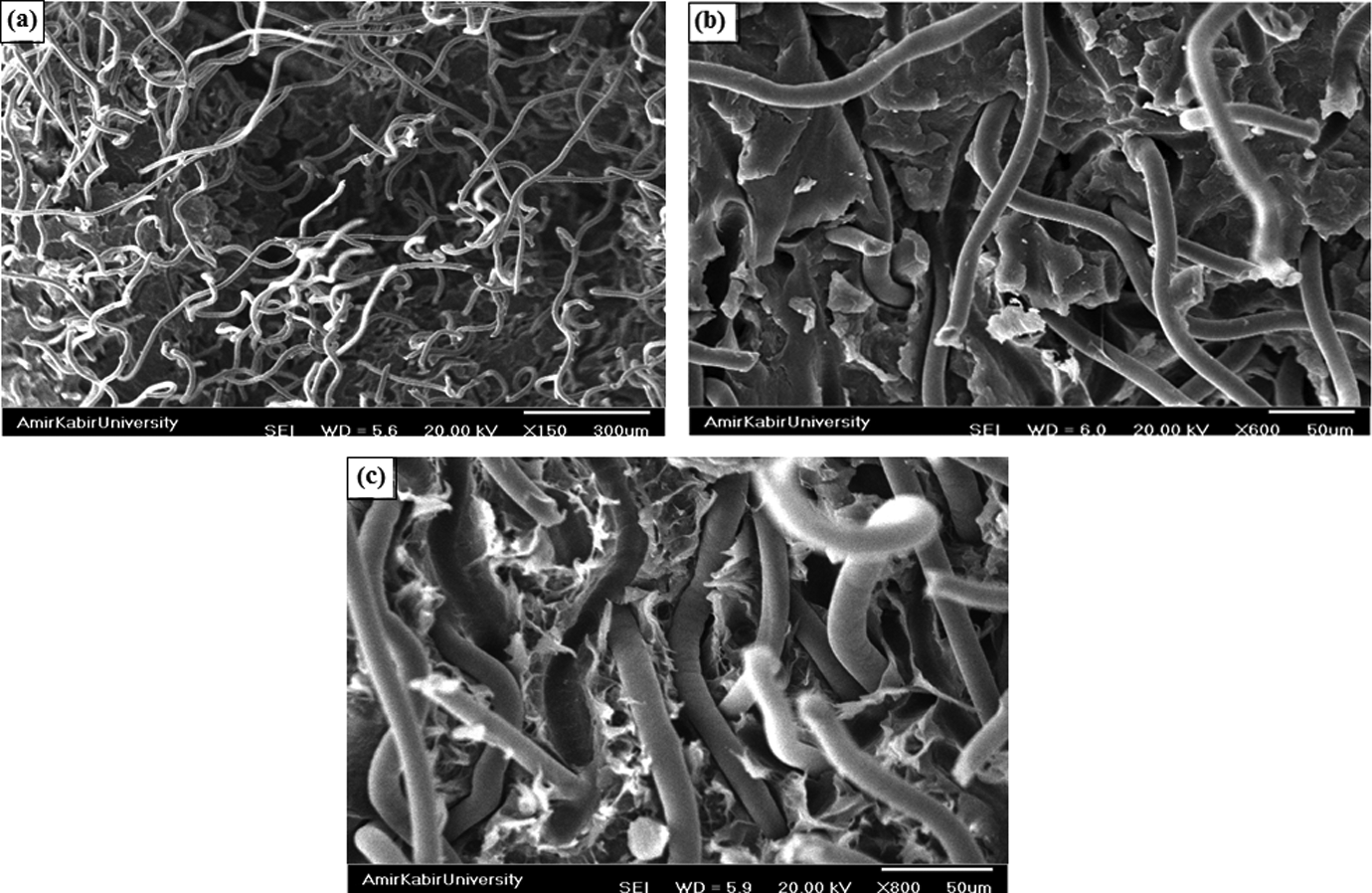
Scanning electron micrographs of tensile fracture surfaces of 15wt% fibre composite for (a) WO: 150×, (b) WMA: 600× and (c) WG: 800×.
Experimental WG composite Young’s modulus data and calculated ones obtained through equations (4), (8) and (11) are listed in Table 1. The predicted results showed that Pan’s equation has the best prediction of composite young modulus over the rest of the models and theoretical tensile modulus by Pan’s equation almost showed a good agreement with experimental values up to 10 wt% of fibres; however, the stiffness of these composites was overestimated by this equation. In Pan’s model, it is assumed that the composites consist of identical fibres with uniform properties, distributed uniformly along the composite length, act elastically and long enough that the fibre length effect can be overlooked. All these account for some of the deviation sources of Pan’s model from experimental results. 2 The deviation was higher for the Cox–Krenchel equation than that of Pan’s model. It can be concluded from Table 1 that the Halpin–Tsai model does not give a good prediction of modulus for PP/PET composites; the model overpredicts the experimental modulus. This is due to the Halpin–Tsai equation’s nature. 1 The deviation can also be explained according to the fibre packing problem, out-of-plane or bent fibres, void content and overlooking of the fibre length distribution. Using equation (12), the following fibre efficiency factors for the WG type composites are obtained as shown in Table 2.
Experimental and theoretical tensile moduli for different fibre concentrations.
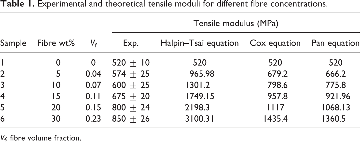
V f: fibre volume fraction.
Fibre efficiency factors (K E) for GMA-modified PP/PET composites at different fibre loads.
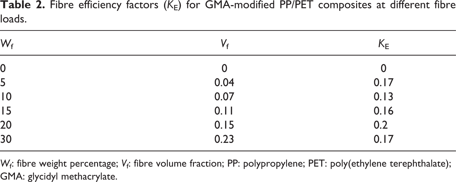
W f: fibre weight percentage; V f: fibre volume fraction; PP: polypropylene; PET: poly(ethylene terephthalate); GMA: glycidyl methacrylate.
It is clear that the fibre efficiency factor ranges from 0.04 to 0.23. This method clarifies if relative reinforcement happens at different fibre loads by comparing the calculated K E of a particular fibre concentration with that of the previous fibre content. According to this method, the composites with fibre weight percentages of 5, 15 and 20 have relatively better reinforcement effects of tensile modulus in comparison with other fibre percentages.
Conclusions
In this study, it was confirmed that PET fibres influenced tensile and flexural properties of PP. GMA was found to be an effective coupling agent. l c of about 0.2 mm was obtained for used PET fibre. Flexural modulus of GMA-modified composites had more growth over other types of specimens. The tensile modulus increased by the addition of PET fibres; however, this increment was a bit greater for WOs due to higher crystallinity at low fibre contents. The WG composite flexural strengths showed more enhancement than the other samples due to stronger role of GMA modifier in the formation of bond between fibre and the matrix. The scanning electron micrographs also confirmed the stronger interactions at the fibre–matrix interface of WG specimen. Pan’s equation had a better prediction of experimental data of tensile modulus in comparison with other models. K E calculation compared the relative reinforcement at various fibre percentages.
Footnotes
Funding
This research received no specific grant from any funding agency in the public, commercial or not-for-profit sectors.