
Abstract
The ultrasonic spot welding of fiber-reinforced thermoplastic laminates received a wide interest from researchers mainly in the fields of aerospace and automotive industries. This study investigated a new technique for focusing the ultrasonic vibration energy at the desired spot between two mating thermoplastic composite laminates. In this investigated method, no additional energy directing protrusions between the mating laminates were required to focus the vibration energy. It was found that by welding the laminates amid an ultrasonic horn and an anvil in which the prior had a larger contact surface with the laminate as the latter, it was possible to generate a localized friction heating. In the initial phase of the welding, the friction heating softened the interfacial layers and thus caused the focusing of the majority of the cyclic ultrasonic strain energy in the weld spot center. The assumption for the presence of the friction and its influence on the heat generation was investigated by means of finite element method (FEM) mechanical dynamic analysis. Microscopic analysis of the weld spot eventually delivered the proof for the melt initiation by friction at a ring around the weld spot and subsequent spot growth by viscoelastic heating.
Keywords
Introduction
The fiber-reinforced composites with thermoplastic matrix provide noticeable advantages in terms of efficient processing techniques over their thermoset counterparts. On one hand, the fiber-reinforced thermoplastic laminates may be shaped by thermoforming and on the other hand they may be joined by means of fusion bonding. Well-established fusion bonding techniques for thermoplastic composites include ultrasonic welding, induction welding, friction-stir welding, and laser welding, of which the ultrasonic welding has been found according to some researchers to be the most effective for spot welding of thin-walled composite structures. 1,2
In the ultrasonic welding of polymers in general and polymeric composites specifically, longitudinal mechanical vibrations with a frequency above the audible spectrum (usually between 20 kHz and 45 kHz) accompanied with a static force are applied through a metallic horn perpendicular on the outer surface of one of the mating parts to be joined. The vibrations cause intensive intermolecular and boundary friction heating at and around the joint interface, which in turn heats up locally and rapidly until a sufficient temperature is reached for the polymers to flow and diffuse. 3 At this point, the vibrations are stopped and the healing of the joint takes place under the pure static pressure applied through the horn. In practice, to focus the vibration energy of the ultrasonic at a desired interfacial location, energy directors are introduced there. Due to their geometry or material properties, these energy directors possess a stiffness less than the stiffness of the preceding layers. Therefore, the majority of the applied cyclic strain energy focuses at these energy directors, and thus heat up, soften/melt, and flow preferably. Ultrasonic welding in general is limited to parts with a size of approximately 230 mm in width and 300 mm in length. 3 To weld larger parts, either several ultrasonic welders should be implemented at once or the parts may be welded by the spot welding approach; a number of spot welds are applied on separate locations of the joined pair either by moving the parts under a stationary ultrasonic welder or by moving the welder to the weld spot location.
Benatar and Gutowski 4 investigated the possibility for the ultrasonic welding of fiber-reinforced Polyetheretherketon (PEEK) laminates through triangular energy directors. The energy directors were molded on one of the laminate pairs prior to welding. Zhang et al. 5 implemented an FEM model to analyze the heating mechanism of rectangular energy directors. They have concluded that in case of using rectangular energy directors, the heating initiates by friction at the outer edges of the contact interface and after softening of the matrix viscoelastic heating dominates. Ageorges et al., 1 in their review of advances of fusion bonding techniques, have identified that the absence of the energy directors can make the process troublesome. They, however, have reported that it might be difficult to introduce the energy directors on sheet components. Creating the energy directors requires subsequent molding stages which make the process inefficient. To overcome this limitation, Villegas 6 and Zhao et al. 7 have introduced an ultrasonic spot welding method in which a thin film of pure matrix is placed between the thermoplastic laminates as an energy director at the required spot. The pure thermoplastic film melts preferably and provides sufficient matrix at the joint. An ultrasonic spot welding method for fiber-reinforced thermoplastic laminates has been investigated at the BMW Group. 8,9 In this approach, an ultrasonic horn with a pin end has been used. The pin end of the horn plunges into the laminates breaks the continuous fibers, and forces the softened/melted matrix along with the broken fibers into the weld interface. Thus, when solidified, a short fiber-reinforced weld spot is created and a hole is left behind as a surface marking.
In cases where it is required to perform the ultrasonic spot welding with a high level of automation on relative large structural parts made of fiber-reinforced thermoplastics, it is sometimes impractical to insert the energy directing elements in the form of pure matrix films or mold additional energy directors. In cases where visual quality is of importance, the pin spot welding method proves inadequate. A new ultrasonic spot welding method with more flexibility for automation is essential. Therefore, in the frame of this research work, an ultrasonic spot welding method is developed which eliminates the need for any additional energy directors while causing minimum or even no surface marking. This new method is called the differential ultrasonic spot welding (DUS). In this article, the mechanisms for the friction heat generation were investigated by means of three-dimensional (3-D) explicit dynamic FEM analysis and subsequent microscopic analysis of the weld spot development.
The theory of the DUS method
The proposed ultrasonic spot welding method enables the welding of thin-walled thermoplastic or thermoplastic composite parts without the need for any sort of surface asperities or additional materials as energy directors. The elimination of the energy directing elements increases the efficiency and the flexibility of the ultrasonic spot welding process. As a result, the joining process may be implemented in the automated assembling lines of large composite structures where joint strength, process stability, efficiency, and cycle times are considered as priorities.
The configuration of the DUS is illustrated schematically in Figure 1. The two laminates (the thin-walled composites) mate through flanges. The spot weld is created between a flat-end horn and a flat-end anvil. The success of the DUS process requires the anvil contact diameter Da
to be smaller than the diameter of the horn contact Dh
. The ratio between the diameters RD
should be larger than a certain process dependent ratio (
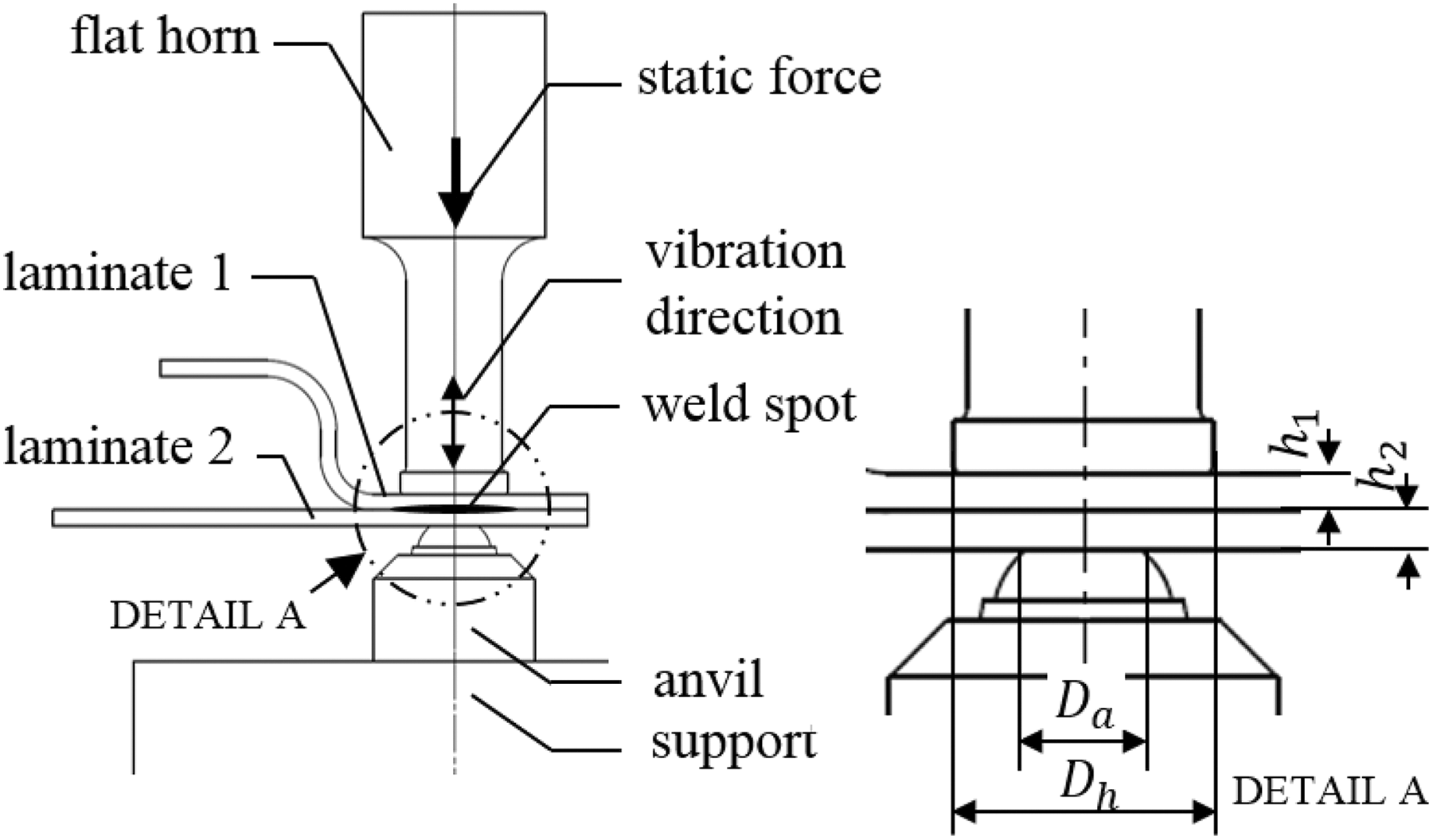
Schematic of the DUS configuration, illustrating the essential parts and dimensions.
The difference in the diameters of the horn and the anvil is assumed to cause the laminates to deform under the cyclic vibration in a way that they bend and compress simultaneously. The cyclic deformation shape of the mating laminates results in a relative movement between the contacting surfaces. Despite the slippage is infinitesimal, but due to the high vibration frequency, the adequate interfacial pressure, and the large friction coefficient, a high heat flux is generated. The name of the process “differential ultrasonic spot welding” is derived from the phenomena of the difference between the in-plane deformations of the contacting laminates, which in turn results from the difference between the horn and anvil diameters.
Directly after the application of the ultrasonic vibration, a uniform volumetric viscoelastic heat and a focused friction heat flux are generated in the spot between the horn and the anvil. At the initial phase, the generated viscoelastic heat is small. But the friction heat flux in the laminate–laminate contact interface becomes high. This focused heat flux leads to the rapid temperature increase of a thin layer from the laminates at their contact interface. And because the thermoplastic composites usually have poor heat transfer coefficients, the temperature increase occurs almost solely at the contact interface. Consequently, the interfacial layers become softer than the remaining layers and the applied cyclic strain tends to focus at those softer layers. Thus, a sharp in-thickness strain gradient situation is created. The focused strain leads to an intensive viscoelastic heat generation in the interfacial layers. As soon as the interface becomes hot enough, the surfaces start to stick against each other and the friction heating diminishes. As a conclusion, the initial friction heating causes the focusing of the applied strain energy at a thin interfacial layer and the subsequent accelerated heating and diffusion of only the desired weld spot is achieved.
The heating mechanisms
The mechanisms governing the heating of the material during the ultrasonic welding are studied in detail by several researchers. 4,5,10 –12 It may be summed up by two major heat generation mechanisms. The heating in the initial phase is dominated by the interface friction heating. It can be simplified and considered as Coulomb damping. After the interface gets hot enough, the friction gradually disappears and the heat generation is dominated by viscoelastic heating (also called intermolecular friction heating). Eventually, when most of the matrix at the interface is in the liquid phase, the pure viscous damping dissipates the vibration energy as heat. 5 , 10
If the laminates are subjected to a cyclic displacement


By substituting and solving the energy dissipation equation, one may get the amount of energy dissipated per one cycle per unit area

However, the heat generated by the friction damping in the interface can be averaged to the amount of heat per unit time per unit area
The viscoelastic heating, on the other hand, is taken directly from literature as the dissipated strain energy by viscoelastic damping.
4,5,10
–12
This heat is volumetric and may be resembled by the loss modulus of the viscoelastic material (

The method
The FEM mechanical model
The explicit mechanical 3-D FEM analysis was implemented to investigate the presence of a focused friction due to slippage at the weld zone. The FEM model provided a comprehensive insight into the dynamic deformation behavior of the laminates. The strain distribution and the stresses in the laminates at the weld zone during the phases of an ultrasonic oscillation cycle were possible to predict. The investigated mechanical problem was limited to the most general DUS welding case, the spot welding of two woven carbon fabric laminates through a cylindrical horn with a circular end and an anvil with a flat circular contact.
Two cycles of the f = 30 kHz ultrasonic vibration (i.e.
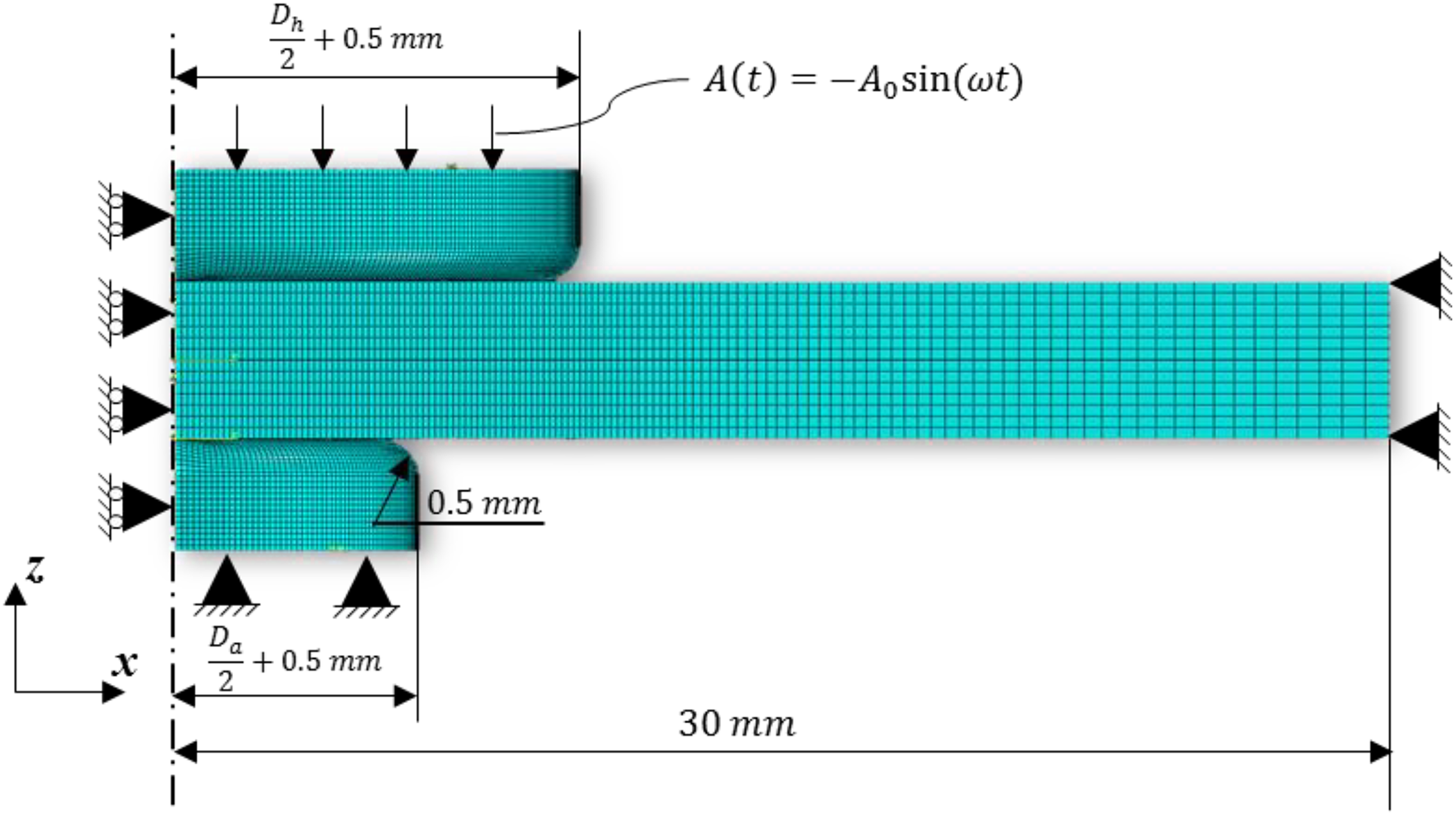
A schematic illustration of the weld configuration for the mechanical simulation.
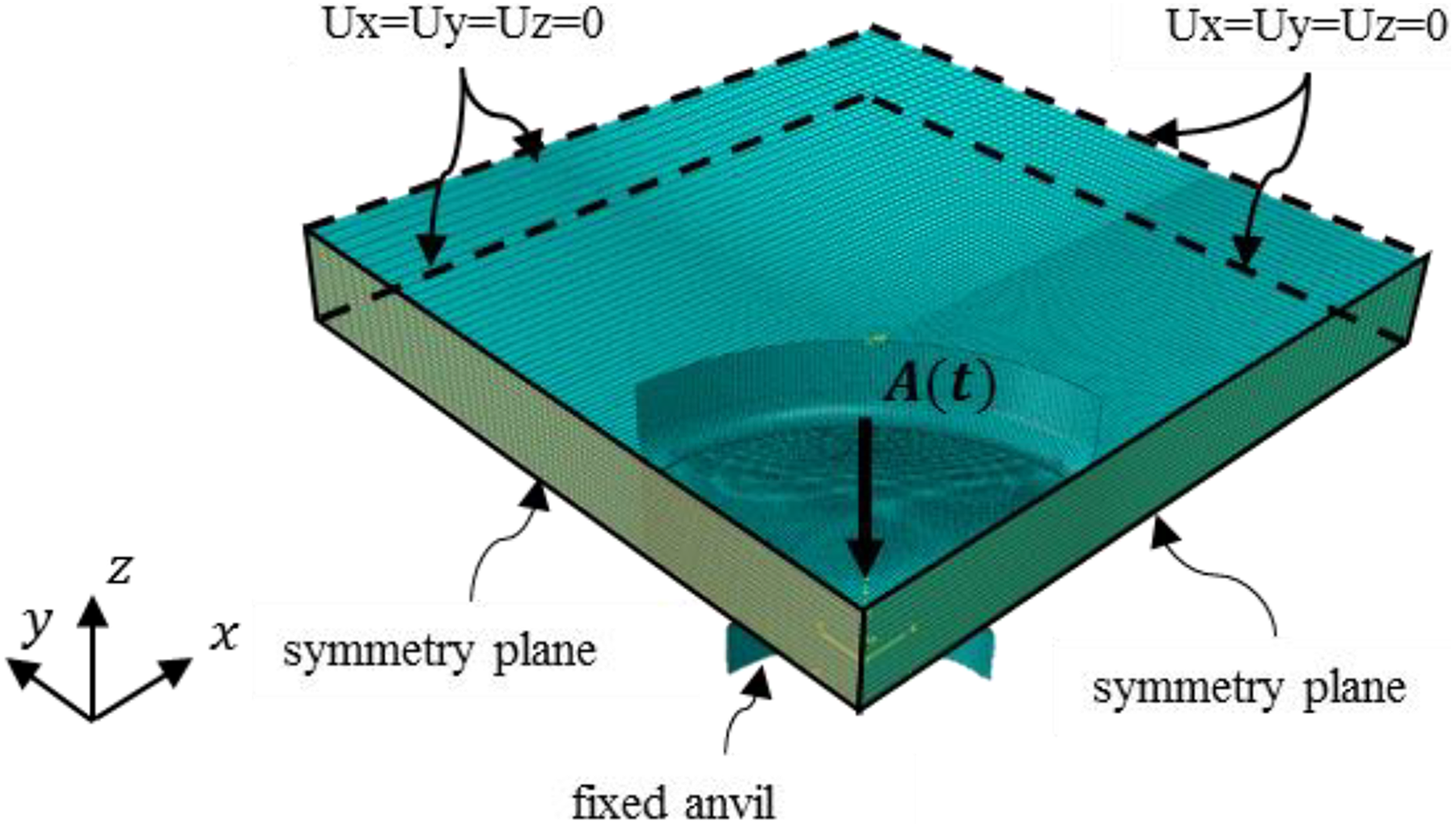
The meshed model with the boundary conditions illustrated.
Due to the doubly symmetry nature of the investigated mechanical problem, the quarter of the laminates were modeled. The symmetry simplification can be considered acceptable for the investigated laminate type because of the balanced cross-ply [0, 90]3 s stacking sequence of the five-harness satin (5-HS) numerical laminate. The symmetry planes are the xz-plane and yz-plane, and they intersect at the axis of rotation z of the cylindrical horn and anvil. The horn and anvil were both modeled as discrete rigid revolved surfaces and only the end part of them were represented in the model. The edges of the horn and the anvil were smoothened with a filet radius of 0.5 mm to avoid excessive stress concentrations at the edges of the contact interfaces. They were meshed with rigid four-node shell elements. This is an acceptable approximation, because their stiffness is almost 20 times larger than the transverse stiffness of the laminates and as well their inertia can be ignored. The interactions between the contact surfaces were defined to be hard contact and tangential-frictional with a friction coefficient of µl = 0.4 for the laminate–laminate contact and µh = 0.2 for the laminate–horn/anvil contacts. It was defined that if the interface shear stresses due to sticking exceed the shear strength of the matrix, then the sticking behavior in the interface at that location becomes a sliding behavior.
The theoretical laminates comprise seven layers of 5-HS carbon fabric-reinforced thermoplastic laminas. In literature, usually a mesoscale model has been used to model the woven fabric laminates. 15,16 However, these models are extremely computational time intensive, especially when simulating complete processes. 17 Therefore, to increase the model efficiency, the material was defined as a laminated composite based on the discrete layer theories. The thickness of the entire laminate was modeled by seven layers of elements. Each element layer represented a 5-HS woven lamina. The mechanical properties of each ply were defined in such a way that an overall laminate property matching a real composite had been resulted.
The preferred element type for the composite laminates for this kind of a dynamic analysis was the 3-D continuum shell with eight nodes and reduced integration with the hourglass effect. Continuum shell elements such as SC8RH are 3-D solid elements with only displacement degrees of freedom and no rotation. They give the possibility to be internally laminated, such as each element is a sub-laminate. They may be stacked to represent the entire laminate thickness and, therefore, can better capture the shear deformations through the thickness. 18
The x and y directions at the region in the vicinity of the weld zone were meshed with elements of an edge size of 0.15 mm. From the boundary of this 10 × 10 mm region and outward, the element size was increased gradually and one-dimensionally until it reached 1 mm at the outer edge. This gradual and one-dimensional size increase in each of the x and y directions has resulted in a bidirectional size growth along the 45° direction of the laminates. The element edge length in the z direction was kept constant at 0.15 mm throughout the entire laminates.
The model was solved using Abaqus explicit dynamic analysis. According to the Abaqus user’s guide, 19 the explicit analysis is computationally effective for problems where the dynamic response time is relatively short, as is the case in the ultrasonic welding process. It performs a large number of time increments where the displacements and the velocities are calculated in terms of known quantities at the beginning of each time increment. The number of time increments was set to be automatic and was determined by the solver. The generated results were stored at equally spaced 400 increments in total.
Through the mechanical model, the deformation shape, the amount of slippage, the interfacial pressure, and the strain distribution were investigated. Snapshots of the deformation shape, pressure, and strain distribution at the maximum compression moment of the second cycle were investigated. Using these results, the influence of the friction heating and the viscoelastic strain heating on the weld initiation were compared. The friction generates a surface heat and the viscoelastic damping generates a volumetric heat. To compare both these mechanisms, the amount of heat input to each element at the interface by each of the two mechanisms per unit of time was calculated. These were plotted as a function of the location of each element. Each element in the interfacial surface is subjected to a surface heat due to the friction


The total heat per unit time
In the third step of the simulation analysis, the influence of the ratio RD
was investigated. The investigated values for the RD
ranged between 1 and 2.2 with an increment of 0.2. The horn diameter was fixed at
Experimental setup
The laminates
The laminate type selected for the simulation models and the experimental analysis was a 5-HS woven carbon fabric-reinforced thermoplastic. It has a nominal 50% fiber volume fraction. The thickness of the laminate
The mechanical properties of the investigated laminate at room temperature.
The in-plane 0° and 90° elastic moduli (

The composite density was given by the manufacturer as to be
Procedure
A commercial ultrasonic welder was used for the experimental studies. The generator had a maximal nominal power of 2400 W with a nominal mean frequency of 30 kHz. The ultrasonic stack consisted of a 30 kHz converter, a 2:1 titanium booster, and a 4:1 steel stepped flat-end horn. The stack provided, according to the laser vibrometry measurements, a maximum base to peak displacement amplitude of
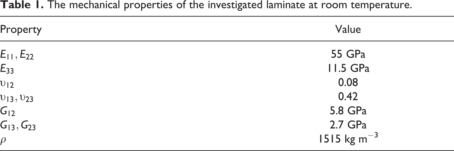
For the experimental investigations, the laminates were cut from a large 600 × 600 mm plate into small stripes with dimensions of 48 × 98 mm. To ensure a uniform water content of all the specimens, they were placed for 96 h in a mechanical convection drying oven at 75°C. Before welding, they were removed from the oven and cooled down to the room temperature. The laminates were placed on top of each other in a crosswise arrangement in a way that ensured the coincidence of their center with the center of the ultrasonic stack. A special flexible clamping tool, as illustrated in Figure 4, was used to fix and position the welded laminates. The base plates holding the two laminates are independent from each other and were fixed to the base through leaf springs. This configuration eliminated the movement of the laminates in the planar direction while allowed the slight movement in the out of plane direction plus the rotation around the two planar axes. This way the parallelism of the laminate pair to each other and to the horn end was ensured.
The clamping device for fixing and positioning the laminates during the welding.
The parameters that are most relevant to the DUS welding were set constant for the investigated cases. To monitor the weld spot size development against time, 13 welds were done with an increasing weld durations in a range between 0.2 s and 1.8 s. At each weld duration case, the weld spot was broken and the resulted spot fracture surface was qualitatively investigated. The breaking of the weld spots was done manually by fixing one of the laminates in a parallel vice and pealing the second laminate with pliers. No forces at break were measured at this stage, and the aim was to observe the weld spot formation. The fracture surface analysis gave information about where and when the thermoplastic matrix diffusion initiated.
Results and discussion
Analysis of the FEM mechanical problem
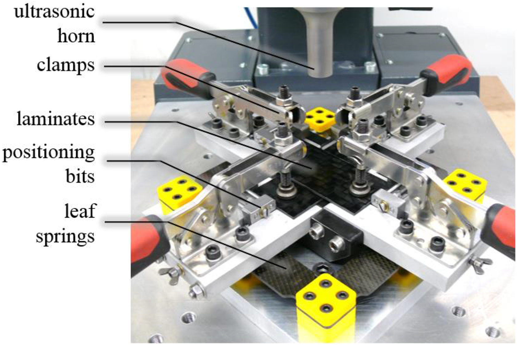
The snapshot of the deformed shape obtained from the FEM dynamic analysis at the moment of the maximum displacement A(t = 5π/2ω) is illustrated in Figure 5 with a scaling factor of 10. This delivers the proof for the bending of the two laminates during the compression phase. The volume inside the imaginary cylinder contained by the radius of the anvil is called the weld center, the volume beyond is called the weld rim, and the boundary between them is the weld apex. The weld center deforms almost solely by compression; at the weld apex, the bending of the laminates initiates and becomes more obvious in the weld rim.
The cross-sectional view of the deformation shape at the maximum compression of the laminates (deformation scale factor 10×, deformation magnitude is given in unit of meters).
The main process variables that contribute to the friction heating are, as given in equation (9), the interfacial slippage and the interfacial pressure. Therefore, the absolute value of the relative movement or slippage amplitude u
0 and the interfacial pressure
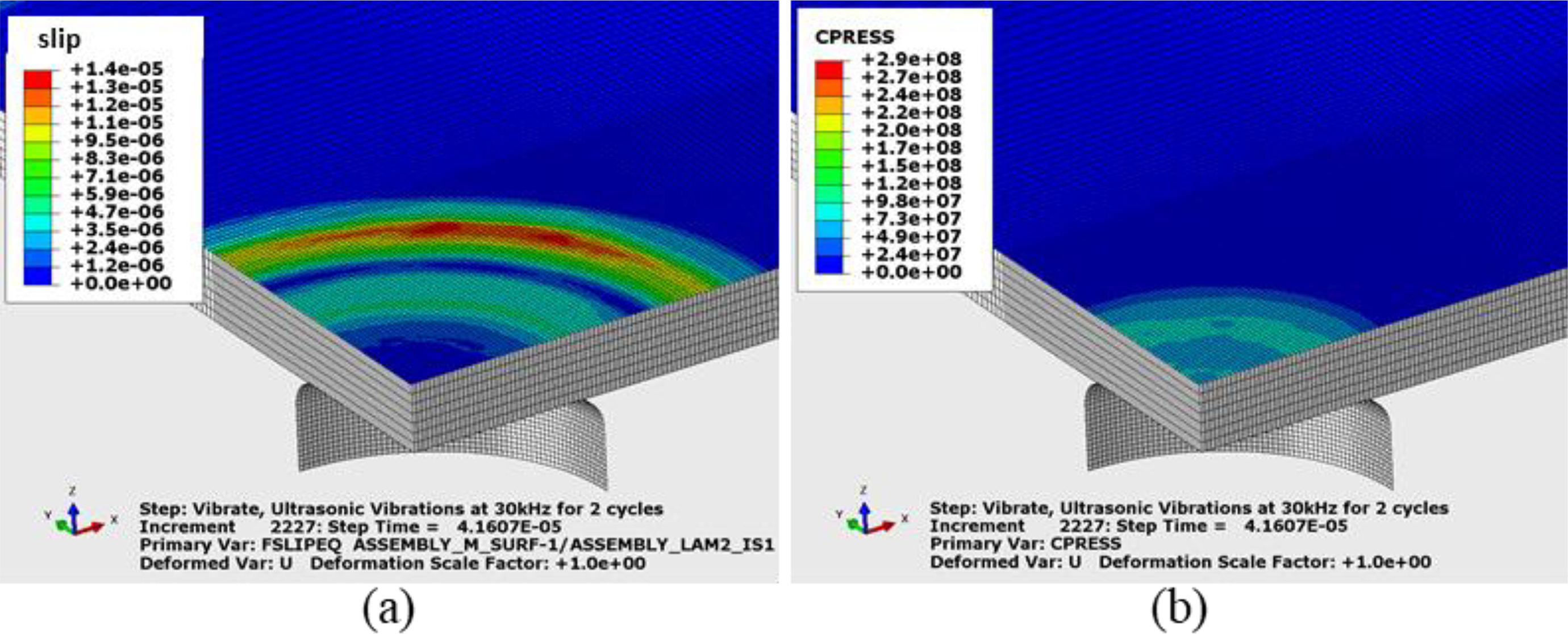
Snapshot of (a) the interfacial slippage and (b) the interfacial pressure at the maximum compression of the laminates during the second cycle (upper laminate and horn are faded out, slip magnitude is given in units of meter, and the pressure magnitude is given in units of Pascal).
It can be traced from Figure 6(b) that the interfacial pressure is almost uniform and restricted in the weld center, whereas the relative movement between the laminates (Figure 6(a)) is mostly focused around the weld apex and in the weld rim. To quantitatively analyze them, the values of the slippage and the pressure were calculated at the nodes located on two paths in the laminate–laminate interface; one along the x-axis (called 0° direction) and the second along a straight path which forms a 45° angle with the x-axis. The values are plotted as a function of the location on the paths for both of the investigated directions in Figure 7. The start points for both of the paths (0 mm) coincide with the axis of rotation of the horn. The plots show that the interfacial pressure amplitude is maximum at the weld spot center, it drops slightly with the increasing location until the location 4.2 mm and then the drop is sharper and reaches null at around the location 7 mm. On the other hand, the slippage amplitude between the two contacting laminates is null in the weld center. The slippage increases gradually with the increasing location and reaches a peak value of 4.53 × 10⁻³ mm around the weld apex. Then the slippage drops slightly up to the 6.3 mm. After this location, the slippage undergoes a slight drop then rises again to higher values. The second rise of the slippage should be in the negative direction. The relative movement changes direction at the location 7.2 mm due to the change of the curvature direction of the bended laminates there (see Figure 5). Because the plotted values are absolute values of the slippage, a positive trend of the curve is observed. It may also be inferred from Figure 7 that the slippage and the pressure along the 45° and the 0° paths are almost identical in profile.
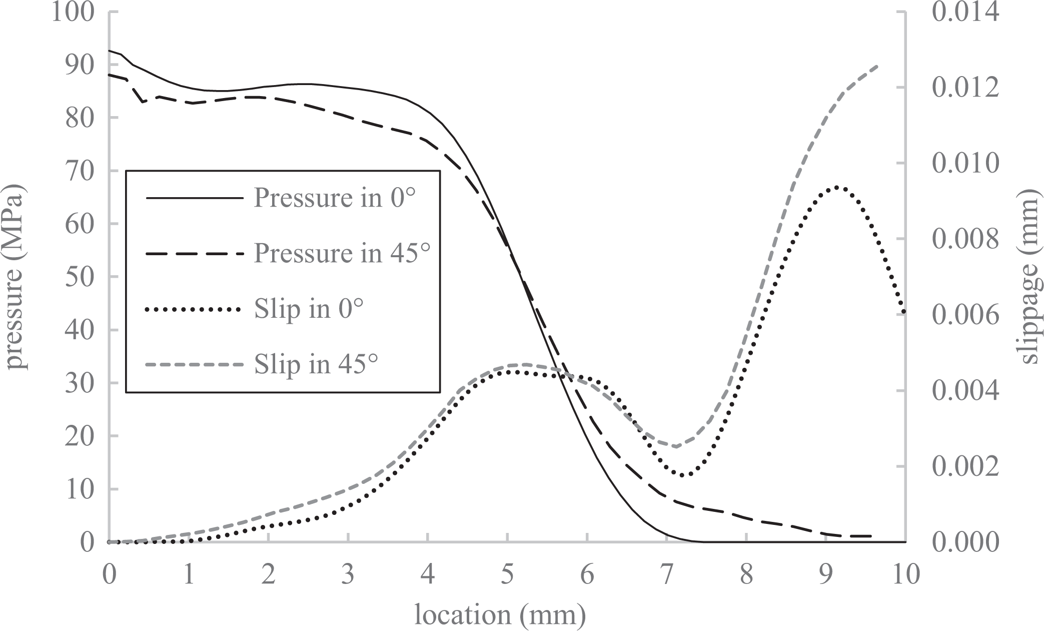
Slippage and pressure in the interface between the laminates in relation to the radial location at the maximum compression instance (0 mm coincides the axis of rotation of the horn).
The strain distribution in the laminates was investigated as the main process variable responsible for the viscoelastic heating. From the illustration at the maximum compression snapshot in Figure 8, it appears that the strain is restricted mostly in the so-called weld center. It is almost homogenous throughout the thickness of both of the laminates. An exception can be noted as a sharp strain concentration in the bottom laminate at its contact location with the edge of the anvil (Figure 8). Refining the mesh at this location did not result to a change in the strain concentration.
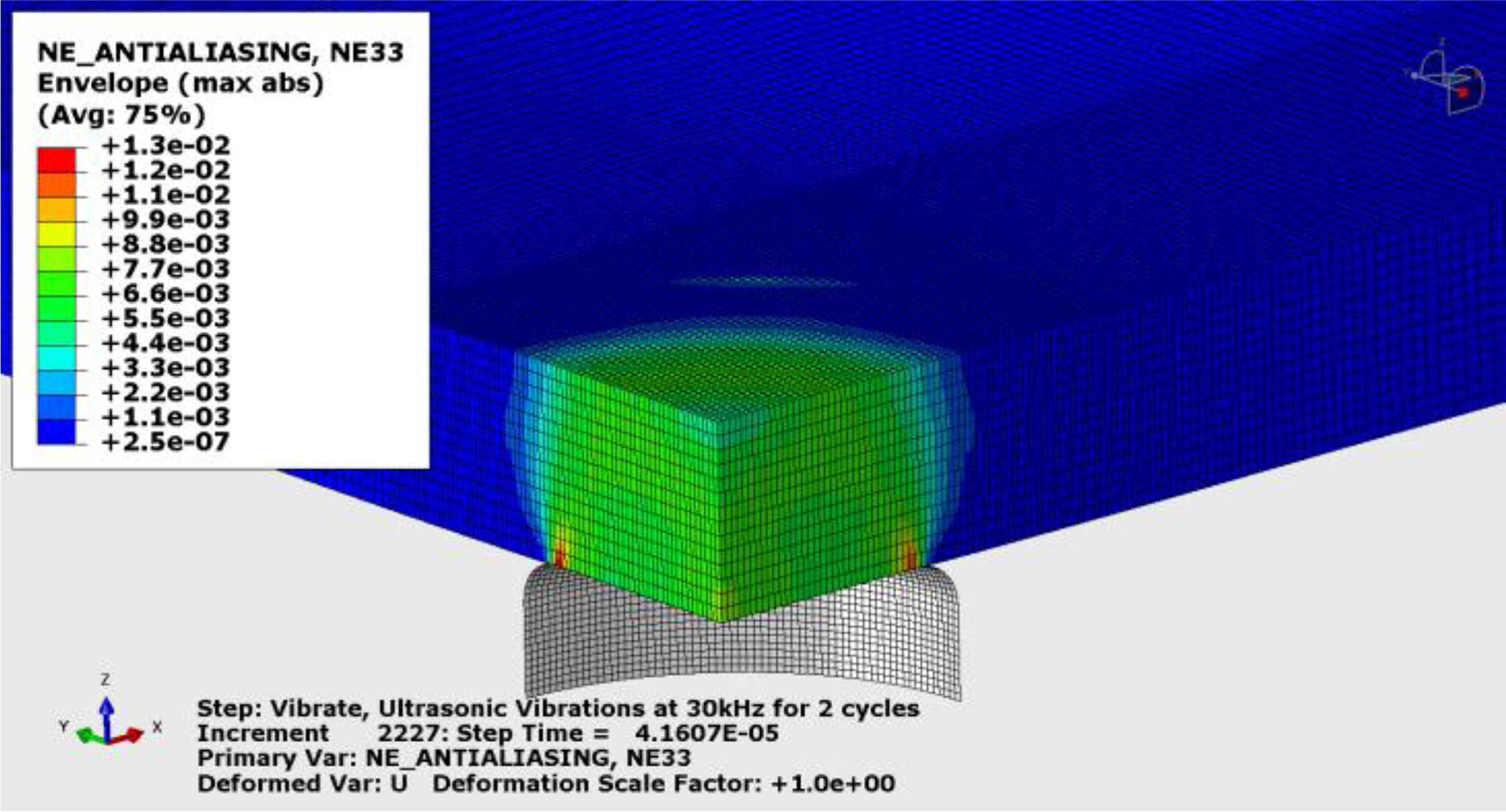
Snapshot of the strain distribution in the laminates at the maximum compression phase of an ultrasonic cycle (horn is faded out).
The strain distribution in the elements at the contact interface between the laminates at a time instance of the maximum compression was projected on the 0° and 45° paths and the results are plotted in Figure 9. It may be inferred that the strain is maximum with an amplitude of 7.4 × 10⁻³ mm/mm at the weld center. The strain outward of this radial location undergoes a slight drop up to 4.4 mm and outside this location drops rapidly to almost zero.
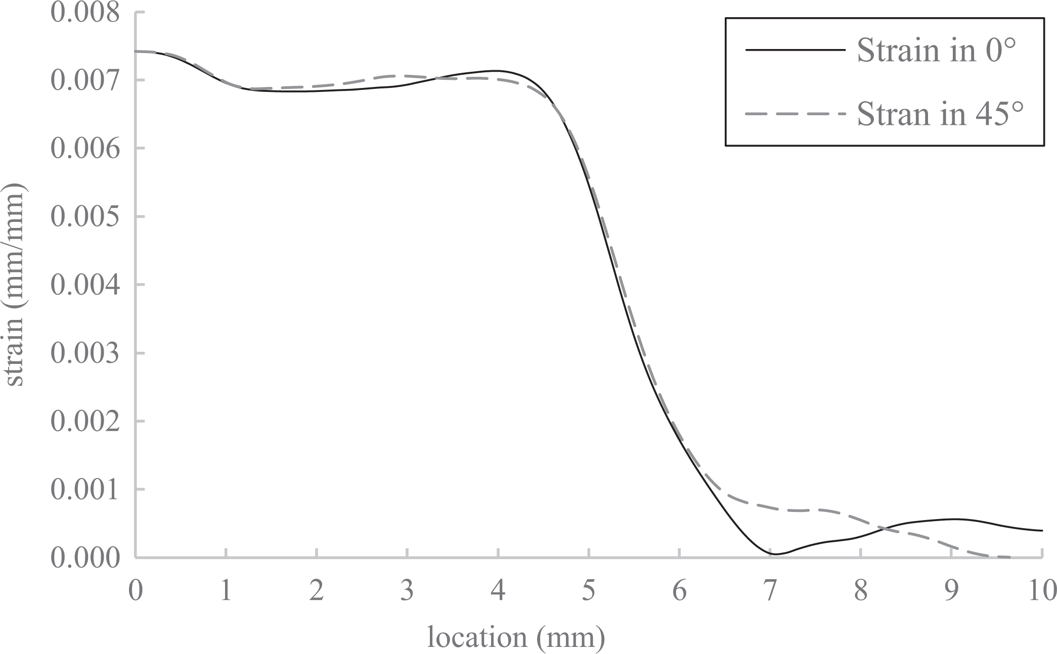
Strain distribution 0° and 45° directions at the time instance of maximum compression as a function of the location.
The viscoelastic heating is volumetric, meanwhile the friction generates a surface heat flux. To compare the influence of these two mechanisms on the DUS welding, the amount of heat generated by each mechanism was estimated for each element located in the weld interface. The calculation for the total heat amount was done for a unit of time using equations (9) to (11). The resulting amounts of heat generated at each element were calculated as a function of the element location along the two paths and are plotted in Figure 10. The plot is valid only for the initial phase of the DUS welding as long as the temperature is well below the glass transition temperature of the matrix. As soon as the temperature exceeds a certain limit, it is most likely that the friction diminishes as the surfaces start to stick to each other.
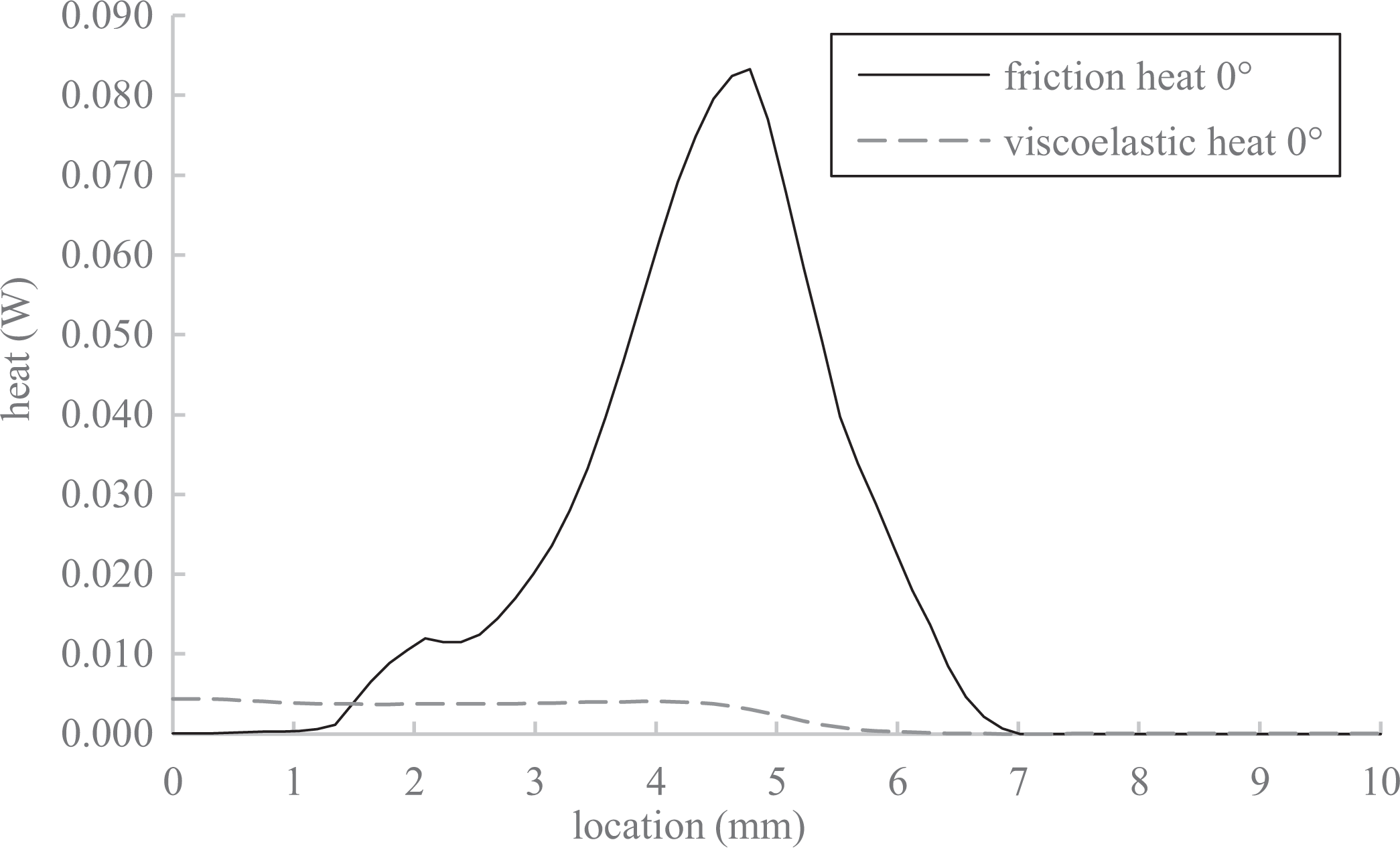
The amount of heat produced per unit time per element in the interface for the 0° direction.
From the plot in Figure 10, one may notice that the friction heat is almost zero at the center of the weld spot and initiates to rise at the elements located around 1.3 mm. From this location outward, the friction heat rises rapidly and reaches an average value on element surface of 0.08 W in the elements located at the weld apex, then it drops and diminishes around 7 mm. The viscoelastic heating, on the other hand, is almost constant throughout the elements at the weld center with a value around 0.0043 W and at locations outside the weld apex the heat generation drops gradually to reach zero. It can be inferred from this analysis that the heat in the initial phase is dominated by friction heating. The calculated friction heat amount per unit time in the elements at the weld apex in the weld interface was about 17 times greater than the volumetric viscoelastic heat for the case of
The most decisive input for the success of the DUS method is the presence of a difference between the horn and the anvil diameters. Therefore, the influence of the ratio RD
on the overall generated heat was intensively investigated. The horn diameter was fixed at
The heat distributions as a function of the location along the 0° path in the laminate–laminate interface at the moment of maximum compression are plotted for the investigated RD
cases in Figure 11. It can be seen from Figure 11 that the
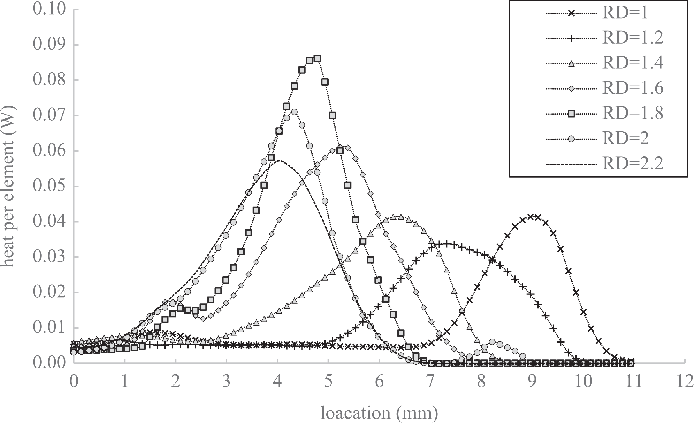
The distribution curve of the total heat per unit time per element at the weld interface as a function of element location. Plotted is the heat distribution for various RD ratios.
The plot in Figure 12 illustrates, on one hand, the maximum generated heat with the two mechanisms per unit time per element and, on the other, the location of the weld apex as a function of the investigated RD
values. The weld apex location value is given on the secondary axis. The weld apex location increases linearly with the reducing RD
, the linearity is true down to the
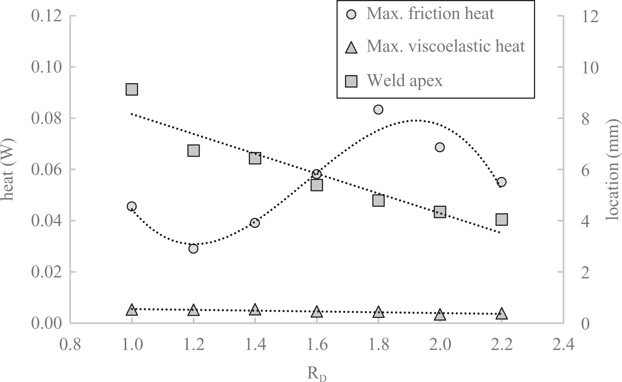
The maximum heat generated per unit time per element by the two mechanisms and the location of the weld apex in relation to the diameter ratio of the horn and anvil.
The experimental analysis of the weld spot development
To investigate the progress of the weld process experimentally, a stepwise investigation was performed. DUS welds were done using different weld duration times ranging between 0.2 s and 1.8 s. The resulting specimens were separated manually and the fracture surfaces were analyzed; the mechanical resistance of the spots was not considered at this stage, only the shape of the weld spots and the development of the weld spots were taken into consideration. A similar approach has been used by Villegas
6
to monitor the joint development between ultrasonically welded laminate pairs. In this investigation, the horn to anvil ratio was
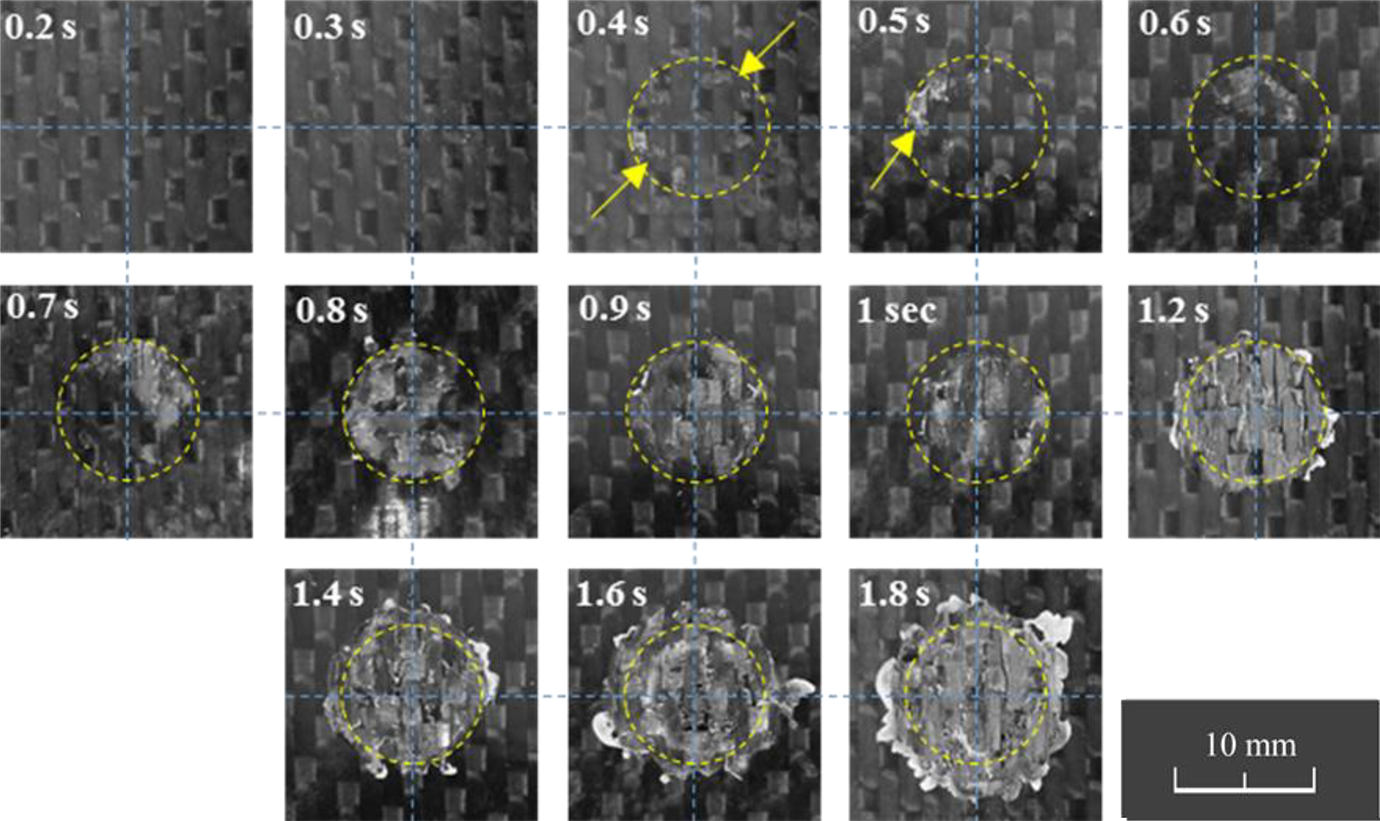
The fracture surfaces of the weld spots for various weld durations. The weld apex is shown as the circle with the dashed yellow line (DUS weld, Dh = 18 mm, Da = 10 mm).
It is assumed that the initial friction heating causes the melting/softening of the matrix at the weld apex. This observation provides the proof and validation of the FEM results. Eventually, the friction heating in turn reduces the stiffness of the interface layers inside the weld center in comparison with the mostly solid and cooler remaining layers, as a result the applied cyclic strain will focus at the softer interfacial layers and induce a much higher viscoelastic heat than the previous stages. Consequently, the heating process will be accelerated and restricted to the weld center in the following stages. As soon as the matrix at the weld apex gets diffused and stick to each other, the friction is most likely eliminated and the heating of the interface is done by viscoelastic strain energy dissipation. This theory gives a suitable explanation for the weld spot formation and development during the DUS process, as depicted in Figure 13.
Conclusions
The DUS method for joining fiber-reinforced thermoplastics was proposed and analyzed in this article by means of mechanical explicit FEM analysis and microscopic analysis. The DUS method eliminates the need for any kind of surface asperities or additional matrix as energy directors in the desired joint location. The focused heat generation at the desired location occurs through the cyclic deformation shape at the weld spot, which in turn is a result of the optimum horn and anvil diameter ratio.
The mechanical analysis served to prove the presence of the friction in the early stages of the weld duration. It was found that under the given geometrical boundaries, the influence of the friction heating at the ring so-called weld apex is larger than the comparable volumetric heat amount with a factor of 17 and as a consequence the melting initiates at this characteristic weld apex. This assumption was further proved through the microscopic imaging of the weld-spot fracture surface. The differential ultrasonic welding, based on the analysis done in this article, can be divided into the following substeps: The maximum friction heating occurs at the weld apex during the weld initiation phase. The temperature increase due to friction heating softens the weld interface. The diffusion of the thermoplastic matrix initiates at the weld apex. As soon as the entire weld center is diffused, the weld spot growth continues outward into the weld rim. Prolonged weld durations cause the overheating and thermal decomposition of the matrix at the weld center.
To further understand the mechanisms governing the differential ultrasonic welding of the thermoplastic composite laminates, a detailed thermal analysis for the entire DUS weld duration is essential.