
Abstract
A novel dry phantom nanoconducting composite that can simulate the effect of electromagnetic wave on human tissues composed of graphite/nickel (GN) nanoparticles and polyvinyl chloride (PVC) was successfully fabricated. The morphology of as-synthesized graphite nanosheets and PVC/GN composites was investigated by means of scanning electron microscope. Dielectric parameters such as relative permittivity, imaginary permittivity, and alternating current conductivity are evaluated in the frequency range of 0.5–12 GHz. The results are compared with the in vitro equivalent human tissue data and good agreement is reported. The absorption and reflection coefficient as a function of frequency of nanocomposites were also studied. The novel PVC/GN nanocomposites have potential applications for dry phantom and the coupling media in microwave medical imaging.
Keywords
Introduction
Nanoconducting composites have received increasingly more attention for their potential applications as practical structural and functional materials. 1 –5 Today, research and development are performed with a high-speed and high-capacity communication using higher frequencies than the frequency band previously used in communications and broadcasting. 6 –10 One example is using ultra-wideband (UWB) technology, which is the next-generation of communication system. UWB technology mainly focuses on short-range, high-capacity indoor communications, communicates using pulses with narrow time widths, and uses a wide frequency bandwidth of 3.1–10.6 GHz. 11 –15 Conductive polymer nanocomposites are becoming increasingly useful because of their unique combination of metallic conductivity and polymer properties. These materials are widely used as microwave absorbing materials, electromagnetic shielding materials, antistatic materials, and others. 1 –5 Graphite is layered minerals composed of weakly bonded large number of graphene sheets that are held together by van der Walls forces with a large aspect ratio. 9,10 Some of the nanocomposite materials suitable for use in vivo as artificial organs and tissues have been an intriguing topic of research in recent years. 16 –20 The human tissues can be classified into two categories: low water content tissues such as fat and skull and high water content tissues such as brain and muscle. 1,2 There are several types of phantoms that are already in use as tissue substitutes for microwave medical imaging. 16 –20 These compounds composed of polyethylene and/or agar contain sodium chloride and water, and the other phantoms from ceramics. 6,7 The disadvantage of these kinds of phantoms material are that they decompose overtime, cannot form hard ceramics easily, variability between repeated dilutions and inhomogeneities from air bubbles or precipitants, and long setup times. 8,9 The phantom material should have the same dielectric properties such as relative real permittivity and conductivity, shape, and size similar to human tissues. 2 –4 Because the relative real permittivity and conductivity are material constants depending on a given frequency, it is very important to understand the dielectric characteristics of the materials in constructing the phantom model. Tell now, there are no published reports on the fabrication of PVC/GN nanocomposites for phantom materials. In this article, a new dry phantom nanoconducting composite of graphite/nickel (GN) nanoparticles reinforced polyvinyl chloride (PVC) was fabricated. The influence of GN content on the microstructure and structure was investigated in terms of scanning electron microscopy (SEM). The applicability of PVC/GN composites as a dry phantom and microwave imagining devices were examined in details in the frequency range from 1 to 12 GHz.
Experimental details
Material description
Natural flake graphite with an average diameter of 500 µm and surface area of 46 m2/g used for preparing the expanded (exfoliated) graphite is purchased from Shandong Qingdao Graphite Company (Qingdao, China). Commercial concentrated sulfuric acid and nitric acid from Egyptian Chemical Company (Cairo, Egypt) was used as chemical intercalant and oxidizer to prepare exfoliated graphite. The 95% (v/v) alcohol and distilled water were used as solvents for the preparation of foliated (nanosheets) graphite. PVC was obtained from Tokyo Chemical Industry Co. Ltd (Tokyo, Japan). Nickel powder was supplied by Wako Chemical Company with particle size 10 µm.
Preparation of exfoliated graphite
Natural flake graphite was first dried in a vacuum oven for 24 h at 100°C. Then, a mixture of concentrated sulfuric acid and nitric acid (ratio 4:1, v/v) is added slowly to a glass flask containing graphite flakes with vigorous stirring. After 24 h of reaction, the acid-treated graphite flake was filtered and washed with deionized water until the pH level of the solution reached 6.4. After being dried at 100°C for 24 h, the resulting graphite intercalation compound was subjected to a thermal shock at 1100°C for 50 s in a muffle furnace to form exfoliated (expanded) graphite with surface area of 141 m2/g.
Preparation of foliated graphite nanosheets
We sonicated the expanded graphite in alcohol solution to gain shiny graphite powder. In a typical synthetic procedure for foliated graphite nanosheets, 1 g of exfoliated graphite was mixed and saturated with 400 ml alcohol solution consisting of alcohol and distilled water with a ratio of 70:30 for 24 h. Then the mixture was subjected to ultrasonic irradiation with a power of 400 W for 24 h. After 24 h of sonication, exfoliated graphite particles were effectively fragmented into foliated (nanosheets) graphite. The foliated graphite dispersion was then filtered and dried at 100°C to remove residual solvents. The as-synthesized foliated graphite powder is called graphite nanosheets in this study.
Preparation of nickel nanoparticles
The starting material for ball milling is Ni (250 mesh) with the purity of above 99.9%. These Ni powders were placed in stainless steel vials with stainless steel balls of 10 mm diameter. The ball-to-powder ratio of 15:1 was mixed mechanically in a planetary miller (Marconi MA 350 ball miller) at 400 r/min under argon atmosphere for 10 h.
Preparation of PVC/GN nanocomposites
The conducting fillers utilized here are composed of graphite nanosheets with an average thickness of about 30–50 nm and Ni with an average particles size of 30 nm. First, mixtures of as-prepared graphite nanosheets with conducting nickel nanoparticles 90/10 wt% were grinded together in a grinding machine for 4 h. Second, the as-received conducting mixture were added to the PVC matrix and mixed by grinding machine for 30 min. Then the mixture transferred to a hot press at 200 KN/m2 at temperature of 170°C for 10 min. Several batches of PVC/GN weight ratios were considered: 97:03, 94:06, 91:09, and 88:12, respectively, and abbreviated as GN3, GN6, GN9, and GN12, respectively.
Instruments
The morphology of composites was analyzed using a scanning electron microscopy (SEM, JSM-5310 LVB, JEOL). The specimens were coated with carbon to avoid charging using a vacuum evaporator (JEOL, GEE 500) and the voltage used was 15 kV. The microwave dielectric properties of composites were determined by the Hewlett-Packard waveguide line containing spectroanalyzer, power meter, coefficient of reflection meter, and coefficient of attenuation meter with an accuracy of 0.1. The measurements were carried out in the frequency ranges 1–12 GHz using the cavity perturbation techniques. The sample dimensions were 20 × 20 × 0.5 mm3.
Results and discussion
Dielectric properties of PVC/GN nanocomposites
Dielectric constant of a composite is a parameter to describe the polarization degree of the composite, which is proportional to the composites dipole polarization.
1
–3
Figure 1 depicts the variation in real permittivity
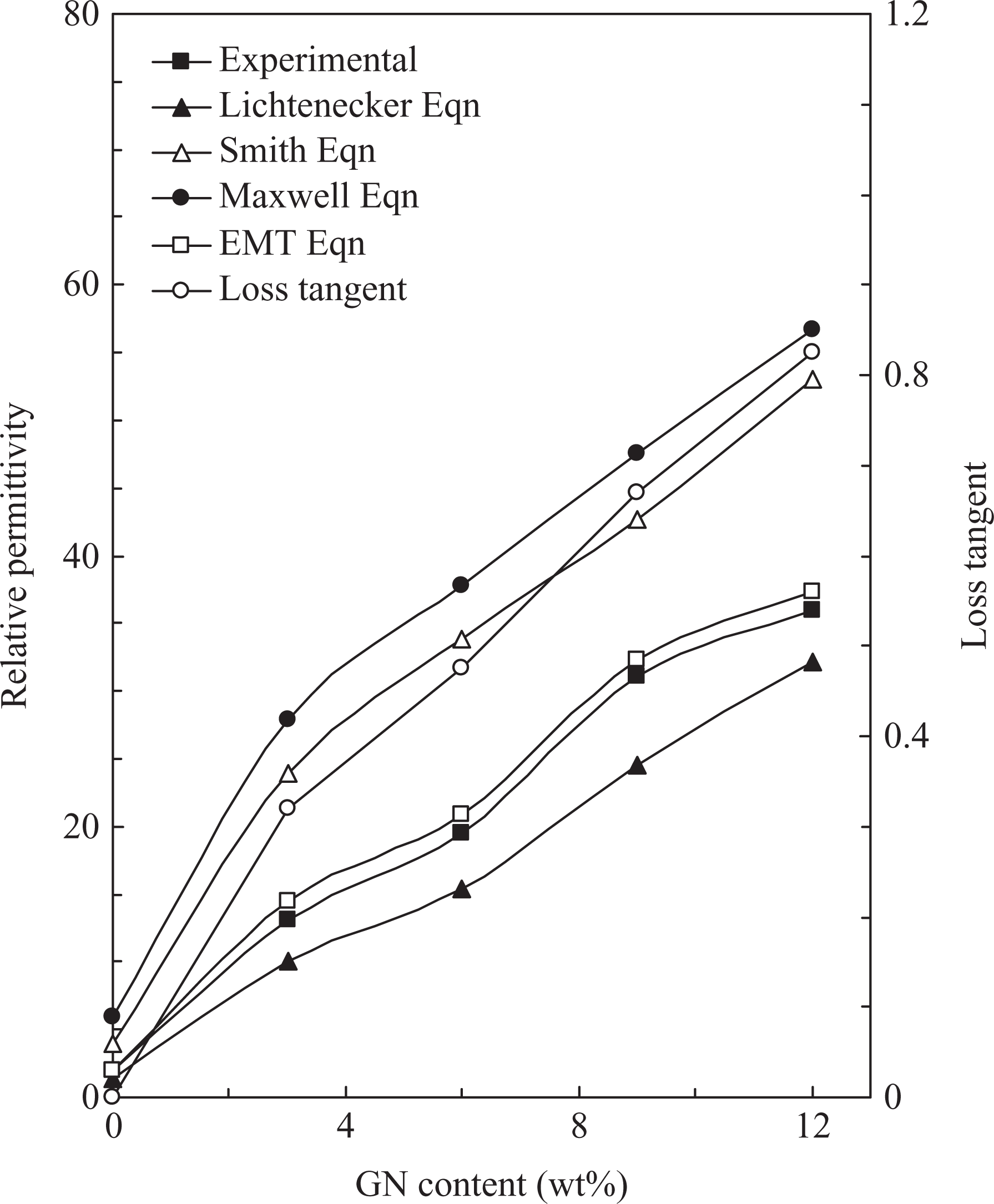
Comparison of experimental and theoretical relative permittivity of PVC/GN nanocomposites and loss tangent against GN content. PVC: polyvinyl chloride; GN: graphite/nickel nanoparticle.
The typical scanning electron micrographs of as-synthesized foliated graphite nanosheets and GN12 sample are depicted in Figure 2(a) and (b), respectively. In Figure 2(a), we can clearly observe that the ultrasonic radiation breaks down the worm-like structure and to reduce its size, resulting in individual graphite nanosheets. It revealed that the expanded graphite was tore to sheets with an average diameter of 10 µm obtained from x-ray analysis. Typical SEM image of GN12 sample is depicted in Figure 2(b). In Figure 2(b), it is clear that PVC chain is effectively incorporated into the galleries of GN layers. Furthermore, we can clearly observe that the GN nanoparticles were distributed quite uniformly within the PVC matrix and no aggregates can be seen in the composite. Because of this special structure, the interfacial affinity of GN nanoparticles with the PVC matrix increased and led to an ensured thermal stability and electrical contact that served as the electrically conductive bridge. 1,12
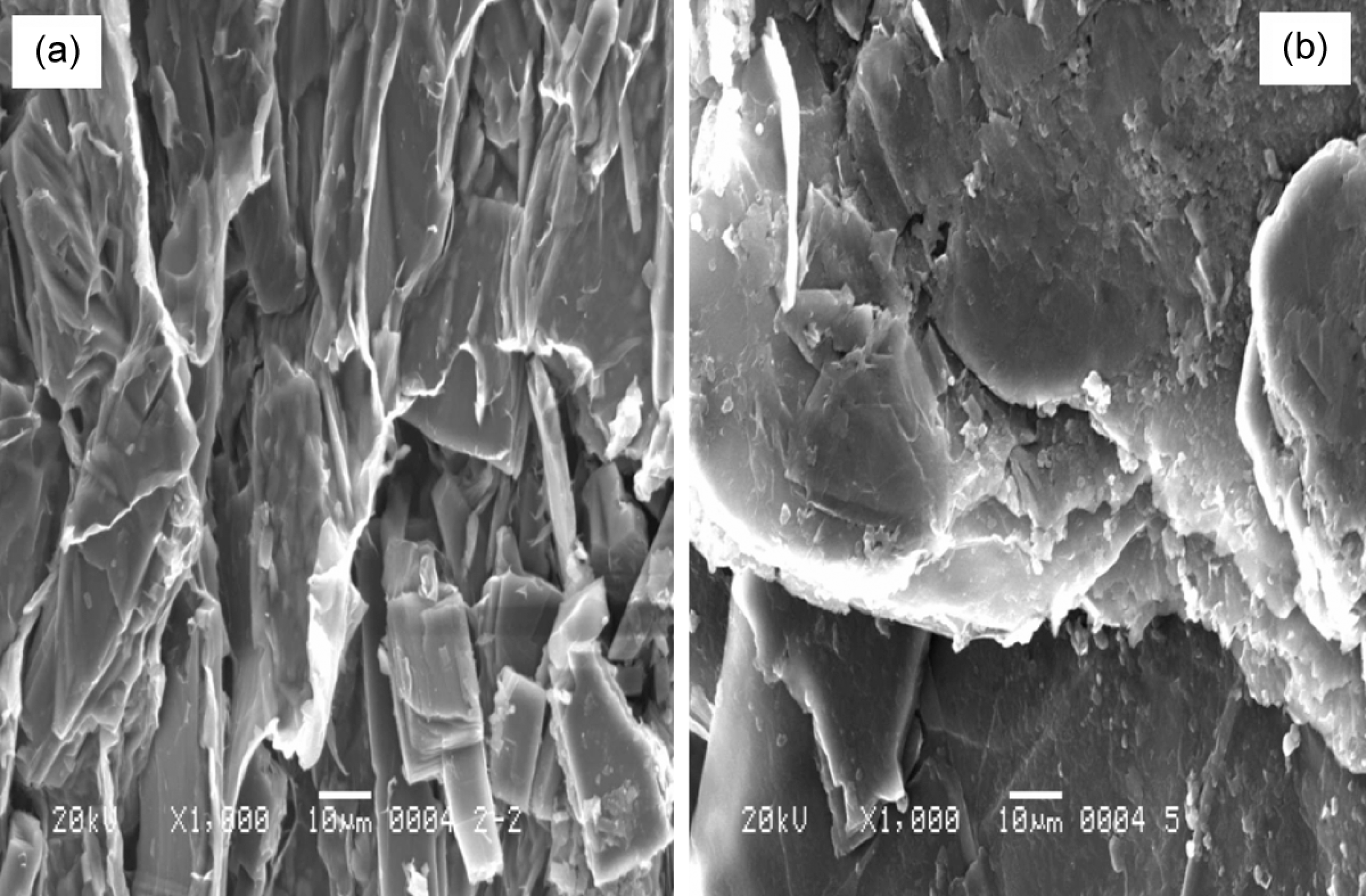
SEM image of (a) as-prepared graphite nanosheets and (b) SEM image of GN12 sample. SEM: scanning electron microscopy; GN: graphite/nickel nanoparticle.
Meanwhile, there are a number of theoretical models to predict the effective real permittivity of the composites. In this study, the following equations were used to evaluate the effective relative permittivity of the PVC/GN nanocomposites.
Lichtenecker (logarithmic mixing) model is given by the equation
21,22

Smith’s mode is given by the equation
23
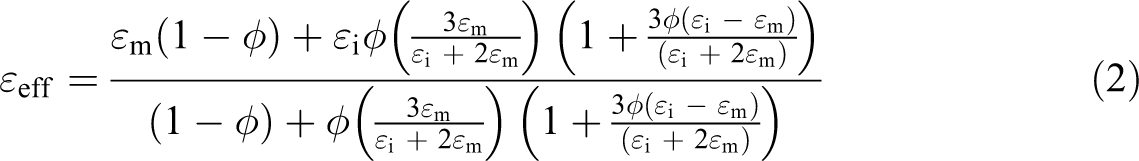
Maxwell Garnet model is given by the equation
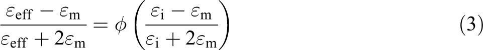
Effective medium model is given by the formula

where ε eff, ε I, and ε m are the permittivity of the nanocomposites, the GN filler, and the PVC matrix, respectively, φ is the volume fraction of the GN fillers, and n is the correction factor to compensate for the shape of the fillers used in polymer composites.
In Figure 1, it is observed that the measured relative permittivity shows a deviation from the predicted values for Lichtenecker, Smith’s, and Maxwell models. This is due to the fact that the complex permittivity depends on several factors like homogeneity and dispersion of filler, aspect ratio of filler, polarity of filler and matrix, morphology of filler, size of filler, interface bonding among filler and matrix, extent of filler reinforcement, and others. 20 –24 The reason is that the Lichtenecker model does not consider the filler/matrix interface adhesions, and it is only valid in the case of the filler and matrix having close value of relative permittivity. But smith’s model can not predict the permittivity values of PVC/GN nanocomposites precisely. This can be due to the fact that the used conducting GN fillers are not spherical but in sheet form. 21 The Maxwell Garnet model also gives a considerably lower estimate for the measured relative permittivity of PVC/GN naocomposites. This can be due to the various factors, which affect the relative permittivity of the nanocomposites other than GN filler volume fraction and permittivity of GN fillers. Among the four models, the experimentally observed relative permittivity is in excellent agreement with that computed using the effective medium theory. The obtained value of n for PVC/GN nanocomposites is about 0.67.
Figures 3 and 4 depict room temperature plot of relative permittivity and imaginary permittivity of PVC/GN nanocomposites as a function of frequencies in the range of 0.5–12 GHz, respectively. The relative permittivity of green PVC is nearly frequency independent. Clearly, the relative permittivity and imaginary permittivity increased with an increase in the GN volume fraction into nanocoposites. It is observed that both the relative permittivity and imaginary permittivity decrease with increasing frequency. This result coincides with the studies on dielectric properties of biological tissues. 5 –8 The low dielectric constant of green PVC is attributed to the low polarizability of the molecular segments of PVC polymer. The decrease in relative permittivity with an increase in the frequency is attributed to the orientation of the polarization in the microwave field. 20 At relatively low microwave frequencies, the total polarizations by electronic, atomic, and orientation polarization take place. One the other hand, as the frequency of the applied field increased, the total polarization decreases into composites. This leads to dielectric relaxation, which in turn, leads to a decrease in relative permittivity. Furthermore, at high frequencies due to the rotational displacement of polar groups under the influence of the electric field, frictional loss increases and it reduces relative permittivity. It is interesting to mention that, when PVC/GN is mixed in definite proportions, the relative permittivity and conductivity increases and behaves as an ideal stimulant of low and high water content biological tissues.
Relative permittivity at room temperature of PVC/GN nanocomposites as a function of frequencies in the range of 0.5–12 GHz. PVC: polyvinyl chloride; GN: graphite/nickel nanoparticle.
Imaginary permittivity at room temperature of PVC/GN nanocomposites as a function of frequencies in the range of 0.5–12 GHz. PVC: polyvinyl chloride; GN: graphite/nickel nanoparticle.
The conductivity can be related to the imaginary part of the complex dielectric constant

The dependence of the alternating current (AC) conductivity of the PVC/GN nanocomposites on frequency is depicted in Figure 5. The AC conductivity is found to increase with an increase in frequency. This is due to a large dipole moment of the nanocomposites with increasing GN nanoparticles. The AC conductivity of dielectric materials in microwave frequency depends upon the dielectric loss factor. Here, as frequency increases, the dielectric loss factor also increases. The dielectric loss is a direct function of the relaxation process, which is due to local motion of polar groups. 21,22 At high frequencies, the friction between molecular chain increases, which leads to higher dielectric loss. This dielectric loss factor causes the so-called conductivity relaxations. At this relaxation region, the polarization acquires a component out of phase with the field and displacement current in phase with the field, resulting in the thermal dissipation of energy, thus generates dielectric loss and thus AC conductivity increases.
AC conductivity versus frequency of PVC/GN nanocomposites. AC: alternating current; PVC: polyvinyl chloride; GN: graphite/nickel nanoparticle.
The equivalent phantoms for various low water content biological samples in the frequency range of 2–3 GHz are given in Table 1. 23,24 Comparison of our results with different equivalent phantoms is recorded in Table 1, it is noteworthy that the mixing of graphite nanosheets with nickel nanoparticles in definite proportions with PVC can simulate phantoms of any of these biological tissues. It can be directly related to its higher water content compared with that of green PVC and PVC/GN nanocomposites. Human chest fat, bone marrow, and brain fall in the same dielectric range as GN3, GN6, and GN9, respectively (Table 1). These composites are noncorrosive, easy to make, and cost effective, and thus can be used as suitable dry phantom for biological tissue in microwave medical imaging devices.
Relative real permittivity and electrical conductivity of biological tissues and equivalent phantom from our work in the frequency range 1–3 GHz.5–12
Absorption and reflection coefficients of nanocomposites
In order to provide a sound fact for the application of nanocomposites as a phantom material, the microwave properties like absorption and reflection loss was analyzed on the basis of the observed absorption and reflection loss with applied frequency. The absorption and reflection coefficients of composites depend on microstructure, type, morphology of fillers, and so on. 1 The absorption and reflection coefficients versus frequency of nanocomposites are depicted in Figures 6 and 7, respectively. In Figure 6, it is observed that the addition of GN particulate improves the absorption coefficient of nanocomposites and the increment varies with increasing frequency in frequency range 1–12 GHz. The GN12 sample exhibits good absorption rate due to its high value of conductivity and relative permittivity. Thereof the PVC/GN nanocomposite is ideal to use as absorbing material in the microwave tomographic imaging. 10 –12 Furthermore, the high absorption coefficient of PVC/GN nanocomposites could be attributed to the nanosize-confinement effect, which may also have contribution to the high absorption coefficient of nanocomposites. 13,14
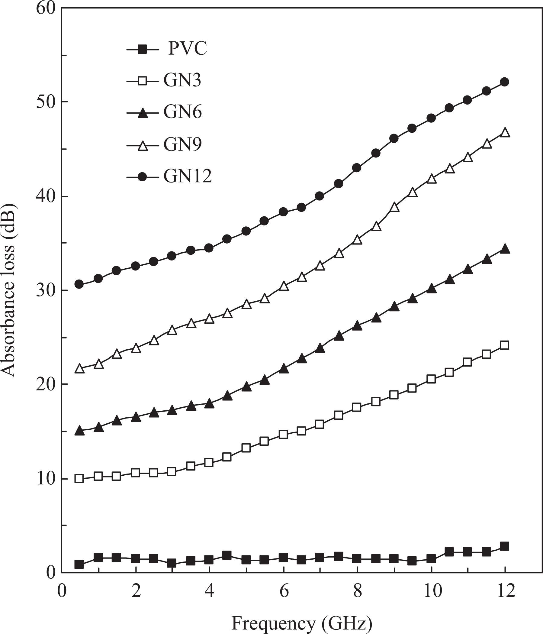
The absorption coefficients versus frequency of PVC/GN nanocomposites. PVC: polyvinyl chloride; GN: graphite/nickel nanoparticle.
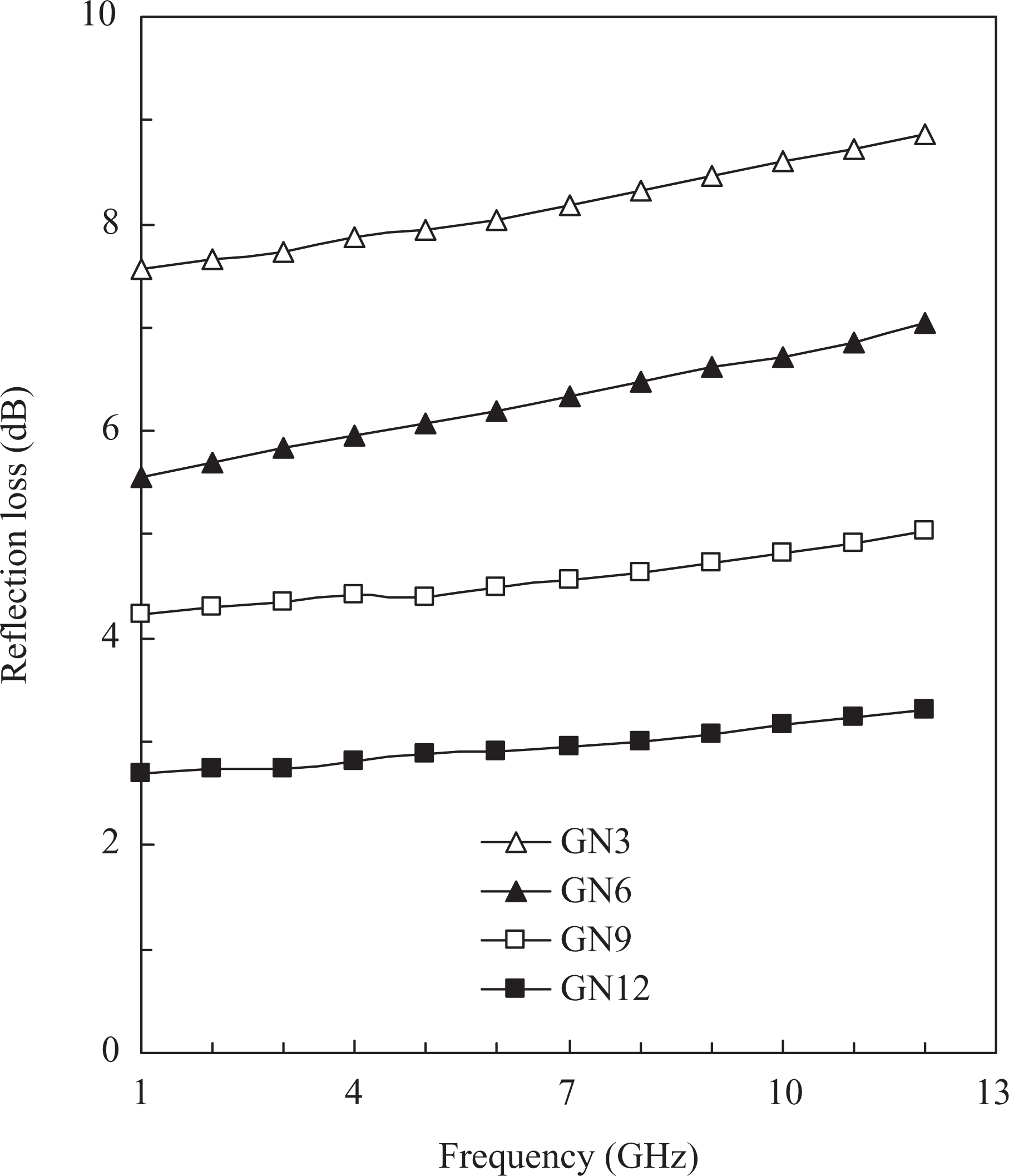
Reflection loss versus frequency of PVC/GN nanocomposites. PVC: polyvinyl chloride; GN: graphite/nickel nanoparticle.
In Figure 7, it is seen that the reflection loss decreases with increasing GN content into composites. This phenomenon is due to the increase in cross-link density and interfacial bonding among filler and matrix with increasing GN content into composites.
Conclusion
The inclusion of GN nanoparticles enhances the microstructure of PVC composites. Dielectric parameters such as relative permittivity, imaginary permittivity, and AC conductivity are evaluated in the frequency range of 0.5–12 GHz. The results are compared with the in vitro equivalent human tissue data and good agreement is reported. The PVC/GN nanocomposites are good absorbers of electromagnetic waves in the microwave band frequency up to 12 GHz. Many exciting new technologies can be realized through the use of PVC/GN nanocomposites, extending the already extensive range of applications of dry phantom for medical images, as absorbers in microwave imaging chamber at microwave frequency.
Footnotes
Authors’ Note
The present research is a result of an international collaboration program between the University of Tabuk, Tabuk, Kingdom of Saudi Arabia and the University of Chemical Technology and Metallurgy, Sofia, Bulgaria.
Funding
This work was supported by the University of Tabuk, Tabuk, Kingdom of Saudi Arabia.