
Abstract
A combined theoretical–semiempirical penetration model of ballistic penetration of thick section composites has been developed. The penetration model is developed by breaking down the penetration event into two major phases, that is, (i) the short-time phase I shock compression and (ii) the long-time phase II dynamic penetration. Phase I shock compression considers a one-dimensional stress wave propagation theory and the rate effects on material properties. On the other hand, the phase II dynamic penetration phase incorporates a dynamic increase factor to a semiempirical quasi-static penetration resistance curve. The combined theoretical–semiempirical penetration model is compared with finite element analyses of the same problem and good correlations are obtained.
Keywords
Introduction
Terminal ballistics1–6 of finite thickness targets seek theoretical solutions for (i) the ballistic limit velocity (
Ballistic limit velocity of a finite thickness target–projectile pair is mostly determined experimentally. In a semiempirical equation in the CGS (centimeter-gram-second) unit formulated by DeMarre and later modified by Lambert for metals, 1 the parameters should be determined experimentally for each projectile–target pair. A theoretical model was proposed by Forrestal et al. 10 which can predict the residual velocity of a long rod penetrating the aluminum targets within 15% accuracy. Florence 11 developed a simplified model for ceramic–aluminum targets impacted by a short cylindrical projectile. A more rigorous model is proposed by Walker and Anderson 12 which require solving complex equations and writing a computer program and later Zaera and Sanchez-Galvez 13 used Tate’s equation to develop a penetration model for ceramic–metal targets.
For impact velocities higher than the ballistic limit, Recht and Ipson 14 and Lambert and Jonas 15 equations are usually used to predict the residual velocity of the projectile.
Both the Recht and Ipson and Lambert and Jonas models are mostly used in curve fitting the ballistic experiments. Both simple and complex models have been used to predict the ballistic limit for metals, two-component ceramic–composite armor, fabrics and soft laminate16,17; however, the focus of the present research is to develop penetration models for thick section composites.
While multiscale computational analyses (both Lagrangian and Eulerian) can be used to solve the governing equations of motion and model the physics of penetration under high- and hyper-velocity impacts by modeling the constitutive behavior of the materials, equation of state (EoS), failure mechanisms, and so on18–32; theoretical solutions are necessary to reduce the computational time and to perform parametric calculations.
For thin section composites, some theoretical models are available33–40 to predict the ballistic limit and projectile dynamics, but for thick section composites under ballistic impact, we could not find any suitable model that can predict the ballistic limit and projectile dynamics.41–45 A recent theoretical model39,40 assumes the penetration of thin composite laminates and uses the conservation of energy and momentum to balance the energy dissipated by different composite damage mechanisms. This model predicts the ballistic limit, and projectile dynamics with some accuracy, however, cannot be used for thick section composites, in which the through-thickness stress wave propagation in the early stage of impact needs to be considered in predicting the initial impact contact force and projectile dynamics. In this regard, we have developed a punch shear–based penetration model
44
for ballistic penetration, and a detailed three-dimensional (3D) finite element analysis (FEA) of impact and penetration of thick composites.
46
While the punch shear–based penetration model
44
can predict the ballistic limit but not the projectile dynamics, the 3D FEA with progressive composite damage material model MAT162
46
can model the correct stress wave propagation and different energy-dissipating damage mechanisms of composites
47
such as matrix cracking, delamination and fiber fracture under combined tension shear, compression shear, punch shear, and crush. Our 3D FEA work
46
has predicted the projectile dynamics and the PR force as a function of time for a wide range of impact velocities. From these two experimental and FEA work44,46 and also from other literature cited, ballistic impact and penetration of a composite laminate under a right circular cylinder projectile can be described in two major phases, that is (i) the short-time phase I—shock compression and (ii) the long-time phase II—penetration and perforation. In our experimental work, we have found that the ballistic limit velocity of a 13.2-mm-thick plain weave (PW) S-2 glass/SC15 composite under the impact of a 0.50-cal right circular cylinder of mass 13.8 g is
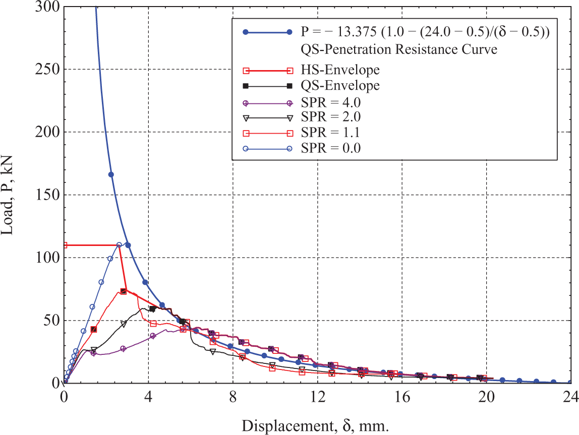
Quasi-Static Penetration Resistance (QS-PR) curve as a function of punch displacement for plain weave (PW) S-2 Glass/SC15 composites. QS-PR curve is obtained from a series of quasi-static punch shear tests (QS-PSTs) on composite specimens of same thickness as a function of circular support span to punch diameter ratio,
Through these works, we have identified that there is no theoretical model for composites that can predict the impact force during the impact contact or shock phase, and this is the subject matter of the present article. We have obtained closed form theoretical solution for the shock phase and are also developing theoretical models for the subsequent phases. Since a theoretical model for the later phases are not available yet, we have adopted our quasi-static PR (QS-PR) curve (Figure 1) with a dynamic increase factor (DIF) to develop the present combined theoretical–semi-empirical model of ballistic penetration, which can predict the ballistic limit of a thick section composite plate and can also predict the projectile dynamics at the ballistic limit.
A combined theoretical–semiempirical penetration model of ballistic penetration
Previous finite element modeling 46 has identified that the phase I shock stress increases with an increase in impact velocity, and the amplitude of the phase II PR force (with an exponential decay behavior) also increases with an increase in impact velocity. In order to capture the projectile dynamics, stress wave propagation, and PR force as a function of impact velocity; a theoretical one-dimensional (1D) shock compression model for phase I and a semiempirical model for phase II are proposed and are presented in this section.
1D phase I shock compression model of projectile impact on composites
The impact contact force on the projectile as a function of initial impact velocity is the primary unknown quantity during phase I. We will consider stress wave propagation in both the projectile and the composite plate upon impact and also consider a rate-dependent elastic–plastic strain hardening constitutive equation to describe the through-thickness compression behavior of the composite and derive an analytical expression for the PR force. Knowing the PR force as a function of time, the projectile dynamics during penetration will also be evaluated.
Following the rigid projectile models of Galanov et al.
48
and Lopatnikov et al.
49
for 1D failure/shock wave propagation, we will consider elastic stress wave propagation in a right circular cylinder projectile of mass
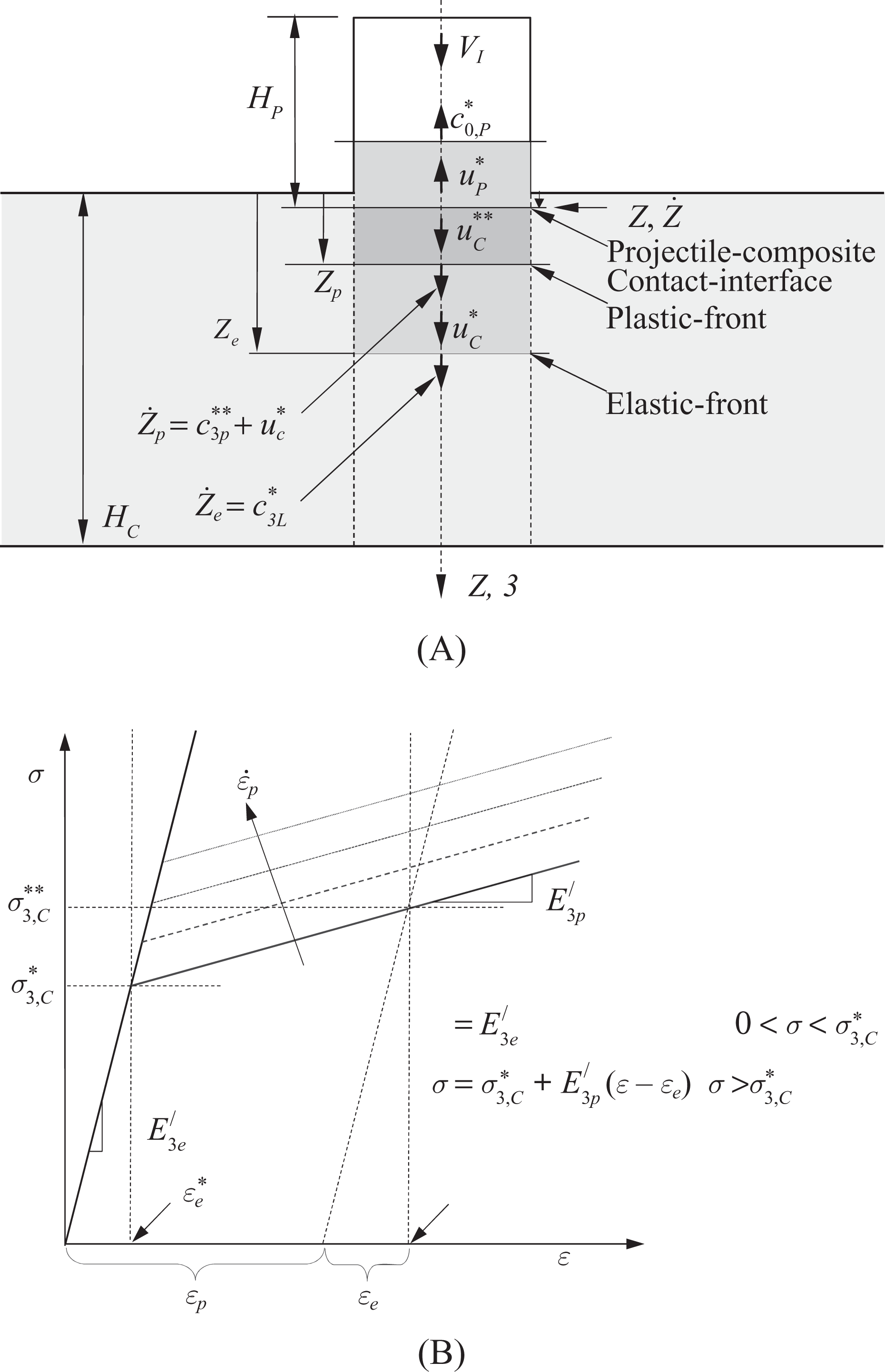
One-dimensional (1D) shock compression model of projectile impact on a composite plate. (A) 1D shock compression model. (B) Compressive engineering stress-strain model for composite under plain strain impact loading.
Similarly, considering the elastic wave propagation in the projectile, an elastic stress wave front will propagate in the projectile with the wave-front speed
Continuity of the particle velocity at the PCCI suggests that the absolute velocity of the elastic zone in the projectile is equal to the particle velocity in the plastic zone of the composite,
50
which is also equal to the velocity of the PCCI,

Considering linear elastic material behavior for the projectile, the stress in the elastic zone of the projectile can be written as

where
Conservation of mass, momentum, and front locations for the elastic and plastic fronts in the composite (Figure 2(a)), and the location of the PCCI can be written as
49
Elastic front conditions
Plastic front conditions
PCCI


The through-thickness strain–density relationships under plain strain loading for elastic and plastic conditions for the composite material can be expressed as
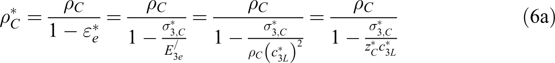
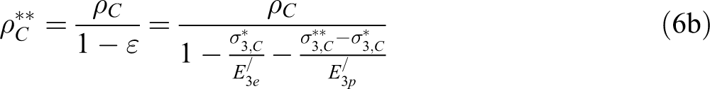
Composite density in the elastic zone given by equation (6a) can also be obtained from the solution of equations (3a) and (3b). However, solutions of equations (4a) and (4b) do not provide equation (6b) for the density of the composite in the plastic zone, rather provides the following solution
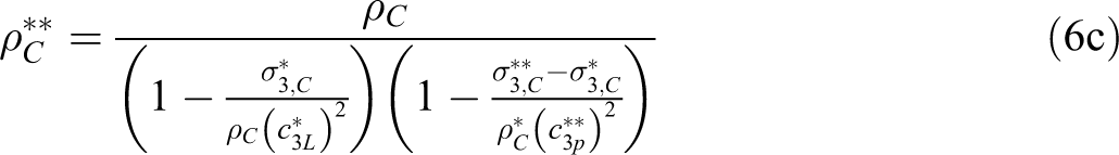
Thus, equating equations (6b) and (6c), one can determine the plastic front velocity with respect to immovable materials as
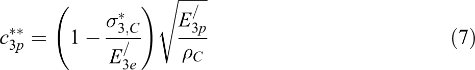
Equation (7) is obtained using the mass, momentum, and strain–density relationships, which was not known a priori. The stress in the elastic zone of the composite laminate is given by equation (3b)

Using equation (8), the particle velocity in the elastic zone of the composite laminate can be expressed as
Stress in the plastic zone of the composite laminate is given by equation (4b), where the particle velocity,

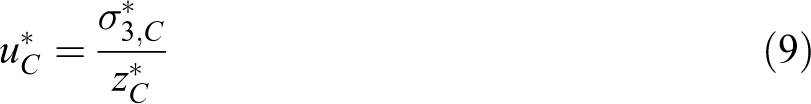
In order to determine

Denoting the impedance of shocked composite by

which leads to
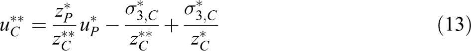
Substituting equations (1) and (8) into equation (13) yields
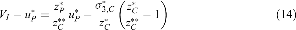
which can be simplified to
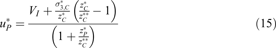
Using equations (1) and (15), one can write
Equation (16) is necessary to calculate the stress of the composite in the plastic zone using equations (10) and (9)
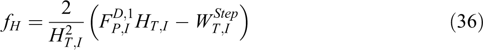
The phase I dynamic PR force on the projectile can be expressed as
Equation (18) is the new 1D shock solution for the dynamic PR force acting on the projectile as a function of impact velocity, elastic–plastic composites properties, and the through-thickness crush strength of the composites.
If the shock stress at the PCCI is less than the plain strain yield stress (
Equations (19) and (20) are the 1D elastic stress wave solutions for 1D impact and are available in literature. 50 Derivation of equations (19) and (20) from fundamental relations are presented in Appendix A for reference.
Equations (20) and (18), respectively, provide the elastic and elastic–plastic solution for the shock stress as a function of the impact velocity of the projectile. Figure 3(A) presents the results for a cylindrical steel projectile impacting a PW S-2 glass/SC15 thick section composite plate (properties are listed in the section on Results and discussion). Two values of plain strain yield stress, that is
Elastic and elastic–plastic solution of shock stress as a function of the impact velocity of the projectile. Plain weave (PW) S-2 Glass/SC15 composite plate, cylindrical steel projectile of diameter,
Stepwise solution procedure
The PR force as a function of impact velocity of the projectile given by equation (18) will remain constant until the compressive elastic stress wave front in the projectile reflects back from the free surface of the noncontact end of the projectile as tensile stress wave and reaches the PCCI. The time required for the elastic stress wave front to reach the free end of the projectile is given by
where


where
Discontinuity between solution steps
At the end of solution step 1 and at time


Momentum

Setting
and solving the mass and momentum equations 31 and 32, we can determine the value of
after which the second solution phase can begin with continuity of stress and displacement at the PCCI. In our stepwise solution for phase I, we will present this time gap between consecutive solution steps.
Linear approximation of phase I elastic–plastic PR force
If the stepwise solution procedure is continued until time

with n additional time discontinuity and one additional partial time step. We can use these step solutions to make a linear approximation of the PR force as a function of projectile displacement

where the second superscript 1 denotes solution step 1. In order to determine the coefficient,
where the total projectile displacement of the projectile can be calculated by

The coefficient
Rate-dependent plain strain yield stress of the composites
In the plain strain elastic–plastic material model for composites presented in Figure 2, the rate dependency of the plain strain yield stress can be modeled using a logarithmic function
47

where


The average plastic strain over time,
and the plastic strain rate by
Since the particle velocities in the elastic and plastic zone of the composite are not known a priori, one can use the quasi-static value of the plain strain yield stress to estimate the particle velocities and then determine the rate-dependent plain strain yield stress using iterative procedures.
Equations (22) to (26) represent the 1D shock compression model of projectile impact on composites during short-time phase I deformation, and equation (32) is a linear approximation of the 1D shock solution. The dynamic effect or the stress wave propagation effect is incorporated in the 1D shock compression model, and the strain rate effect on the through-thickness material properties can be included in the 1D shock compression model using equations (37) and (41). The linear approximation of the phase I 1D shock compression model is combined with the phase II semi empirical quasi-dynamic PR (QD-PR) model to describe the entire penetration event.
Semiempirical (QD-PR) model for phase II ballistic penetration
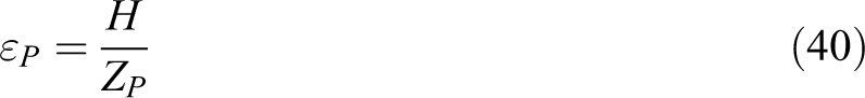
We assume that at the end of phase I shock compression, the material starts to soften and shows tension shear–dominated PR. Since the behavior of phase II penetration is not known a priori, we propose a semiempirical model to estimate that from QS-PR force–displacement data. The QS-PR curve presented in Figure 1 can be rewritten as a function of the location of the PCCI, H, including a DIF as

where
The projectile deceleration as a function of projectile displacement can now be expressed as

The linear approximation of phase I 1D shock compression solution (equation (32)) intersects with the phase II QD-PR curve (equation (42)) at displacement,
The phase I projectile displacement, velocity, acceleration, and PR force can be determined from 1D shock compression model as a function of time up to a time
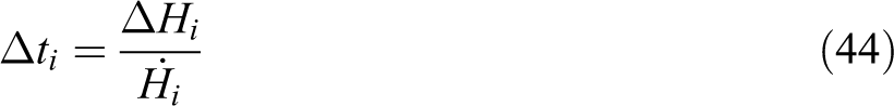
Which then can be used to calculate the time and velocity for the next increment


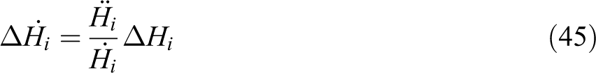
Using the quasi-dynamic PR force as a function of displacement given by equation (42), the acceleration of the projectile as a function of projectile displacement can be determined by equation (43). The time for the projectile as a function of projectile velocity can be determined using equations (44) and (46), and the projectile velocity as a function of projectile deceleration and velocity can be calculated using equations (45) and (47), which completes the phase II solution for projectile displacement, velocity, acceleration, and PR force as a function of time.
The combined theoretical-semi-empirical penetration model of ballistic penetration
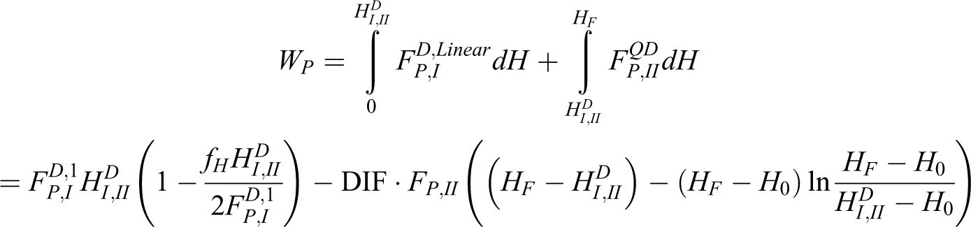
The phase I 1D shock compression model and the phase II QD-PR curve can now be combined to provide the complete solution. The work done by the projectile can be found by integrating the PR force described by equation (32) for phase I, and by equation (42) for phase II with respect to the projectile displacement
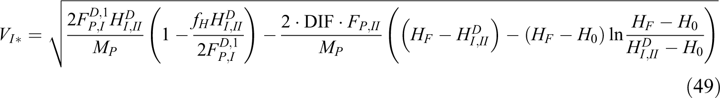
Equating the work done by the projectile to the initial impact kinetic energy (WP = MPVI*
2
/2), the projectile velocity (VI*) required for complete penetration can be estimated
The combination of 1D shock compression model with QD-PM can now be termed as the new theoretical–semiemperical model of ballistic penetration. In this model, the DIF is unknown and should be estimated following the energy balance procedures. If the experimental ballistic limit velocity is known, the DIF can be estimated by equating the ballistic limit energy to the total energy calculated from the combined penetration model

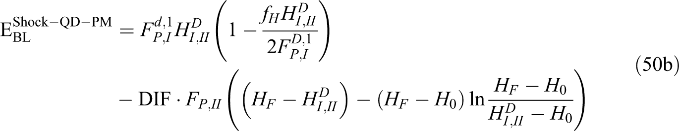
or
Since
Results and discussion
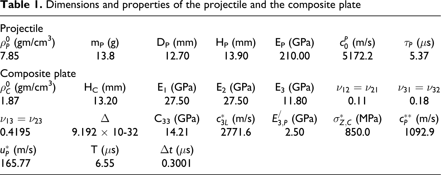
The new theoretical–semiempirical penetration model equations are solved using numerical integration procedures in a MATLAB program. Geometric and mechanical properties of the right circular cylinder projectile and the PW S-2 glass/SC15 composites used in the ballistic experiments of Ref. 44 are used to compute the 1D shock compression model parameters and are presented in Table 1. The plastic modulus of the composite under through-thickness plain strain impact loading condition is estimated from QS through-thickness indentation testing of composite plates of thickness HC = 7.62 mm with right circular cylinder indenters of different diameters (DP = 6.3 mm, 7.9 mm. 9.5 mm, and 11.1 mm). Figure 4 shows the compressive stress as a function of plastic or nonlinear strain, from where the average plane strain yield stress for this model is calculated to be
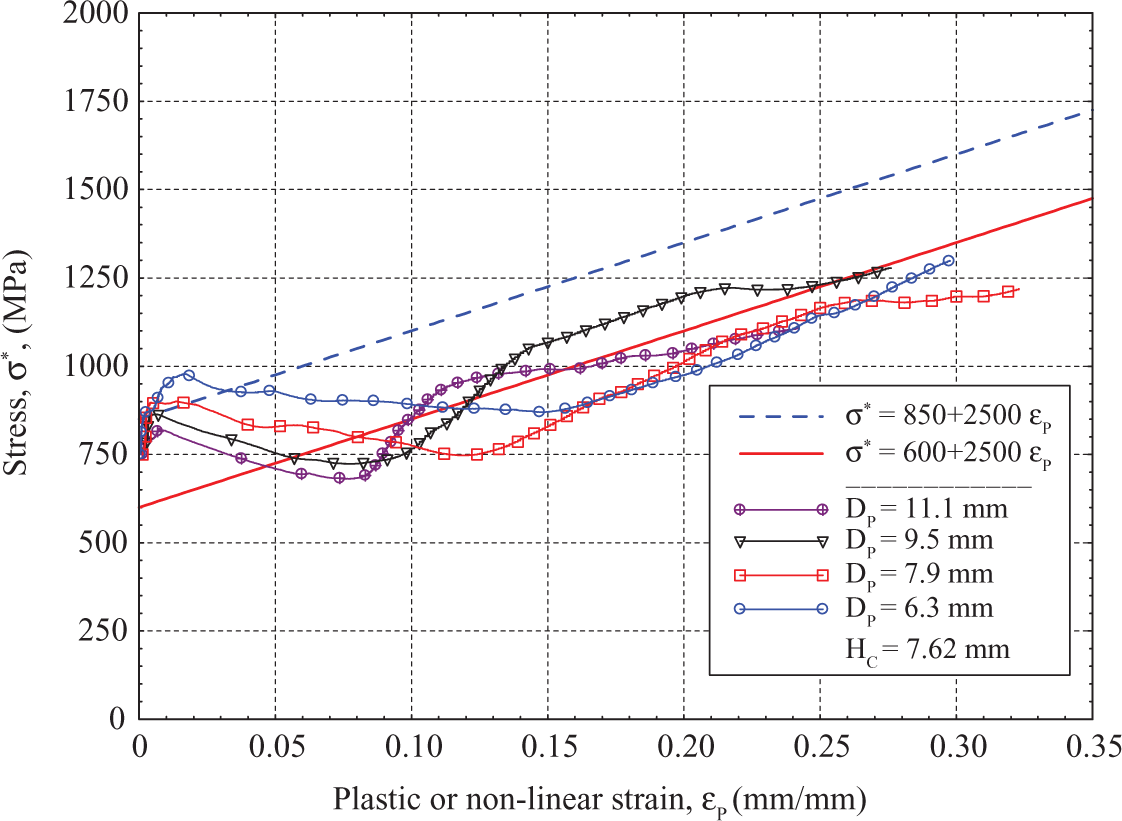
Compressive stress plastic strain behavior of Plain weave (PW) S-2 glass/SC15 composites.
Dimensions and properties of the projectile and the composite plate
Phase I 1D shock-compression model predictions
The particle velocity corresponding to the through-thickness yield stress (
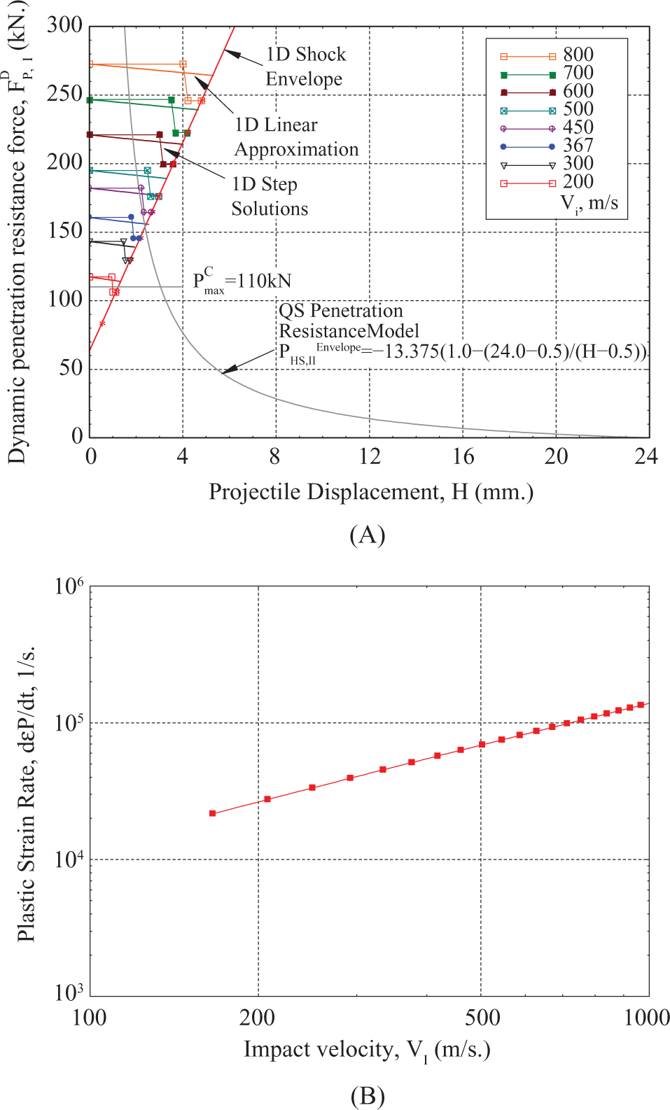
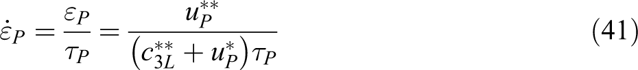
Phase I dynamic penetration resistance force and plastic strain rate. HC = 13.2 mm, τP = 5.37 us, T = 6.55 us. (A) Penetration resistance force. (B) Plastic strain rate.
By connecting the ends of the theoretical contact forces for different impact velocities, a 1D shock envelope can be plotted to differentiate between phase I and phase II penetration behavior. A linear approximation of the stepwise force–displacement solution is determined using equations (32) to (36) and is presented in Figure 5(A) as solid lines without symbols. The plastic strain rate that develops during the first solution step (equation (41)) is linear with impact velocity and is presented in Figure 5(B). If the through-thickness yield stress and plastic modulus of composites under dynamic plain strain loading can be determined as a function of plastic strain rate from experiments, the present 1D shock model will allow one to consider the effect of strain rate as well.
Combined shock-QS-PR model predictions
The QS-PR curve developed from QS-PST experiments (Figure 1) can be combined with the phase I shock compression model to predict the projectile dynamics and is presented in Figure 6. The shock-QS-PR model can predict the projectile velocity, displacement, and time at and above the ballistic limit velocity of the composite plate. The shock-QS-PR model also provides an analytical expression to calculate the approximate VBL (equation (49)), value of which is found to be
Shock quasi-static penetration resistance (QS-PR) model input and prediction. (A) Penetration resistance force as a function of projectile displacement. (B) Projectile velocity as a function of time.
The combined theoretical–semiempirical (shock Quasi-Dynamic) penetration model predictions
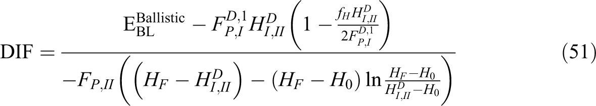
Dynamic effects in the phase II penetration are considered by introducing the DIF in equation (42), the value of which can be estimated using equation (51). The value of DIF which predicts accurate VBL based on the energy balance equation (51) is estimated to be 1.10 and its effect on projectile dynamics and on PR is investigated next. The shock QD-PM calculations are compared with the LS-Dyna FEA solutions (validated with experimental results) presented in Ref. 46. Figure 7(A) shows the shock QD-PM input PR force as a function of projectile displacement for DIF = 1.00 and 1.10 at an impact velocity VI = 367 m/s. The LS-Dyna FEA prediction of PR force 46 at VI = 360 m/s showed rebound of the projectile, while at VI = 380 m/s showed complete penetration; however, the force–displacement at both the impact velocities appeared to have a small difference up to projectile displacement H = 15 mm. Similarly, the difference in the shock QD-PM force–displacement input for DIF = 1.00 and DIF = 1.10 is also small, however, appears to be the average of the LS-Dyna predictions. A small difference in force–displacement may appear as a large difference in velocity time response as shown in Figure 7(B). The LS-Dyna prediction clearly shows the rebound of the projectile at VI = 360 m/s with VR = −26.7 m/s, and complete penetration at VI = 380 m/s with VR = 38.3 m/s. Ideally, at ballistic limit velocity VBL = 367 m/s, the residual velocity should be zero, VR = 0.00 m/s, however, the shock QD-PM predicted VR = 0.08 m/s at time t = 871 μs (not shown in Figure 7(B)) for DIF = 1.10, and predicted VR = 84.6 m/s at time t = 185 μs for DIF = 1.00.
Validation of shock quasi-dynamic (QD) penetration model with LS-Dyna analyses. (A) Force vs. displacement. (B) Velocity as a function of time.
Clearly, the new theoretical–semi empirical penetration model (shock QD-PM) can predict the ballistic limit velocity, VBL, and the time history of the projectile velocity accurately with the correct choice of DIF, which is a constant. However, prediction of projectile dynamics above VBL will require theoretical modeling of phase II penetration and will be addressed elsewhere.
Summary and conclusions
Impact and penetration dynamics of a cylindrical projectile on a thick section composite laminate is presented. A theoretical 1D shock compression model has been developed for short-time phase I shock compression to determine the PR force on the projectile and the projectile dynamics. A rate-sensitive elastic–plastic material behavior is used to model the through-thickness plastic shock and elastic stress wave propagation upon impact. Conservation of mass and momentum at the wave fronts are used to calculate the stress and particle velocities in the shock/plastic and elastic zones to determine the PR force. For the 13.2-mm-thick S-2 Glass/SC15 composite laminate under impact of a 13.8-g cylindrical projectile (DP = 12.7 mm) at ballistic limit velocity
The phase I theoretical 1D shock compression solution is combined with the phase II QS-PR curve obtained from the QS-PST experimental methodologies, and a ballistic limit velocity of
Highlights
A theoretical formulation based on 1D-shock theory of a RCC projectile on a finite thickness composite plate is presented.
The plastic wave-front velocity in the composite is determined using mass, momentum, and strain-density relationships (equation (7)). A new finding.
A new 1D-shock solution for the dynamic penetration resistance force (equation (18)) acting on the projectile is obtained which is a function of impact velocity of the projectile, the elastic-plastic impedances, and the through-thickness crush strength of the composites.
The new 1D-Shock stepwise solution is discontinuous between solution steps. Duration of this discontinuity is quantified solving the mass and momentum equations (equation (30)) and is necessary for multiple solution steps in very thick composites.
A dynamic increase factor, DIF, is added to a quasi-static penetration resistance (QS-PR) curve to formulate the Phase II Quasi-Dynamic Penetration Resistance (QD-PR) model. A numerical integration scheme is used to calculate the incremental projectile velocity as a function of time and displacement.
The theoretical 1D Shock-Compression model is combined with the semi-empirical QD-PR model as the new Theoretical-Semi-Empirical or Shock-Quasi-Dynamic Penetration model to predict the ballistic limit of thick-section composites and the projectile dynamics at the ballistic limit. Good correlations with previous FEA results are obtained.
Footnotes
Appendix A
Appendix B
Authors’ Note
The views and conclusions contained in this document are those of the authors and should not be interpreted as representing the official policies, either expressed or implied, of the Army Research Laboratory or the U.S. Government. The U.S. Government is authorized to reproduce and distribute reprints for government purposes notwithstanding any copyright notation hereon.
Funding
Research was sponsored by the Army Research Laboratory and was accomplished under Cooperative Agreement Number W911NF-06-2-011.