
Abstract
Three dimensional (3D) spacer fabrics are constructed from two dimensional (2D) woven fabrics connected by 2D woven crosslink fabrics using thermoplastic high performance hybrid yarns. Spacer fabrics present great potential in the efficient production of fiber reinforced plastic composites with adjustable mechanical properties targeted for specific applications in Lightweight engineering. The structure of the weave and the stresses placed on the fibers during the weaving process impact the mechanical properties of the finished composite. This study shows that the mechanical properties can be significantly controlled and adjusted by pattern development of the individual 2D composite structures from the 3D spacer fabric preforms constructed of orthogonal multi-layer weaves (non-crimped fiber arrangement and a gentle weaving process). Electrically conductive fibers are woven directly into various layers of the 2D woven fabrics and are therefore successfully integrated during production. This forms the basis for function integration in the composite. The weaving technology ensures a reliable contact of the conductive fibers allowing sensor networks to be integrated into the fabric for online monitoring of the fiber reinforced plastic composite component.
Keywords
Introduction
Fiber Reinforced Plastics (FRP) are increasingly being used in Lightweight engineering where performance and energy efficiency play important roles. Along with carbon fibers (CF), glass fibers (GF) and aramid fibers (AR) are also used in the production of FRP. 1 In the aerospace industry, FRPs based on carbon fibers are already prevalent in current aircraft, such as the AIRBUS A380 where 22% of the components are carbon based FRPs and in the BOEING 787 Dreamliner where over 50% of the components are made of carbon FRPs. These figures illustrate the progressive increase in the use of FRPs in the aircraft industry.2,3 Other important sectors where FRPs are prevalent include the astronautics industry, wind power engineering, the automotive industry, naval architecture and complex machinery and production systems.
Due to their excellent mechanical properties, such as stiffness, strength and dimensional stability, weaves lend themselves to numerous applications in fiber reinforced polymer engineering. The weaving technology enables high performance fibers to be used for high density woven structures with load-oriented fiber positioning. Innovative textile preforms as double-walled shell structures (i.e. 3D spacer fabrics) possess high stiffness and low mass. Such preforms have been developed that are manufactured in a one-step integrated production process which requires no additional processing steps such as sewing or glueing.4–8
One of the foci of the Collaborative Research Centre 9 in addition to the technology development and its implementation, is also the improvement of composites’ mechanical properties from 3D woven spacer fabrics for complex lightweight applications. Additionally, weaving technology is to be developed for creating reliable contacts and aligning electrically conductive yarns for the online monitoring of customized 3D FRPs. A further challenge is allowing for flexible 3D spacer fabric geometries, such as variation in surface structure, variable crosslink spacing and double curved surfaces (outer layers) while simultaneously reducing yarn damage during processing and improving the fabric's stiffness. 10
Manufacturing 3D Woven Spacer Fabrics
In contrast to the conventional spacer fabrics (pile weaves) connected by additional pile yarns, 3D woven spacer fabrics are constructed of woven outer layers connected by crosslink fabrics. This allows thermoplastic based 3D preforms using GF/PP hybrid yarns to be manufactured in just one process step and possess good mechanical properties such as compressive, tensile, flexural strength and impact resistance.4–7 In comparison to thermoset FRP, thermoplastic FRPs provide numerous advantages in regards to material storage, recycling and require lower temperatures and shorter cycle times during the consolidation process.11,12 Figure 1 illustrates the structure and composite form of a conventional pile weave and an innovative 3D woven spacer fabric.
Conventional pile weave (a), a 3D-woven spacer fabric (b) and their composites (c) and (d).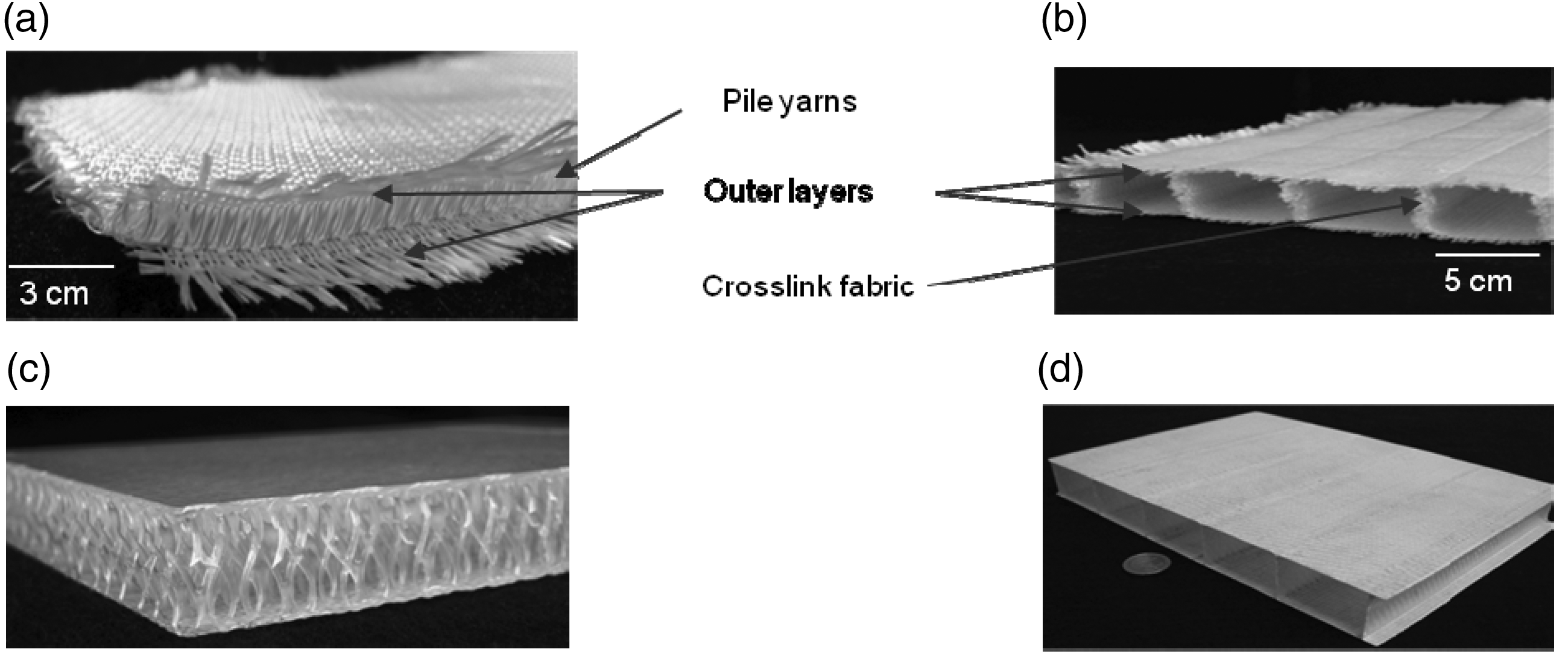
The developed technology was used to create spacer fabrics with two or more woven surfaces for the manufacture of 3D spacer fabric structures. The technology was implemented on a modified double rapier weaving machine. To produce the crosslinks, a terry weaving mechanism in addition to a fabric storage mechanism and a warp pull-back mechanism are necessary. To manufacture 3D spacer fabrics, two warp yarn systems are required. The warp yarns from one system together with the weft yarns create the outer layers of the spacer fabric. The second warp yarn system is weaved into the outer layers to build the crosslinks. Initially, the outer layer fabrics are woven with both warp yarn systems. For the crosslinks, only the warps from the second warp system are used in which the warps from the outer layers create the floats. In the middle of the crosslinks, the warp yarns change their position. The second warp yarn system from the lower crosslink fabric is carried over to the upper crosslink fabric and vice versa. Once the desired crosslink length is reached, the two warp yarn systems are incorporated into the respective outer layer fabric by means of several weft yarns. Subsequently, the temporarily stored fabric length, which corresponds to the height of the desired crosslink and the length of the warp floats, is set free by the terry weaving mechanism. The warp floats are then pulled back in the direction of the warp beam. When the beat-up of the last weft yarn of the formed crosslink occurs, the reed pushes the woven crosslink between the outer layers as a pleat. The terry weaving mechanism, in combination with the warp pull-back, enable the flexible formation of integrated woven crosslinks with variable spacing. The weaving machine was mechanically altered to accommodate this purpose. In addition to the terry weaving mechanism and the warp pull-back, a stretched roller take-up with automated supporting bars was developed and built onto the machine. These developments are indispensible for gentle processing and a reproducible production of 3D spacer fabrics.4,5,7 Figure 2 diagrams the production technique (a) and the machine modifications (b) required to manufacture 3D spacer fabrics.
Production technique (a) and machinery modifications (b) for manufacturing of 3D woven spacer fabrics.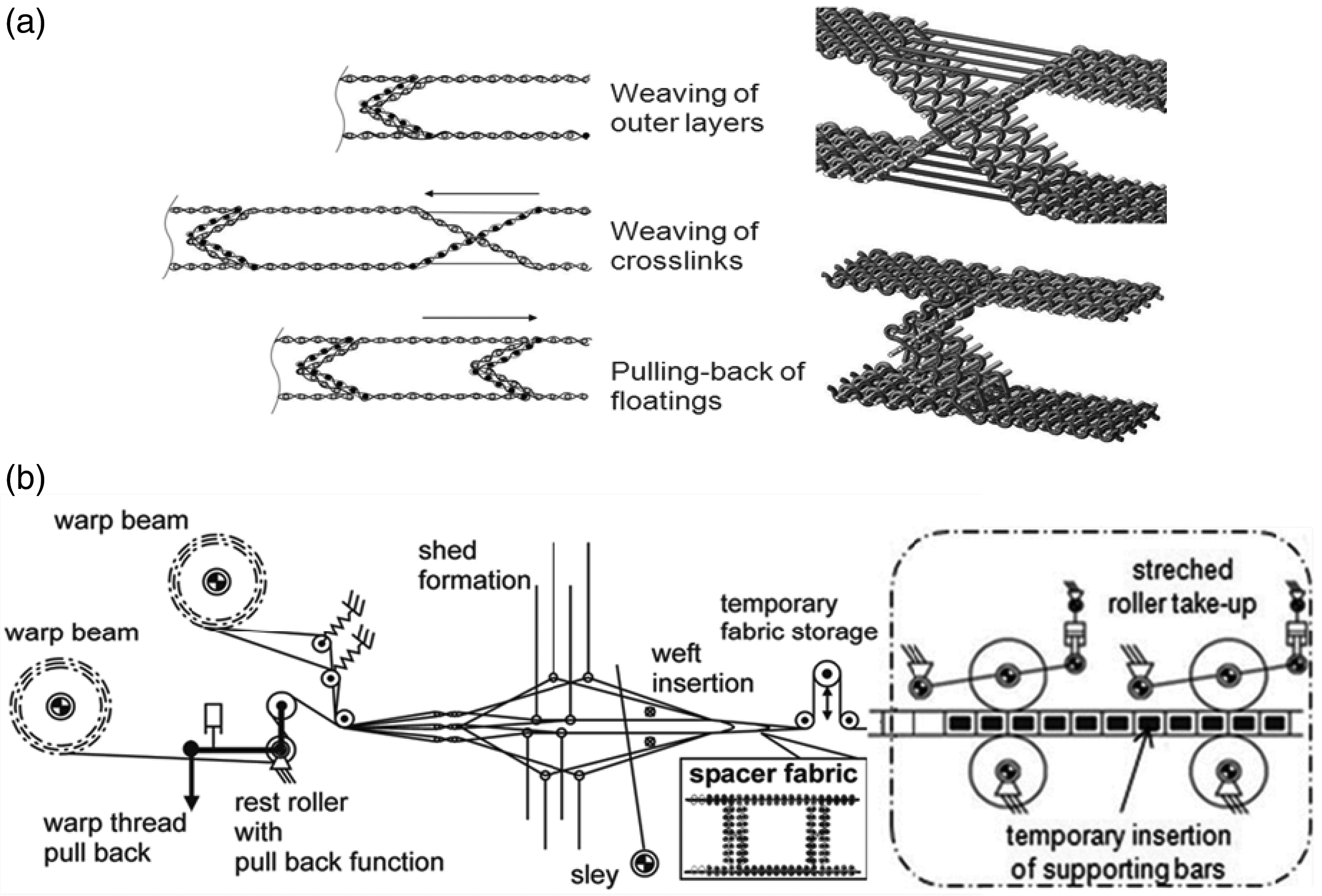
3D Woven Spacer Fabrics with Function Integration
The nature of FRPs often means they are inevitably exposed to complex multi-axial stresses in engineering systems. Extended or excessive stress and defective bonds can lead to invisible damage to the component, such as delamination, fiber breakage or cracks in the matrix material. This results in a localized reduction in structural stiffness and strength, which in turn can cause an unforeseeable and sudden failure of the component. This is why it is imperative to monitor, by means of integrated sensors, those components that are crucial to the security and intactness of the system. Sensor monitoring allows for constant and continuous registering of the stresses working on the component, which enables early detection and evaluation of structural damage while in operation. Damage can then be repaired at an early stage and thus sudden failure of the component can be successfully avoided. 13 Such integrated sensors for FRPs are already developed and tested.14–18 Information collected according to problem specific criteria and gathered from all the monitoring ports is forwarded via bus units to an evaluation unit. Together with all information collected from the monitoring ports, the localized stress points can be evaluated and analyzed. This type of information processing requires a network of sensors that includes each individual monitoring port and is connected per bus structure.
To date, the integration of network structures in finished FRP components is associated with considerable technical effort and time investment. Therefore, integrating the network structure during the production process proves to be more effective and protects the system against undesirable environmental factors such as humidity, chemicals and mechanical stresses. 17 The weaving technology offers favorable conditions for designing custom networks tailored to specific tasks. By routing conductor paths and making insert preparations by modifying the fabric structure with various localized binding techniques, reliable contacts for the conductors can be realized in just one production step. Further advantages with woven connections include fewer conductor defects or disturbances.
Experimental
2D woven fabrics make up the outer layers and the crosslinks of the 3D woven spacer fabrics, also defined as 3D textile preforms. The structural, mechanical properties of the 3D preform and the integration of the conductive paths depend heavily on the structure of the 2D woven fabric. Based on this, tests to determine the mechanical and electrical properties were conducted on 2D composites made of 2D woven fabrics produced on a double rapier weaving machine. The electrical properties of the conductive paths and the interconnections formed with the weaving technology were analyzed. These tests allow for a reliable prediction of the mechanical and electrical behavior of 3D spacer fabric composites.
2D Woven Fabrics from GF/PP High Performance Hybrid Yarns
Within the framework of this study, the hybrid yarn (416 tex) consists of GF used as a high performance yarn (300 tex, P-D GLASSEIDEN GmbH, Germany) and a modified polypropylene fiber (PP) used as a thermoplastic (3x32 tex “Prolen H”, CHEMOSVIT FIBROCHEM a.s., Slovakia). The commingled yarn was manufactured with Air texturizing technology and a fiber volume ratio of 52:48, optimal for lightweight engineering applications.9,19 The GF/PP hybrid yarns were processed on a double rapier weaving machine VTR-23 (N.V. MICHEL VAN DE WIELE, Belgium) with a working width of one meter and a warp thread density of 200 threads per 10 cm per outer layer to form multi-layer woven spacer fabrics. The machine was equipped with a jacquard unit and a weft thread changer to accommodate the integration of electrically conductive thread directly into the fabric structure, as well as to create sensor networks and prepare the fabric for inserts during the weaving process. The multi-layer fabric is comprised of non-crimped GF/PP hybrid yarns, connected with PP binding yarns. This newly developed weaving technology processes the GF/PP hybrid yarn in its stretched form without crimp, which guarantees optimal use of the hybrid yarns fiber substance strength ultimately leading to an improvement in the mechanical properties of the composite (i.e. tensile, compressive and flexural strength). Figure 3 shows two different woven structures used for the outer layers and crosslink of the 3D spacer fabric (a) woven CW with yarn crimp, and (b) an advanced multi-layer fabric without yarn crimp (woven NCW).
Weave structure (CW) with yarn crimp (a) and (NCW) without yarn crimp (b).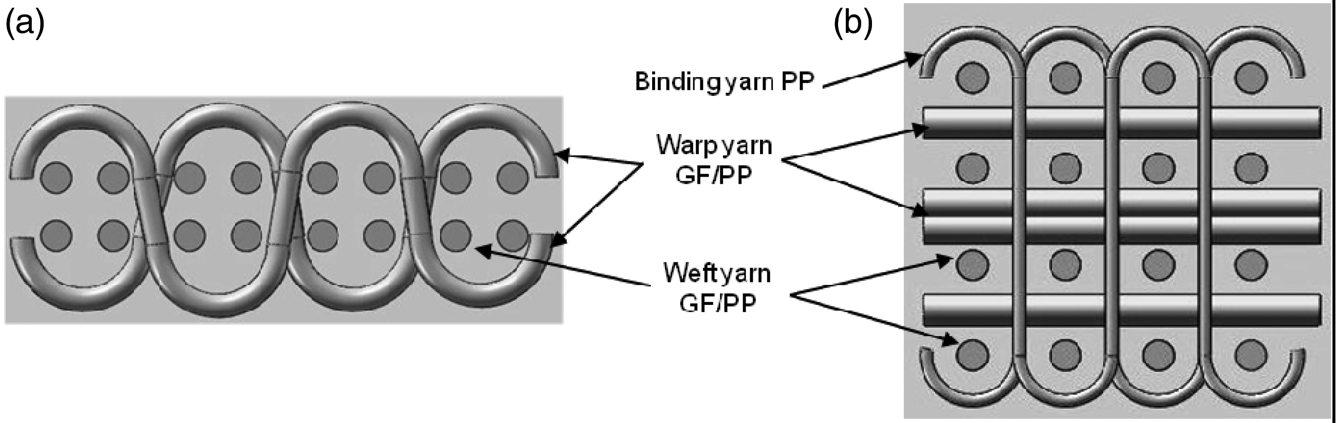
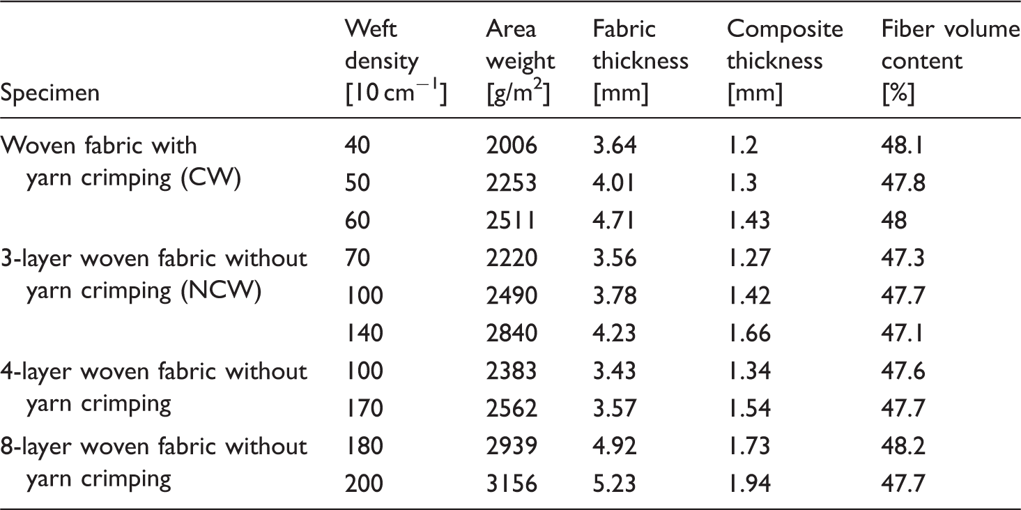
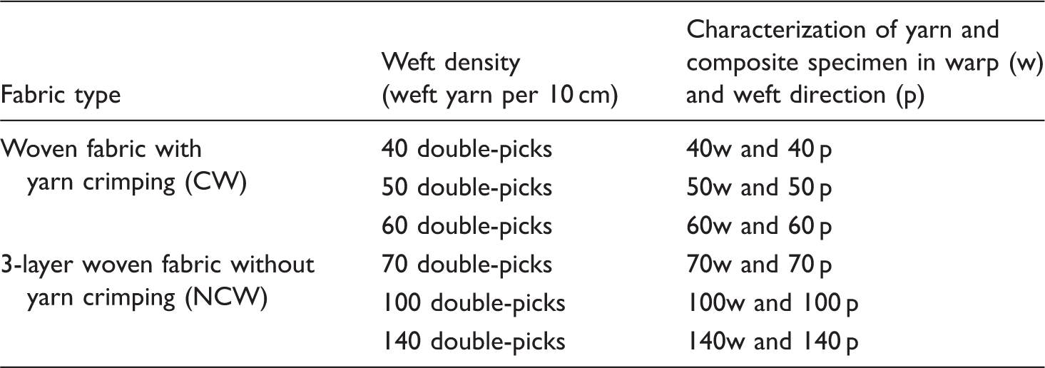
Parameters of the different fabrics in textile and composite forms.
2D Woven Fabrics with Integrated Different Electrical Conductor Threads
Carbon threads, 67 tex, and cooper wires with a radius of 0.2 mm were used as electrical conductors and integrated in the warp and weft directions. Variations in the conductive path spacing in the fabric were regulated by changes in the weft density and by integrating conductive threads into the individual fabric layers throughout the cross-section of the preform. Contacts were created using developed weaving techniques to cross the conductive threads in the warp and weft directions. Different interconnections, as single and double crossing, with and without a change in layers were developed to realize increased contact stability in the conductive yarns.
Figure 4 illustrates the various conductive thread interconnections produced:
one warp and one weft thread without layer change, single crossing. one warp and one weft thread with layer change, single crossing. two warp and two weft threads in a plain weave without layer change, double crossing. two warp and two weft threads in a plain weave with layer change, double crossing.
To determine the contact stability, the contact resistance was analyzed at the crossing points.
Different woven interconnections with carbon fibers as conducting threads in cross section of fabric structures and in surface of composites.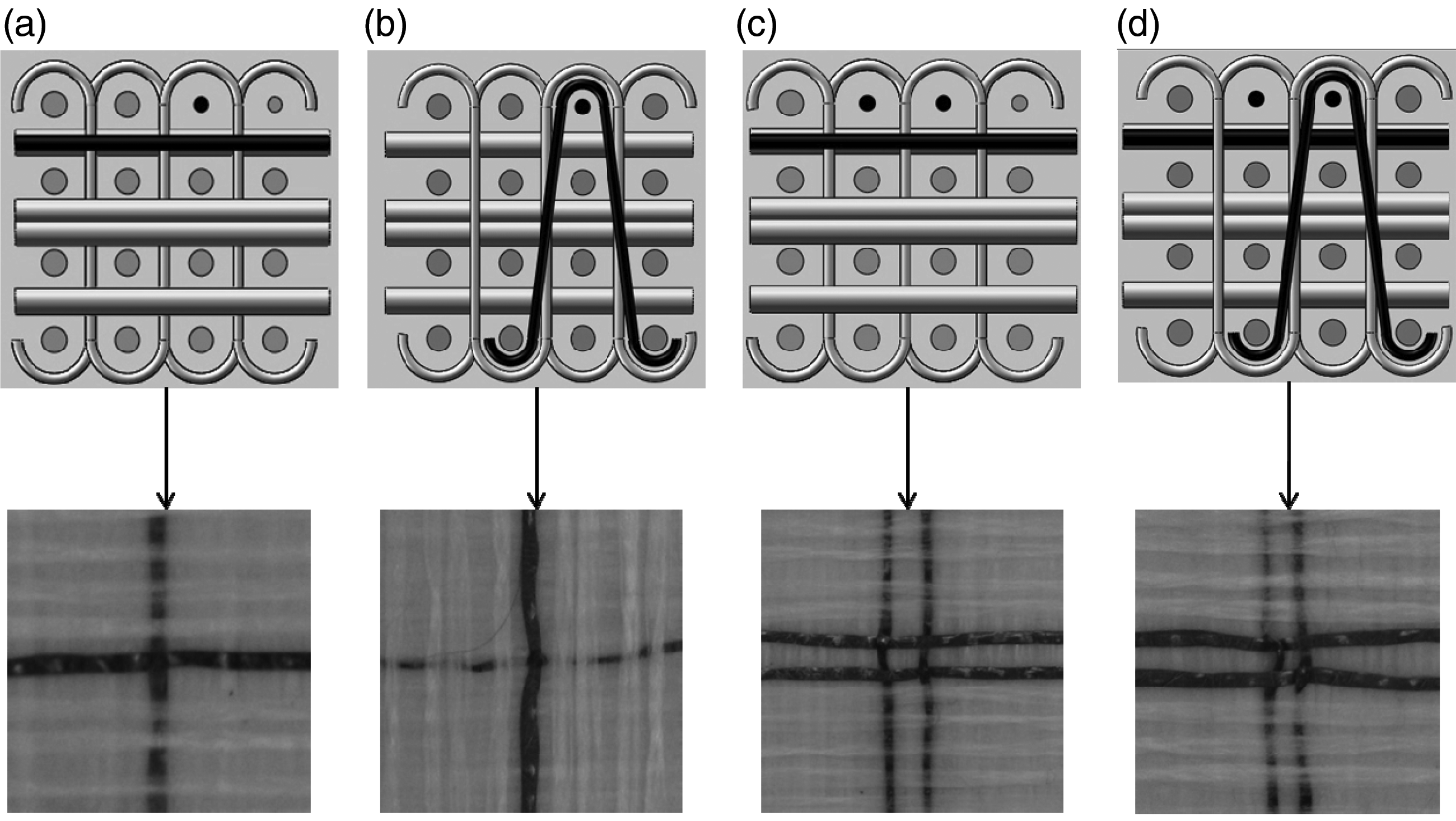
Tensile Force Testing of GF/PP High Performance Hybrid Yarns
The fabric formation components necessary for the weaving process place various stresses on the GF/PP hybrid yarns (416 tex). The stresses placed on the hybrid yarns during processing are directly influenced by the 3D spacer fabric geometry. Therefore, it is necessary to first analyze the thread damage which occurs during production. To analyze the thread damage, individual yarns from the CW (with yarn crimp) and the 3-layer NCW fabrics (i.e. with three warp and four weft thread layers without yarn crimp) in various weft densities were carefully removed to avoid additional thread damage. Subsequently, the removed threads and threads from the original spool (used as a reference) were tested for tensile force on a Zwick Z100 Tensile Testing Machine (ZWICK GmbH & Co. KG, Germany) according to the DIN EN ISO 2062. The decrease in the tensile force of the yarn (L) is recorded as a percent. The decrease (L) was calculated with the following equation, where (Fr) is the tensile force of the reference yarn from the spool and (Fw) is the tensile force from the removed yarn after the weaving process:

Parameters of the yarn and composite specimens from different fabrics.
Measurement of Mechanical Properties of 2D Composites
Mechanical tests for tensile strength, compressive strength, flexural strength and impact behavior were conducted on 2D composite sheets as preliminary investigation for 3D spacer fabrics made from CW and 3-layer NCW in various weft densities. 2D composite sheets were consolidated in a laboratory hot press Collin P300 PV (DR. COLLIN GmbH, Germany). The CW and 3-layer NCW fabrics were individually placed in the press at room temperature. The pressure was then increased to nine bars. To thermally activate the PP, the temperature was increased at intervals of 10°C per minute until the pre-set temperature of 221°C was reached. After six minutes, the pressure was increased to 52 bars and held at a constant temperature for ten minutes. Subsequently, the consolidated composite sheet was then cooled to room temperature under constant pressure.
The tensile, flexural and compressive strength tests on the 2D composite sheets were performed using a Tensile Testing Machine Zwick Z100 (ZWICK GmbH & Co. KG, Germany) according to DIN EN ISO 527-4, DIN EN ISO 14125 (four point bending test) and DIN EN ISO 14126 (ASTM D 3410/A CELANESE type). Tests were conducted with a cross beam speed of one millimeter per minute. The impact test was carried out with the help of a pendulum arm-type impact tester, which works on the principle of the Charpy Impact Test. Standard methods of sampling and testing were applied as stated in the ISO 179-2.
Measurement of the Electrical Properties on 2D Composites
The main electrical parameter of an interconnection is its line resistance. Especially for power supply lines, the line resistance should be as low as possible to avoid voltage drops along the lines. The line resistance is the sum of the resistances of the electrical conducting threads that form the interconnection and the connection resistance at each of the crossing points. The resistance along the electrical conducting threads can only be minimized by keeping the thread lengths short. However, the connection resistance can be influenced by the design of the thread crossings (see Figure 4).
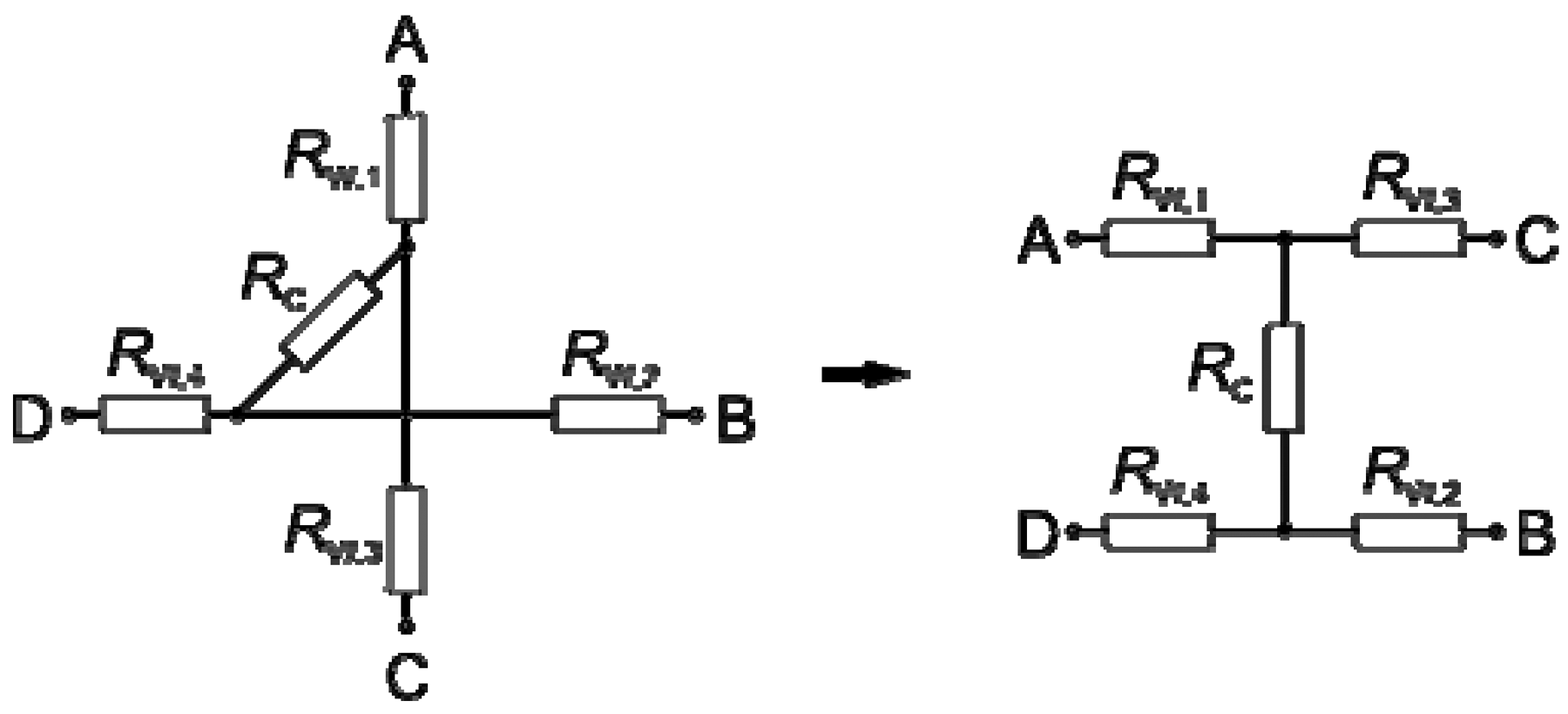
The measurement of the connection resistance was deduced after the consolidation of the composite specimens. A direct measurement of the contact resistance is not feasible as the resistance from the end of the thread to the thread crossings is very large compared to the contact resistance at the crossing points. The measurement of the contact resistance is therefore evaluated by using a differential measurement as described below to eliminate the influence of the resistances of the conducting threads RW on the measurement accuracy. To determine the contact resistance, RC, both the resistance of each thread, RAC, RBD, and the resistance between the thread ends, RAB, RCD, were measured. Utilizing the network model in Figure 5, the measured resistances can be expressed as sums of the resistances between the thread ends and the thread crossing, RW, and the contact resistance of the thread crossing, RC:
Electrical network model of the manufactured specimens (RW resistance between outer contact end and thread crossing, RC contact resistance of the thread crossing).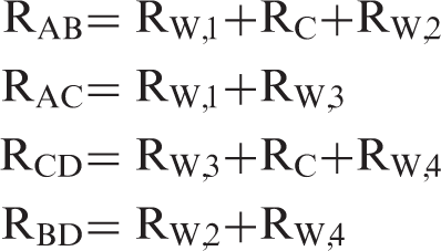
The contact resistance is then calculated by:

Measured connection resistances (mean values and standard deviations).
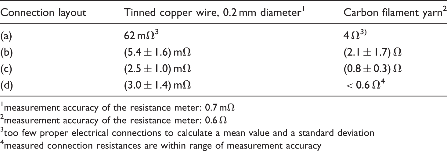
measurement accuracy of the resistance meter: 0.7 mΩ
measurement accuracy of the resistance meter: 0.6 Ω
too few proper electrical connections to calculate a mean value and a standard deviation
measured connection resistances are within range of measurement accuracy
To create an electrical contact, the carbon filament yarn was wound with tinned copper wire (diameter 0.2 mm). This contacting technology offers reliable electrical contacts with minimum contact resistance between the copper wire and the carbon filament yarn. 17 As a measure of reproducibility, the standard deviations of the measured connection resistances are shown in Table 3. Because four conducting threads in parallel were used as one interconnection line for the connection layout (d), the connection resistance was consequently decreased to conform to the measurement accuracy of the used measuring devices. Therefore, only the upper limits of the connection resistance could be specified for those specimens. For the connection layout (a) only one of the specimens showed an electrical connection between the crossing threads (both for the tinned copper wire and the carbon filament yarn). It is assumed that polypropylene crept between the threads during the consolidation of the composite which electrically disconnected the threads. For the connection layouts (b) to (d) all connections were electrically conducting.
Results & discussion
Tensile Test of the used GF/PP Hybrid Yarn from Woven Fabrics
The loss in the 416 tex GF/PP hybrid yarn's tensile strength was greatly influenced by yarn arrangement in the fabric and the weft density. The tensile force measured for the reference yarn was 75 N. Figure 6(a) depicts the stress-strain curves for the yarn removed from the CW specimen in various weft densities in both the warp (w) and weft (p) directions. Figure 6(b) illustrates the resulting loss in the yarn's tensile force caused by the weaving process. With increased weft density, the loss of the tensile force increases by 25% to 48% in the warp direction and remains constant at approx. 35% in the weft direction. The stress-strain curves of the yarns removed from the 3-layer NCW (Figure 6(c)) show, in comparison to those yarns removed from the CW specimen, a significantly higher tensile strength and extensibility.
Effects of weft density and weaving process on tensile force of 416 tex GF/PP hybrid yarns from fabric (CW) with yarn crimp (a and b) and (NCW) 3-layer fabric without yarn crimp (c and d).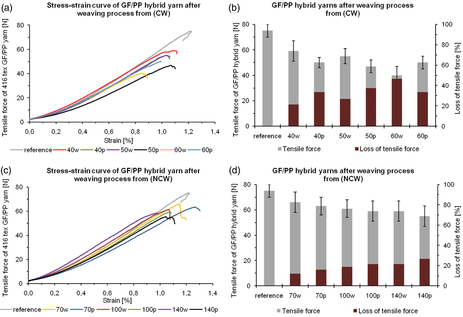
Figure 6(d) shows a loss of the tensile force in the warp and weft, e.g. for 140w 21% and for 140 p only 26%.
During the weaving process of the NCW fabrics, the GF/PP hybrid yarns are processed gently resulting in minimal damage occurring during production, despite the required increase in weft density to increase the fabric's stiffness for an improved composite loading capacity. The stretched thread arrangement of the high performance fibers (GF) during weaving and the overall reduction in thread damage during the production of the NCW lead to a superior utilization of the mechanical properties of the GF/PP composite.
Mechanical Properties of 2D Woven Composites
The glass fiber volume content of the 2D composites made from GF/PP hybrid yarns (416 tex) is approximately 48% (see Table 1). The mechanical properties of the hybrid yarns implemented and their arrangement in the fabric geometry influence the composites’ mechanical properties, e.g. tensile strength, compressive strength, flexural strength and impact behavior (Figures 7 to 10). A unidirectional composite (UD) serves as a reference specimen (one layer of 416 tex GF/PP hybrid yarn, loaded in thread direction) to compare the measured values.
Effects of fabric structure with different weft density on tensile strength and tensile modulus of composites.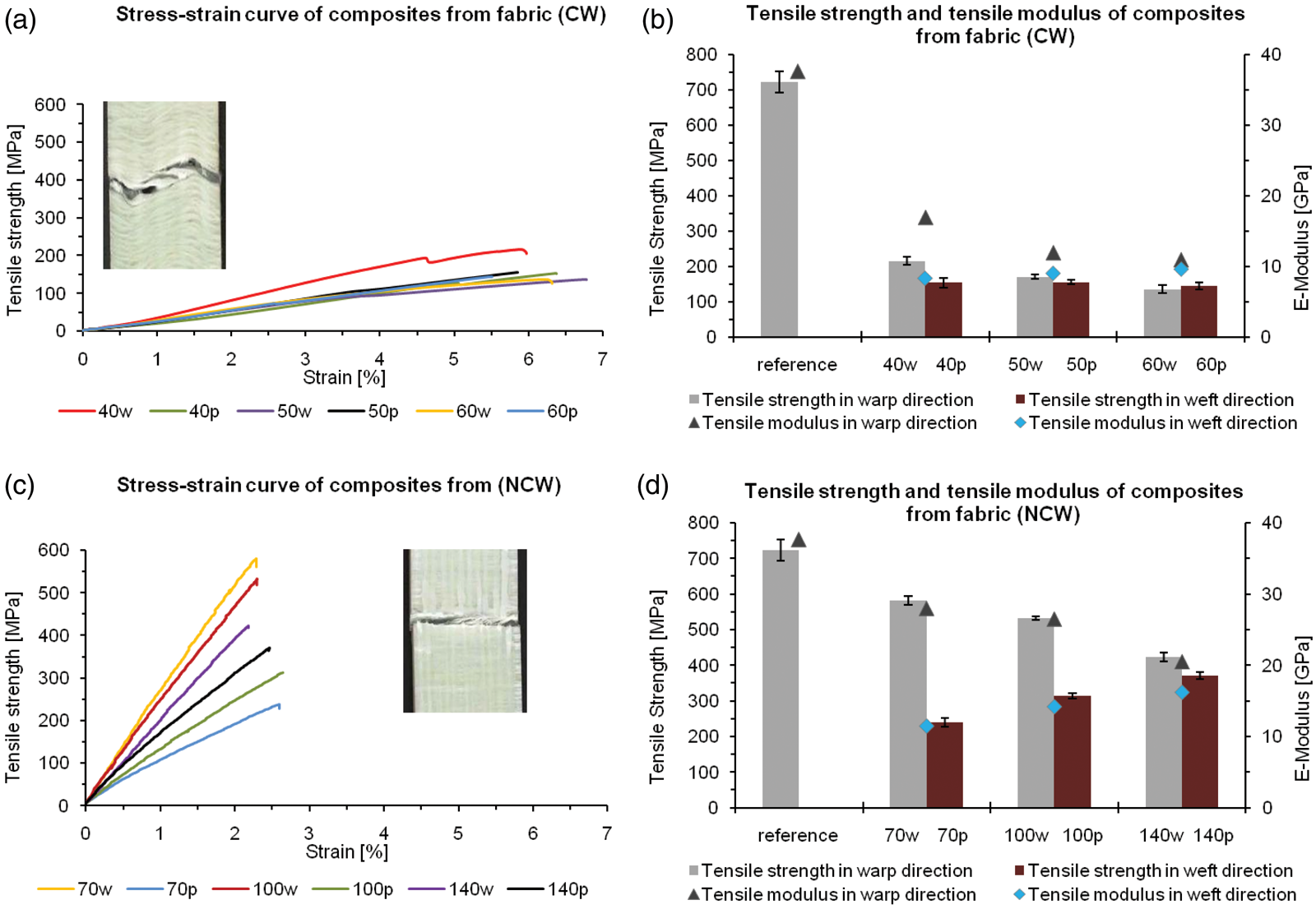
Tensile Properties
The tensile strength of the UD composite is 722 MPa and the E-modulus is 37.7 GPa. The tensile strength and the E-modulus for the CW composites are determined by the fabric structure and are higher in the warp direction than in the weft direction. Both also decrease with increased weft density, while the E-modulus remains constant in the weft direction. A maximum of 215 MPa and 17 GPa in the warp direction and 155 MPa and 9.6 GPa in the weft direction (Figure 7(a) and (b)), were measured respectively for the tensile strength and the E-modulus. The low measured values can be explained as the result of damage to the yarn during the weaving process (decrease in tensile strength) and the yarn undulation inherent to the fabric structure (see Figure 3a). These factors result in a composite extensibility of up to 7%. The composites from the 3-layer NCW show significantly higher measurements in both directions as compared to the CW (Figure 7(c) and (d)). In the warp direction, the tensile strength yields a maximum of 581 MPa and as the weft density increases, the tensile strength diminishes to 423 MPa. In the weft direction, the measured values increase from 239 MPa to 370 MPa with increased weft density. The higher weft density leads to smaller matrix rich regions in the weft direction of the composite, which improves the tensile behavior. The measured E-modulus follows a similar pattern. The maximum value in the warp direction was 28 GPa and 16 GPa in the weft direction. It can be surmised that the stretched threads in the fabric structure of the NCW account for the significantly higher tensile strength and higher measured
E-modulus values, as well as a reduction in composite stretching reaching 2.6%, see Figure 7, (c) as compared to (a)).
Flexural Properties
The diagrams (b) and (d) in Figure 8 show that the composites made from the
Effects of fabric structure with different weft density on flexural strength and flexural modulus of composites.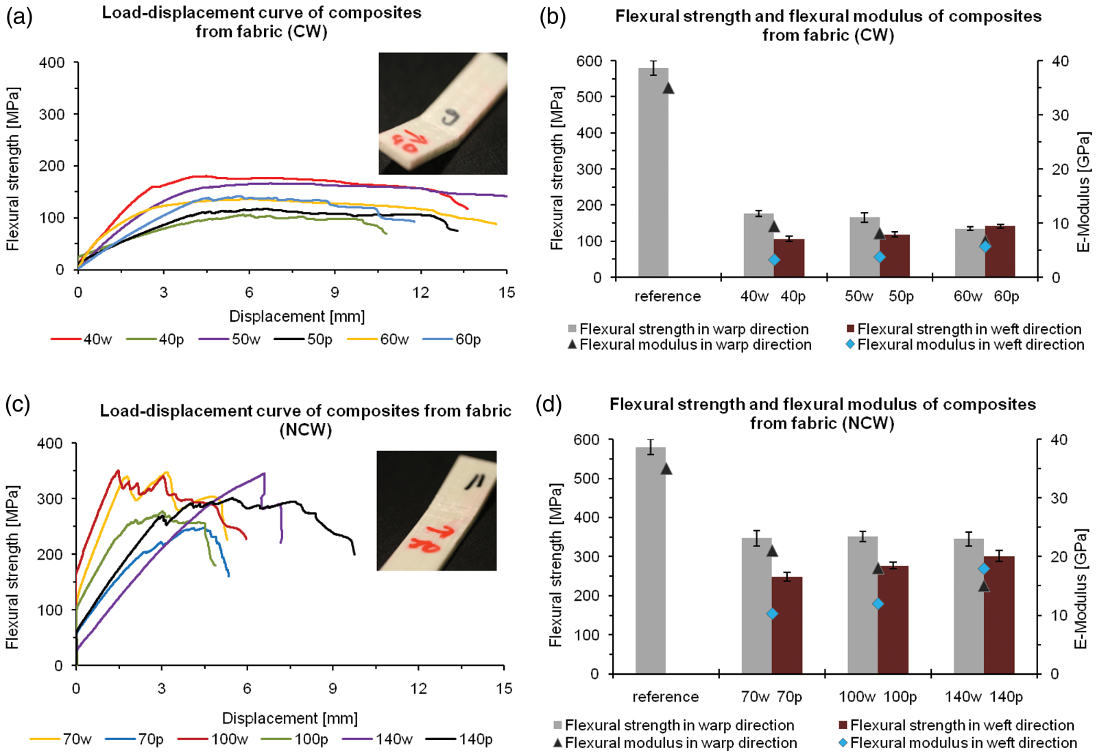
Compressive Properties
The compressive behavior of composites made from CW and 3-layer NCW is illustrated in Figure 9. The NCW composites deliver higher measured values for both the compressive strength and the E-modulus in the warp and weft direction with the increase of the weft density (241 MPa and 1.9 GPa). The measured low values of composites from CW decrease with the increase of the weft density. During the test, the composite failures from CW and NCW were accrued by splitting (interlaminar shear) which takes place along the yarn orientation in the fabric structure perpendicular to the loading direction. These can be attributed to the using fiber-matrix volume in the composites, while the increase of the weft density and the yarn orientation in the fabric structure supports the matrix against the compressive loading. By the stretched yarn arrangement in the composite (non-crimp), the measured compressive strength values were increased as well as the displacement of the composite reached a maximum of 2 mm (Figure 9(c)).
Effects of fabric structure with different weft density on compression strength and compression modulus of composites. Effects of fabric structure with different weft densities on impact properties of composites.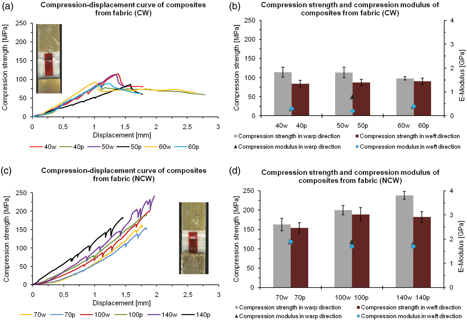
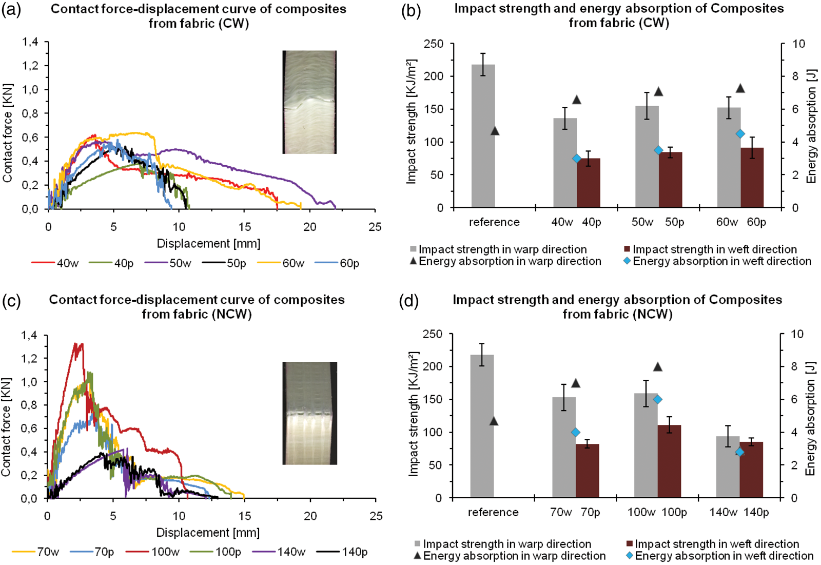
Impact Strength
The results of the impact tests are presented in Figure 10. With increased weft density, the CW composites exhibited increased impact strength and energy absorption in the warp (approx. 155 KJ/m2, 7.2 J) and in the weft directions (approx. 91 KJ/m2, 4.3 J). Due to the yarn crimp in the fabric structure, the CW specimens had a higher displacement in the warp direction (up to 22 mm). As mentioned earlier in the paper, the yarn crimp in the CW specimens can be made responsible for the higher displacement values in the composites. This improved the energy absorption and the impact strength by spreading the stresses more efficiently over a higher strain to failure despite the increase of the weft density. On the other hand, maximum value of contact force (0.65 kN) is reduced due to the yarn damage and yarn crimp in the composite structure (Figure 10(a)). The impact strength of NCW composites (with 100 weft yarns per 10 cm) measured a maximum of 158 KJ/m2 and 108 KJ/m2 in both directions. Once the maximum value was reached, the values in both directions decreased owing to the limited spreading the stresses by increasing of the weft density. The stretched yarn arrangement in the fabric structure leads to a less displacement (15 mm) and yarn damage, which contribute to a higher contact force (up to 1.35 kN) and lower energy absorption in both directions. The recorded values show that the impact behavior of the thermoplastic composites constructed of woven preforms is dependent on the orientation of the GF/PP hybrid yarns in the fabric and the extent of yarn damage obtained during the weaving process as well as the fiber volume content of the reinforcing fibers.
Less fiber damage from gentler processing with a combination of weaving technique and stretched yarn arrangement (non-crimp) result in NCW 2D composites which produce significantly better values in both the warp and weft directions for tensile strength, compressive strength and flexural strength compared to the CW specimens (Figures 6–9). However, the 2D composites constructed of CW manifest better impact behavior, especially impact strength and energy absorption (Figure 10(b) as compared to (d)). Moreover, by modifying the fabric structure, i.e. a z-reinforcement with GF/PP hybrid yarns in multi-layer fabrics (in NCW), the impact strength and energy absorption can be greatly improved. A further optimization of the mechanical properties of spacer fabrics can be achieved by implementing 2D composites made from 3-layer fabrics (NCW) at the outer layers and the crosslinks. Because the 2D fabrics make up the 3D preforms, higher mechanical values for the tensile, compressive and flexural strength of woven 3D spacer fabric composites (3D FRP) made from GF/PP hybrid yarns by the integral structure are expected.
Electrical Properties of Conductor Threads in the 2D Woven Composites
As can be seen from Table 3, the woven connections with layouts (c) and (d) have the lowest connection resistance for both the tinned copper wire and the carbon filament yarn. However, the connection layout (c) exhibits the best reproducibility for the electrical connection as can be seen in the small standard deviations of the measured connection resistance. Connection layout (a) is inappropriate for the textile manufacturing of electrical connections, as the reproducibility of the electrical connections is not satisfactory. The connection layouts that use two or more threads in parallel exhibit a lower connection resistance per thread crossing than the connection layouts with single threads. The lowest connection resistance and most reliable connection were realized in the layout with two parallel threads in a plain weave (c). When looking at the different materials used for conducting threads, the measured connection resistance for the carbon filament yarn is 50 to 100 times higher than that of the tinned copper wire. This may be due to the sizing agent encompassing the carbon filament yarn.
Conclusion & Outlook
2D composites were produced from CW fabrics (with yarn crimp) and 3-layer NCW fabrics (without yarn crimp) with different weft densities to increase the required fabric stiffness. The gentler processing of the fibers during the weaving process despite increasing of the weft density and their stretched arrangement (non-crimp) contributed to significantly better mechanical properties of tensile strength, compressive strength and flexural strength in both the warp and weft directions. On the other hand, the 2D composites made from the CW fabrics, delivered better and reproducible values for impact behavior in both directions despite increasing of the weft density. 2D composites made from CW preforms are predestined for applications where good impact behavior is critical. In turn, 2D composites made from 3-layer NCW present themselves as an excellent solution for those applications requiring greater tensile, compressive and flexural strength for the manufacture of FRPs as in lightweight engineering concepts.
In this study, the electrical connection resistance of the woven interconnections was examined. Four different connection layouts were developed and applied to test specimens made of GF/PP hybrid yarns with tinned copper wire and carbon filament yarn used as conducting threads. The measured connection resistance ranged in the milliohms for the tinned copper wire and ranged in a few ohms for the carbon filament yarn, respectively. These results show the applicability of woven electrical connections. Utilizing this technology to woven 3D spacer fabric structures enables the integration of sensor networks into 3D composite components.
Footnotes
Acknowledgment
The authors would like to thank the German Research Foundation (DFG) for the financial support of the Collaborative Research Centre “Textile-reinforced composite components for function-integrating multi-material design in complex lightweight applications” (SFB 639, TP A3 & D3) and of CH 174/17-1 at the Technical University of Dresden, Germany.