
Abstract
In the present study, filament wound pipes were fabricated by glass and polypropylene (PP) yarns with the three different filament winding angles 55°, 70°, and 82°. Glass and PP yarns were wound around the pipe with two methods; layered and hybrid. Epoxy resin was applied as a matrix to manufacture composite samples. It should be mentioned that composite samples were made in different layers. The three-point bending test was carried out on all samples to investigate the bending behavior of the composites. The experimental results showed that the winding angle 55° is better than other angles in terms of improving the flexural strength of the composite. Moreover, using hybrid yarn to fabricate the composite sample increases the flexural strength and energy absorption of the composite. In the next step, a multi-scale finite element model was applied to predict the flexural behavior of the composites. In this model, a unit-cell of each composite structure was modeled at the meso scale and elastic constants of the composites were extracted by a Python code. In addition, failure parameters for the composites were determined according to micromechanical equations. All elastic and failure parameters were utilized for the macro model and simulation three-point bending test. The numerical results were compared with the experimental and a good agreement could be observed between numerical and experimental results. So, the proposed model is proper to predict the mechanical behavior of the filament wound composite with high accuracy.
Keywords
Introduction
The advantages of polymeric composite pipes for chemical, petroleum, and processing industries are the reduction of capital costs and operating expenses. These pipes propose considerable cost advantages over metals, due to a considerably higher specific strength. Besides, having superior strength, stiffness, and service life makes polymeric pipes imperative to determine leakage integrity and reliability of a piping system [1–3]. Moreover, rotating shafts, robot arms, and other sports and leisure goods are currently fabricated by polymeric composite pipes [1]. Consequently, numerous scientific investigations have focused on filament-wound composite pipes (FWCP) [4–6]. In this way, both experimental setups and numerical methods have been used to evaluate the mechanical properties of FWCPs [7,8]. The first theories of FWCP under bending may be funded by Jolicoeur and Cardou, whereas an analytical solution was developed to obtain stresses and displacements of coaxial hollow cylinders made of orthotropic materials subjected to bending, tensile, and torsion loads [9]. In most studies FWCPs have been considered as thin-walled cylindrical shells, meanwhile, FWCPs are thick-walled composite shell structures. Moreover, there is little work done concerning sandwich FWCPs in particular. However, Xia et al proposed some analytical procedures to investigate the stress–strain responses of FWCPs as thick-walled cylinders under internal pressure loading and lateral compression [10–12]. On the other hand, there are numerous researches on the performance improvement of FWPC in the literature. Akkus and Kawahara improved the bending strength of thin circular carbon reinforced epoxy pipes by reinforcing ring nodes. Four-point bending test results revealed a distinct effect of the reinforcing rings to delay the onset of the sectional localization [13]. Jia et al showed that pre-crack and subsequent failure in the carbon filament wound cylinder were strongly dependent on the pre-crack angle due to deflection and penetration competition of crack evolution [14]. Recently, a four-axis filament winding machine has been used to produce complex filament wound structures by two axisymmetric geometries including a convex and a concave one. Moreover, a numerical method was developed to predict the evolution of the winding angle over the structure surface [15].
The effect of winding pattern on the stress state of filament wound composite flywheel disks has been investigated by using the finite element method (FEM) [16]. Stress and deformation of multiple winding angle hybrid filament-wound thick cylinder under axial loading and internal and external pressure was investigated by Xing et al (2015). The research indicated that material utilization and working pressure can be increased by using multi-angle filament winding procedure [17]. Maa et al investigated the energy absorption properties of carbon/aramid fiber filament winding composite tubes. Energy absorption ability was studied by quasi-static compression tests and microscope observation of failed cross-sections. The hybrid product at optimized fabrication conditions proposed high energy absorption components whose specific energy absorption was near 100 kJ/kg which could be used on vehicles [18].
The benefits of the addition of nano-particles, e.g. carbon nanotubes (CNTs) and/or boron nitride nano-plates (BNNPs), during the filament winding process, have been recently reported by Zhang et al and Ustun et al. The authors conclude that strengthening the fiber-matrix interface leads to improve the mechanical performance of the composite pipes [19,20]. Prediction of the mechanical behavior of composites materials has been one of the concerns of researchers. Multi-scale finite element modeling is one of the considerable methods to predict the mechanical properties of the composites. In this method, a representative volume element (RVE) of the composite is created and periodic boundary conditions are applied to the RVE. Afterward, mechanical constants are calculated from the meso scale model and used for the macro model under different loads [21–24]. Using fiber properties at the meso scale in this method leads to improve the accuracy of the model. Moreover, some studies have been conducted to predict the mechanical behavior of the filament wound composite pipe under different loads by applying finite element model [25–27]. They used a macro model to simulate the mechanical behavior of the composite and the multi-scale finite element model was not used for this purpose.
As has been shown, the assessment of the mechanical properties of filament wound composite structures has been considerably investigated by researchers. Moreover, hybrid multiple layered filaments wound pipes are today known as a new version of composite pipes. Therefore, in this study filament wounded composites were fabricated by polypropylene and glass yarns, utilizing two different multiple layers and hybrid layers. The flexural behavior of the composites was analyzed by a three-point bending test and the results were compared with a composite that was fabricated by glass/epoxy materials. Besides, a multi-scale finite element model was applied to predict the bending and failure behavior of the composite. Finally, numerical results were compared with experimental results and discussed.
Materials and methods
The test specimens were made of glass/polypropylene filaments, while the control sample was fabricated by glass/epoxy. Table 1 demonstrates the general properties of textile filaments and chemical resin used in this study.
General properties of epoxy, glass, and polypropylene filaments used in this study.

aThe mass (gram) of 1000 meters of any fiber and/or yarn known as Tex.
Zwick Tensile testing machine 1446, Germany was used to obtain tensile properties of filament yarns. In addition, the density was measured by Kern & Sohn GmbH PL 360/3, Germany apparatus.
Manufacturing process
An experimental winding machine was used to produce different samples of composite pipes. The real configuration of the machine and a filament wound pipe is shown in Figure 1.

(a) The real configuration filament winding machine used in this study, (b) a filament wound pipe sample.
The manufacturing variables included production system (layering vs. mingling), winding angle (55°, 70°, and 82°), number of layers (5, 7, and 9), and materials (glass/epoxy vs. glass/polypropylene/epoxy). The winding speed and yarn tension were 35 mm/s and 5 N respectively. Figure 2 shows the different filament wound layers to produce a range of composite pipes.

Different filament wound layers to produce a range of composite pipes.
In order to change the winding angle, the velocity of the traverser was changed and the winding angle could reduce or increase. Moreover, Table 2 indicates the experimental design of the work including all filament wound pipe samples fabricated in this study.
The experimental design of the work.

According to trial and error results, it was found that poly tetra fluoroethylene (PTFE: known as Teflon in the market) is the best material to use as a mandrel compared to metal and cellulose mandrels as shown in Figure 3.

Poly tetra fluoro ethylene (PTFE: known as Teflon in the market) mandrel used in this study.
To produce glass/polypropylene/epoxy filament wound composite pipes, the conventional filament winding method was used in which glass filaments and/or glass/polypropylene hybrid filaments were being passed through an epoxy resin pad-batch system. Consequently, the produced composite pipe samples were put into an oven at 80°C for 20 min. at the constant pressure of 0.3 MPa [28,29].
Experimental tests
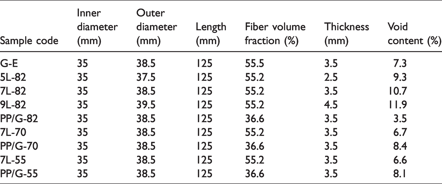
The composite pipe dimensions were measured according to ASTM D3576. Consequently, ASTM D3171-11 was used to obtain the constituent content of composite samples, i.e. fiber and matrix volume fractions. Table 3 shows the dimensions, fiber volume fraction, and void content of filament wound composite pipes produced in this study.
Dimensions, fiber volume fraction, and void content of filament wound composite pipes produced in this study.
Depending on the final application, FWCPs especially in constructions of complex pipelines can be subjected to bending [2]. Consequently, exceeding of allowed stresses may cause failures which can be seen in cracked fibers, matrix cracking, and/or delimitation. Therefore, it is important to investigate reliable criteria of behavior for FWCPs exposed to bending [2,3]. For these reasons, the flexural properties of fabricated composite pipes were investigated. Consequently, a three-point bending test was performed by using Hounsfield, H25HS, UK apparatus according to ASTM D790-03. Because of the ductile behavior of the composite and some papers which were used a three-point bending test to investigate the bending behavior of the filament wound composite pipe, in this study three-point bending test was utilized [30–33]. For this purpose, the apparatus was set on the span length of 110 ± 10 mm having roller supports of φ = 6.47 mm. The test speed was 1.5 ± 0.5 mm/min. Figure 4 shows the conditions of the bending test used in this study.

The conditions of the bending test used in this study.
The outputs of the bending test were included the ultimate flexural stress, the maximum flexural deflection. The ultimate flexural stress (σu) of composite pipe samples could be calculated through [34]: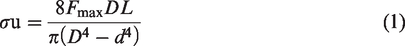
Finite element multiscale modeling
Meso scale
In order to simulate the flexural behavior of the filament wound pipe, mechanical constants of each layer should be obtained. For this purpose, a unit cell of each layer was created in the ABAQUS finite element software. The unit cell includes the yarn that is surrounded by the epoxy matrix.
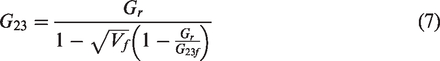
During the composite production process, the yarn was impregnated with resin. Impregnated yarn is assumed as a unidirectional composite with fiber volume fraction equal to the packing density of the yarn:

The Chamisa [35] micromechanical model is used to calculate the elastic constants of transversely isotropic unidirectional composites.


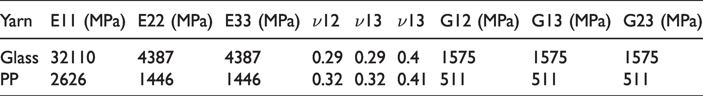
The elastic constants of the yarn impregnated with resin are given in Table 4.
Elastic constants of the yarn impregnated with resin.
Periodic boundary conditions were applied to the unit cell. Figure 5 shows periodic boundary conditions that were applied to the unit cell.

Periodic boundary conditions, (a) tensile load, (b) shear load.
C3D8R element type in ABAQUS/Standard element library, which is an 8-node linear, was applied for meshing the PP/epoxy and glass/epoxy model. For mesh generating the matrix of the hybrid sample, C3D10 element quadratic tetrahedron was used. Figure 6 shows the unit-cell after the meshing process. A Mesh dependency study was performed on the model to make sure that the results are independent of the mesh size.

Mesh generation on the unit cell, (a) PP/epoxy, (b) PP/glass/epoxy (hybrid).
The representative unit cell of composite samples is assumed to be homogeneous and orthotropic. Thus, the stiffness matrix for an orthotropic material is given in equation (11) [36]: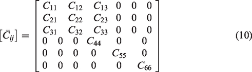
For the homogeneous composite material, the relationship between average stress and strain is:


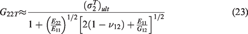
Where V is the volume of unit-cell. Therefore, a python code was employed in order to calculate average volume stress as well as obtain stiffness matrix components. To predict the flexural strength and damage evaluation of each sample, Hashin model [38] was employed. In the Hashin model, the tensile and compressive strength of each layer in the fiber and transverse directions should be obtained. Hence, Chamis [39] equations were employed to calculate strength parameters for each layer:


Macro model
ABAQUS/Explicit package was applied to finite element (FE) simulation of the flexural behavior of the filament wounded pipes. In the first step, a pipe with a 35 mm diameter was created as a shell and deformable body. Other parts such as bases and load bar were modeled as rigid bodies. The mechanical properties of each layer according to outcomes of the meso scale model were applied to the macro model. Plies angles and the number of plies were assigned to the model according to the experimental program. The whole model containing filament wound pipe and rigid bodies were assembled in the right places regarding the flexural test.
Boundary conditions are applied to the reference points of loading instruments, which are defined as rigid parts. All degrees of freedom for bases were closed as the experimental test. The displacement load in the FE simulations was applied through the load bar with the diameters the same as the test apparatus. To mesh generation, S4R element type in ABAQUS/Explicit with reduced integration and hourglass control, which is a 4-node linear brick, was applied for the filament wound pipe. Figure 7 shows mesh generation in the macro model. It should be mentioned that in this study composite samples with winding angles 70° and 82° were simulated.

Mesh generation of a model.
Results and discussions
As can be seen from Table 3, the void content of samples produced by the mingling of glass and polypropylene filaments is significantly less (about one-third) than those fabricated by the layering method. This phenomenon may be because slippage of glass filaments on polypropylene filaments would make some gaps between neighboring layers which could increase the void content of layered filament wound samples. Figure 8 shows the flexural strength of all samples.

Flexural strength of filament wound pipe samples.
According to Figure 8, in samples with winding angle 82 and PP/glass layers (5 L-82, 7 L-82, and 9 L-82) by the increasing number of layers from 5 to 7, flexural strength improved but in 9 layers flexural strength decreased. It should be considered that an increasing number of layers leads to the compact force between layers is increased. The transverse strength of glass fibers is low and increasing compact force cause to damage glass fibers. This occurrence reduces the flexural strength of the composite. Thus, a reduction in flexural strength can be seen when the number of layers is increased from 7 to 9.
The flexural strength of 7 L-55 is more than 7 L-70 and 7 L-82 because of the winding angles of the fibers. It can be concluded that with the winding angle of 55°, fibers lie through the load distributions and can resistant to external load in comparison with the winding angle 70°. It has been proved that the induced stresses and strains depend strongly on winding angle when a composite structure has filament-wound anisotropic layers [40]. Moreover, theoretical predictions confirmed that lower winding angles increase flexural stress and reverse. In other words, smaller winding angles result in an increase in flexural strength which comes across with the results obtained in this study [13]. Fortunately, Akkus et al. [32] have also concluded that the ultimate strength of filament wound composites can be decreased by the winding angle that is the same obtained by both numerical and experimental results in this work. It is worthy to note that by the decrease of winding angle, filaments align with the main horizontal axis of the cylinder composite which results in more axial tensile strength and a more reinforcing effect. That is why the 7 L-55 composite sample proposes the most flexural strength compared to 7 L-70 and 7 L-82 samples. This phenomenon can be observed in samples PP/G-55, PP/G-70, and PP/G-82.
As mentioned before, the number of layers in 7 L-82 and G-E is the same (7 layers). But, the flexural strength of 7 L-82 is more than G-E. The reason for this result is related to the materials of each sample. Glass/epoxy is the main material for fabricating the G-E sample but in 7 L-82, 7 layers of glass/epoxy and PP/epoxy were used. Glass fibers have low transverse strength. During the bending test, the upper surface is under pressure stress and because all layers of the G-E sample include glass fibers, it can be seen the failure occurs in this sample faster than 7 L-82 that containing glass and PP fibers in its layers. In order to analysis the failure mechanism of the composite, the fracture surface was observed using a scanning electron microscope (Figure 9).

Scanning electron micrographs of fracture surfaces of the composite, (a) fiber crushing, (b) fiber delamination.
Once a bending load is applied by the upper roller, creacks propagate within the composite because of pressure load on upper surface. Due to this pressure load, some of fibers are crushed and they cannot contribute on reinforcing of the composite (Figure 9(a)). Moreover, near the are that a crack is created, delamination between fibers and matrix can be observed which is reduced the bending strength of the composite (Figure 9(b)).
To fabricate PP/G samples, PP and glass yarns were twisted and used for each layer. Indeed, in each layer PP and Glass fibers present and reinforce the composite layer simultaneously. According to Figure 8, the flexural strength of PP/G-55 and PP/G-70 is more than the G-E sample. The presence of PP and glass fibers in each layer leads to improve longitude and transverse strength of the composite layers. Glass fibers improve longitude strength and PP fibers fix the low transverse strength of glass fibers. Because of these advantages, the flexural strength of hybrid samples is improved. An ANOVA test was used to study the significant effect of winding angle on the bending strength of the composite. Table 5 shows the results of the ANOVA test for this study.
The ANOVA analysis for this study.

The outcomes revealed that the winding angle has a significant effect on the bending strength. The load-deflection curve of each sample according to the composite structure is shown in Figures 10 and 11.

Load–deflection curves of composite samples with 7 and 9 layers.

Load–deflection curves of composite samples with 5 layers.
With respect to Figures 10 and 11. G-E sample shows a brittle behavior in the fracture point. The reason for this behavior is using glass fibers to fabricate all layers of the composite. On the other hand, other samples that were used also PP fibers for producing filament wound pipe have ductile behavior after the ultimate point. It shows that using PP and glass fibers especially in the form of hybrid improves the mechanical properties of the composite after failure point. According to Figure 10, after critical bending load, an extreme drop in the load can be observed. Manufacturing the composite with glass and epoxy gives a brittle failure to the composite and reduces the energy absorption after the failure point. However, using PP yarn within the composite structure not only improves the flexural strength of the composite but also increases energy absorption of the composite after failure. The reason for this phenomenon is the ductile behavior of the PP yarn that affects on flexural behavior of the composite.
In the next step, a multi-scale finite element model was applied to predict the flexural behavior of the filament wound pipe composites. In this method, the mechanical properties of the composite were extracted from a meso model and used for the macro model under flexural load. Figure 12 shows the stress contours of the unit cells.
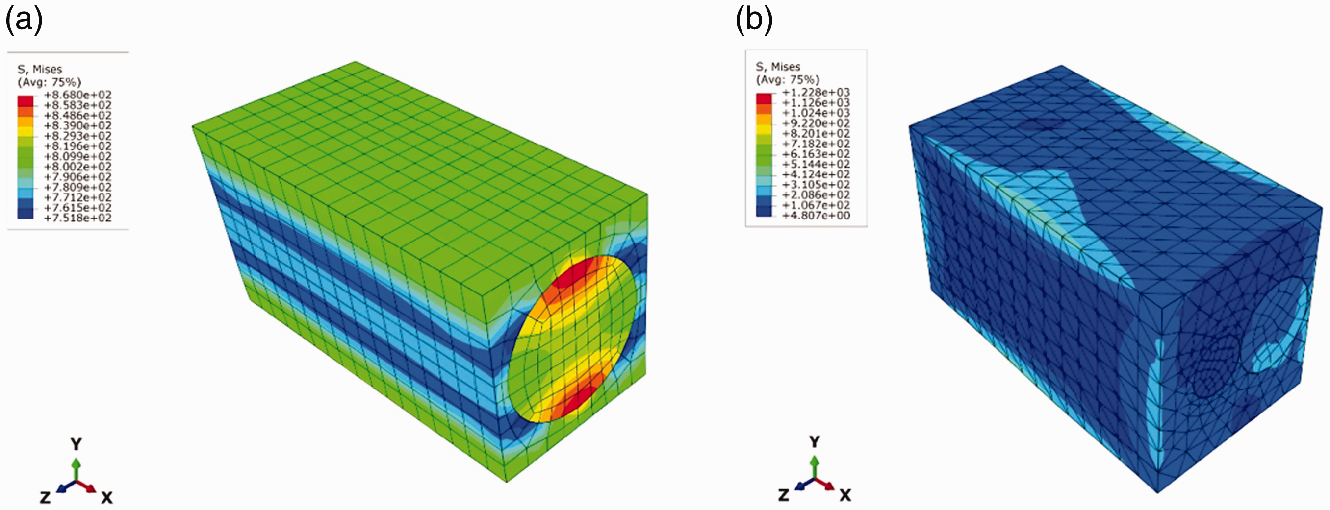
Stress contours in meso model, (a) PP/epoxy, (b) PP/glass/epoxy (hybrid).
All outcomes from the meso model which were used as input data in the macro model are shown in Table 6.
Mechanical properties outcomes from the meso model for each composite layer.

Figure 13 shows deformations in the macro model and an experimental sample.

Deformation of E-G sample; (a) FE simulation, (b) experiment.
Figure 13 indicates an extreme fracture on the top surface of the sample that this phenomenon can be seen in the experimental sample and numerical model. To a comparison between FE and experimental results, load-deflection curves for the FE model and experiment are shown in Figures 14 and 15.
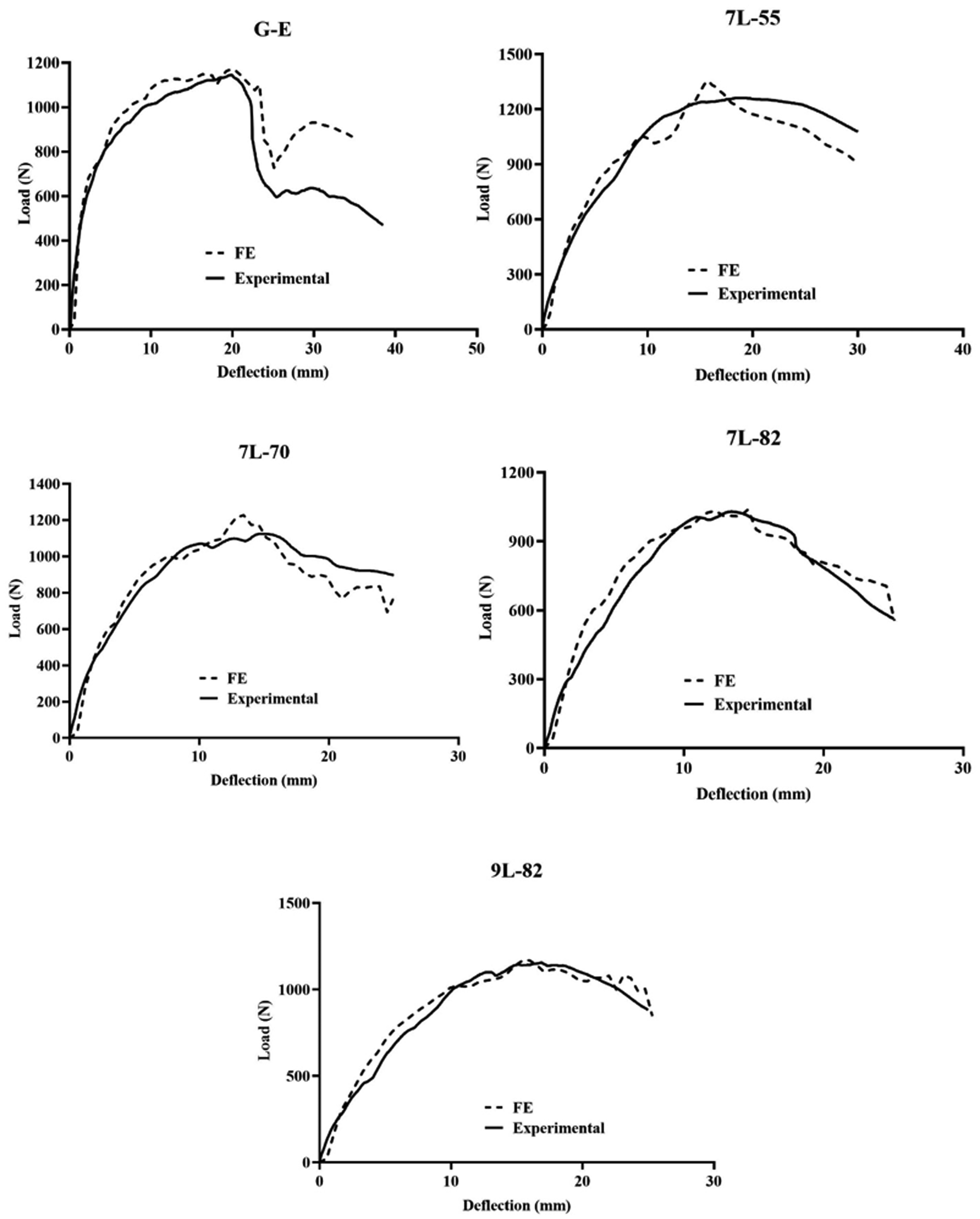
Load–deflection curves for experimental and FE results (samples with 7 and 9 layers).
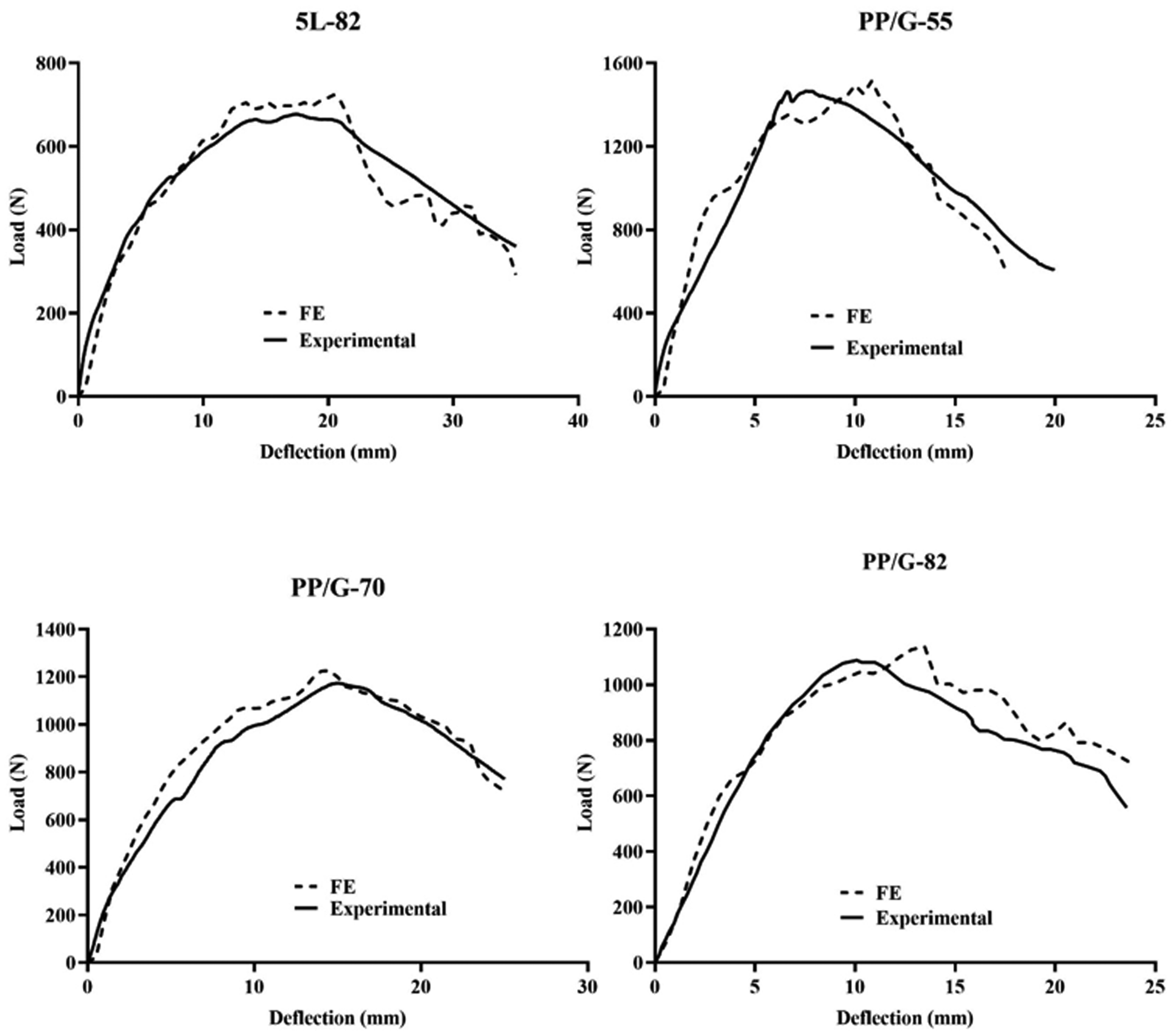
Load–deflection curves for experimental and FE results (samples with 5 layers).
According to Figures 14 and 15, the numerical results have good agreement with experimental results in elastic and damaged parts. But multiple differences can be seen between numerical and experimental curves. It should be mentioned that during the filament winding process, the lower layers compact by the upper layers that this issue can damage the glass fibers and change the final mechanical properties of the composite. Moreover, the cross section of the yarn during the filament winding process change to an uncircular shape but in the FE model circular shape for the cross section of the yarns was assumed. So, changing the cross section can affect on mechanical properties of the composite layer. Besides, in this study, the tensile and compressive fracture toughness were assumed the same. This assumption can change the model’s results. Table 7 shows a comparison between numerical and experimental results in the prediction of flexural strength.
Comparison between experimental and numerical results in flexural strength.

It can be observed that the numerical model could predict the flexural strength of the composites with low errors. Some reasons such as damage of fibers during filament winding or changing the cross section of the yarns lead to increase error in the numerical results. According to experimental and numerical results, it can be concluded that producing hybrid filament wound pipes by mingling glass and PP yarns have more advantages compared to fabricate hybrid filament wounded pipe with glass/epoxy and PP/epoxy layers. Mingling layers have more compressive strength in comparison with glass/epoxy layers and it can improve the flexural behavior of the composite with fewer layers than composite pipes with glass/epoxy and PP/epoxy layers. Moreover, using multi-scale finite element modeling leads to predict mechanical properties of the composite and improve them by changing parameters and make an optimum product.
Conclusion
In this study hybrid filament wound pipes were produced by two methods. In the first methods, glass and PP yarns were wound separately while making different layers of glass/epoxy and PP/epoxy. In the second method, glass and PP yarns were hybrid and wound around the pipe. Epoxy resin was used as a matrix material to produce composites. In this study, the winding angle and properties of layers (hybrid or layered) were variable parameters. A three-point bending test was carried out on all samples. According to the experimental results using hybrid layers (hybrid or layered) improve flexural strength in comparison with using just a glass/epoxy for all layers. The presence of PP fibers in some layers or beside the glass fibers in the same layers leads to improve transverse properties of the composite pipes and increases the compressive strength of the composite layer. Moreover, in the same number of layers, orientation angle 55° showed better flexural strength than 70° and 82° because of the arrangement of fibers through the direction of load. Besides, composites with layers containing mingling glass and PP yarns had higher flexural strength against composites using PP/epoxy and glass/epoxy layers separately. The presence of PP and glass fibers improve the longitude and transverse properties of the layer simultaneously.
In the next step, a multi-scale finite element model was utilized to predict the flexural behavior of the composite samples. In this model, a unit cell of the composite was created in ABAQUS software and mechanical properties of the composite such as elastic constants, strengths through fibers and transverse directions, and fracture toughness were extracted. The output data from the meso model were used as input data for the macro model. The numerical results had good agreement with experimental results to predict the elastic and failure behavior of the samples. Therefore, by changing variable parameters in the model an optimum composite can be achieved and reduce product costs.
Footnotes
Declaration of conflicting interests
The author(s) declared no potential conflicts of interest with respect to the research, authorship, and/or publication of this article.
Funding
The author(s) received no financial support for the research, authorship, and/or publication of this article.