
Abstract
The glass epoxy polymer composites are extensively used for a wide variety of applications in aerospace, automotive, and chemical industries due to an excellent property profile. Even though these composites are produced as near net shapes, the machining has to be performed in the final stage of production. Drilling is one of the most common machining processes used to install the fasteners for assembly of laminates. However, the drilling of these composites is rather a difficult task due to the highly abrasive nature of reinforcement and hence there is a need to study the machining performance. An attempt has been made in this article to investigate the effects of spindle speed and feed on machinability aspects, namely, thrust force, hole surface roughness, and specific cutting coefficient during drilling of glass epoxy composites. The drilling experiments were performed as per full factorial design for both glass epoxy composites and silicon carbide-filled glass epoxy composite materials. The response surface methodology based mathematical models were developed for analyzing the effects of cutting conditions on machinability characteristics. The parametric analysis reveals that the silicon carbide-filled glass epoxy composite material provides better machinability compared to glass epoxy composite without the addition of filler.
Keywords
INTRODUCTION
The composite materials find wide applications in a variety of parts due to the combinations of several properties, which cannot be attained with metals, ceramics, or polymers. Nowadays, the polymer matrix composites have replaced many conventional metallic materials [1] and are used for producing a large number of mechanical components such as gears, pump impellers, cams, wheels, brakes, clutches, bearings, and seals [2]. The glass fiber, carbon black, and CaCO3 are added to the polymer composites in order to improve stiffness, strength, hardness, and modulus [3,4].
The glass epoxy composites are polymer composites, which show numerous advantages in several fields of engineering such as aircrafts, automobiles, chemical industries, defense, ships, medical applications, bio mechanics, sports equipments, robots, and machines due to an excellent property profile such as high-specific stiffness and strength, high damping, good corrosive resistance, and low thermal expansion [5]. The fillers affect the tensile properties according to their packing characteristics, size, and interfacial bonding [6] and improve the fracture toughness of epoxy resin [7]. The fillers not only reduce the cost of composites but also meet the performance requirements, which could not have been achieved using reinforcement and resin ingredients alone [2]. Further, the different fillers are added to reduce the friction and improve the wear properties [8–16]. As a result of improved properties and potential applications, there exists a great necessity to understand the problems associated with the machining of these composites.
The machining of glass epoxy polymer composites differs drastically in several aspects from the machining of conventional metals and alloys. Further, the machining of these composites is rather a complex task owing to its heterogeneity and anisotropic nature of the composite. Moreover, the reinforcements are extremely abrasive and responsible for complex deformation behavior, high tool wear, and poor surface finish. Even though the glass epoxy composites are produced to near net shapes, an additional operation such as drilling is essential to install the fasteners for the assembly of the composite laminates. In aircraft industries, the drilling of these composites is carried out for the purpose of joining using rivets, bolts, and nuts.
The successful performance of machining operation is affected by work material properties. The properties as well as the characteristics of work materials are expressed in terms of machinability. The cutting force, power, specific cutting pressure, tool wear, tool life, and surface roughness are some of the criteria, which are used to assess the machinability characteristics. Although the machinability refers to work materials, the performance of machining depends upon several parameters such as cutting conditions, tool material, tool geometry, and machining operations [17]. Several researchers carried out experimental investigations on the machining characteristics of polymer composites. The literature survey regarding the machinability aspects of polymer composites machining by some of the authors is discussed below.
Rahman et al. [18] reported that the polymer softening action is responsible for achieving a better surface finish rather than tool geometry of cutter for machining of carbon/polyetheretherketone (PEEK) composites. Chambers and Bishop [19] compared the machinability study of carbon/epoxy and carbon/PEEK composites using different cutting tools. The effect of cutting parameters on the various aspects of machinability during turning of PEEK, PEEK CF30, and PEEK GF30 work materials using cemented carbide and polycrystalline diamond tools was studied by several researchers [20–24]. Gaitonde et al. [25,26] have presented an investigative study on the machining of PA6 and PA66 GF30 polyamides using response surface methodology (RSM) based mathematical models for studying the effects of cutting speed and feed on machinability. Gaitonde et al. have also employed Taguchi technique [27] and artificial neural network [28] for studying the machinability characteristics of unreinforced and reinforced polyamides.
The machinability of metal matrix composites (MMC) reinforced with silicon carbide (20%) using polycrystalline diamond (PCD) inserts was studied by considering the cutting time of tool wear, cutting forces, and surface roughness of workpieces [29–31]. Antonio and Davim [32] applied the genetic algorithms (GA) for optimizing the cutting speed, feed rate, and cutting time in the turning of MMC with PCD tool. Davim [33] also used the Taguchi method to investigate the cutting performance during the turning of MMC using PCD inserts. Sahin [34] carried out an investigative research on tool wear during turning of SiCp-reinforced aluminum matrix composites. Manna and Bhattacharyya [35] examined the influence of cutting parameters on surface roughness of workpieces during turning of Al/SiC–MMC. Ciftci et al. [36] analyzed the effects of cutting speed and coating of tool on tool wear during SiCp-reinforced Al-2014 alloy matrix composites machining. Kilickap et al. [37] studied the behavior of tool wear and work surface roughness during machining of silicon carbide-filled MMC using cemented carbide tools. The exhaustive literature review by Basavarajappa et al. [38] on the machining of MMC reported that the selection of machining parameters for optimal surface finish, tool life, and cutting forces depends on matrix material, reinforcement type, volume fraction, and size of the reinforcement.
Davim and Antonio [39] presented the experimental and numerical studies on cutting forces, tool wear, and surface finish during drilling of particulate MMC and the optimal drilling process parameters were determined. Davim and Antonio [40] also proposed the GA approach for optimizing the cutting conditions in the turning and drilling of aluminum matrix composites considering machining forces, surface finish, and tool wear as the responses. Davim [41] established the relationships between the machining parameters (cutting speed, feed rate, and cutting time) and the various aspects of machinability (tool wear, specific cutting force, and hole surface roughness) in the drilling of MMC. Ramulu et al. [42] reported that the drilling force decreases with the increase in hardness of drill material during drilling of aluminum alloy reinforced with 10 vol.% and 20 vol.% of Al2O3. Basavarajappa et al. [43] investigated the influence of cutting conditions on surface roughness of hole during drilling of Al2219/15%SiCp and Al2219/15%SiCp-3%Graphite (hybrid) composites using multifaceted and coated carbide drills. It was reported that the surface finish could be improved using conventional coated carbide drills when compared to multifaceted carbide drills. The investigative study on the drilling of these materials revealed that the addition of graphite as reinforcement in Al/SiCp composite reduces the thrust force [44] and tool wear [45]. Basavarajappa et al. [46] also observed that the ceramic–graphite reinforced composite has better machinability than the ones reinforced with SiCp composites during drilling of hybrid MMC.
The quality of the drilled holes can be critical to the life of riveted joints for which the holes are used. The various aspects of hole such as wall surface roughness, axial straightness, and roundness of hole cross-section can cause high stresses on the rivet leading to the failure [47]. On the other hand, the delamination is a major problem associated with the drilling of fiber-reinforced composite materials resulting in poor assembly tolerance and long-term performance deterioration. It has been observed that the level of delamination is related to thrust force and the key to solve delamination problem lies in reducing the thrust force of drilling [48]. In order to overcome these difficulties, it is necessary to select appropriate machining parameters due to the fact that an unsuitable choice could lead to unacceptable work material degradation. Hence, this investigation is an effort in this regard where thrust force, surface roughness of hole, and specific cutting coefficient related to thrust have been studied during drilling of glass epoxy composites with and without the addition of fillers. Second-order mathematical models of thrust force, hole surface roughness, and specific cutting coefficient related to thrust have been developed using RSM approach for analyzing the effects of spindle speed and feed. The RSM using statistical design of experiments (DOE) proved to be an efficient modeling tool, which not only reduces the cost and time, but also provides required information about the interaction effects with minimum number of experiments [49]. In this investigation, the experiments were planned as per full factorial design (FFD) of experiments and the adequacy of the quadratic models has been tested through the analysis of variance (ANOVA).
RESPONSE SURFACE METHODOLOGY
The RSM is a modeling tool used for establishing the relationship between the independent parameters and the desired criteria. The RSM is useful for developing, analyzing, improving, and optimizing the process, which provides an overall perspective of the system response within the design space [49]. The modeling of the desired response to various process parameters can be obtained through the DOE and by applying the regression analysis. The DOE provides an occasion to study not only the individual effects of each process parameter but also their interactions with minimum number of experiments for achieving the optimum conditions. Hence, RSM adopts both mathematical and statistical methods for analyzing the interaction effects of the different process parameters on the desired criteria when they are varied simultaneously.
In many situations, it is feasible to represent the independent process parameters in a quantitative form and these parameters can be thought of having a functional relation or response, which can be expressed as [49]:

MATERIALS AND FABRICATION
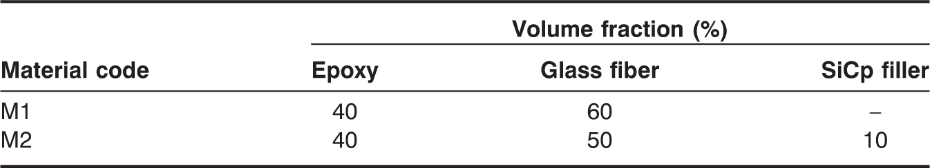
A medium viscosity epoxy resin (LAPOX L-12) with a room temperature curing polyamine hardener (K-6), both supplied by ATUL India Ltd., Gujarat, India, was employed as the matrix material throughout the investigation. Due to good resistance to alkalis and better adhesive properties owing to the cross-linking chain between the resin and the hardener, this matrix material was particularly selected for this study. The seven-mill plain weave bi-directional E-glass fabric (12–16 µm) with epoxy compatible finish was used as a reinforcement material and the silicon carbide (SiCp) as a filler material.
In this investigation, the glass epoxy composite laminates were fabricated using hand lay-up technique with a stacking sequence of [0/90]S. The fabrication procedure consists of placing the glass fibers with epoxy compatible finish on a substrate material, which had a release coat applied on it. A curing agent (hardener) is mixed in the liquid epoxy to polymerize the polymer and to form a solid network cross-linked polymer. The weighed quantities at room temperature curing epoxy resin plus the hardener mix was taken and then smeared over the glass fabric. On this, another layer of glass fabric was laid and the process continued. The entire lay-up was covered with a mat finished fabric over which the steel plate was placed with the required release coat applied on it. The lay-up assembly was pressed in a press. The laminates were cured at ambient conditions for a period of about 24 h. The prepared laminate has a size 320 × 270 × 10 mm3. In order to prepare the silicon carbide (SiCp) filled glass epoxy composites, the silicon carbide fillers of size 400 mesh are mixed with a known amount of epoxy resin. The cured materials are then cut to samples of different sizes for carrying out the drilling experiments.
Composition of samples prepared.
EXPERIMENTAL DETAILS
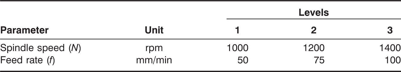
Planning of Experiments
Process parameters and their levels.
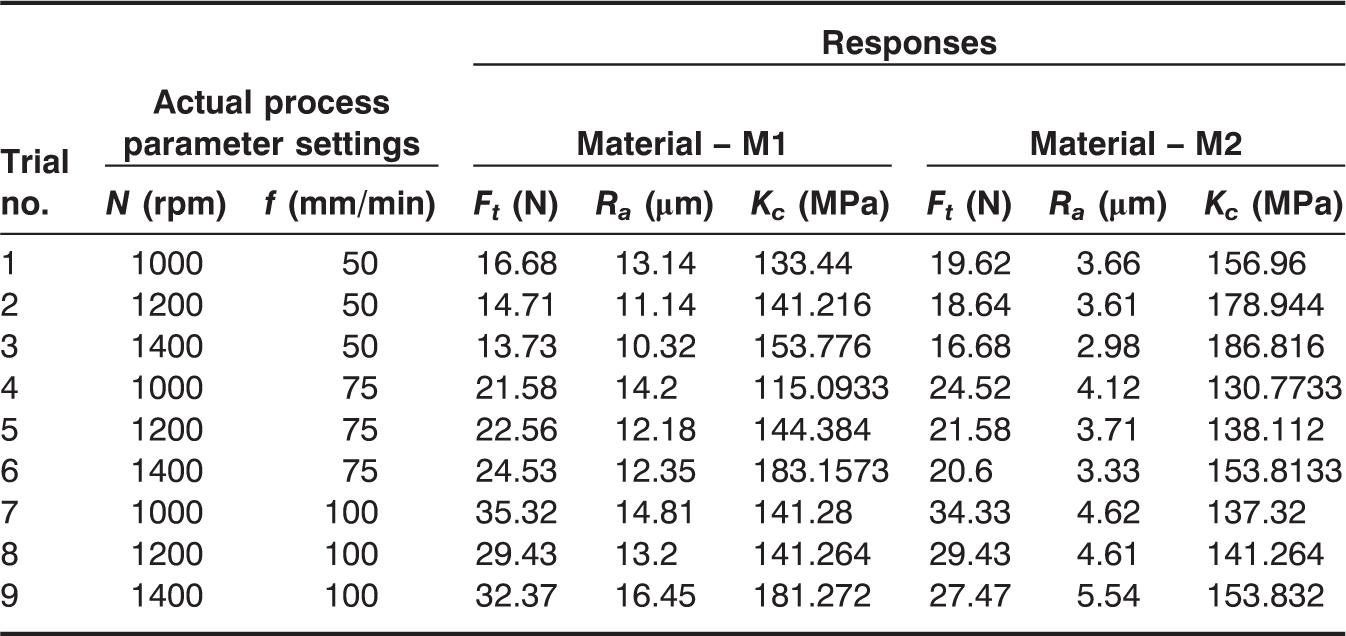
Experimental layout plan and the responses.
Experimentation
The composite materials were cut into strips of size 150 × 90 × 10 mm3. Surya VF30CNCVS vertical machining center was employed to perform the drilling experiments. The machining center is equipped with a maximum feed of 4000 mm/min and a spindle speed of 6000 rpm with 15-kW spindle motor. The proper clamping system was employed for fixing the composite laminates in the machining center; 5 mm diameter solid carbide drill (R850-0500-30-A1A-N20D, SANDVIK) was used throughout the experimentation. A fresh drill was used in every trial for each of the materials tested and hence tool wear is negligible. The trials were randomized in order to remove the effects of any factors unaccounted for.
Evaluation of Machinability Characteristics
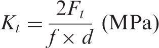
The drilling fixture was mounted on the dynamometer and the thrust force was measured using a strain gage drilling dynamometer. Each trial was repeated twice and the average was taken as the process response. The surface roughness of the drilled hole was measured using Mitutoyo – SJ201 surface finish instrument having a metered cut-off length of 0.8 mm. Each surface roughness value was obtained by averaging four measurements at various positions of the wall surface of hole for each trial. The arithmetic mean of departure of the roughness profile from the mean line was used to evaluate the surface roughness. The specific cutting coefficient related to thrust (Kt) is calculated from the following equation [50]:
Development of Mathematical Models
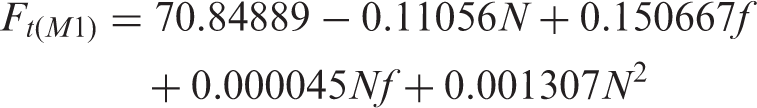
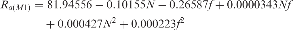
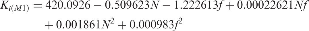
In order to analyze the effects of process parameters on machinability aspects, it is necessary to develop the mathematical models based on RSM. In this study, each parameter was investigated at multi-levels to study the non-linearity effects of the process parameters. Hence, second-order RSM-based mathematical models for thrust force (Ft), surface roughness of the hole (Ra), and specific cutting coefficient related to thrust (Kt) have been developed with spindle speed (N) and feed (f) as the process parameters. The RSM-based mathematical model is of the form [49]:

The values of regression coefficients of the mathematical model are determined by [49]:

THRUST FORCE
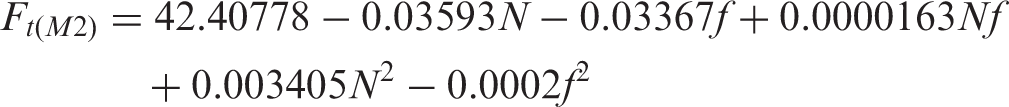
SURFACE ROUGHNESS OF HOLE
SPECIFIC CUTTING COEFFICIENT

RESULTS AND DISCUSSIONS
Adequacy Checking of Machinability Models
ANOVA results for machinability models.
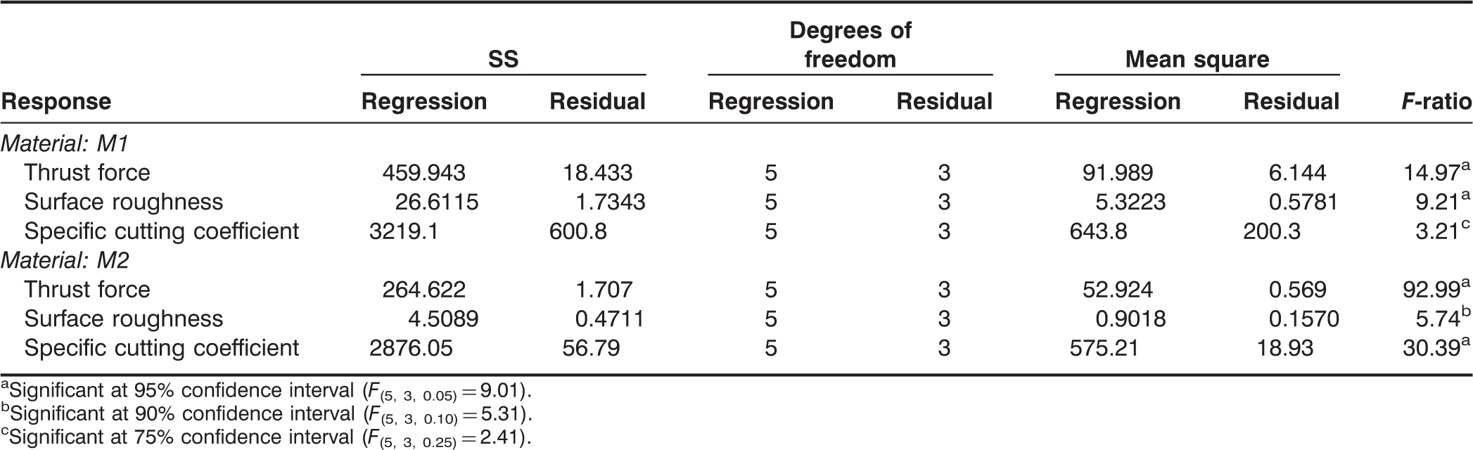
Significant at 95% confidence interval (F(5, 3, 0.05) = 9.01).
Significant at 90% confidence interval (F(5, 3, 0.10) = 5.31).
Significant at 75% confidence interval (F(5, 3, 0.25) = 2.41).
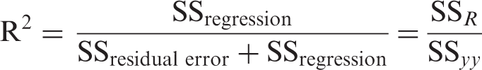
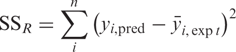
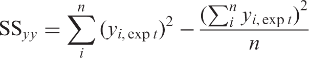
The adequacy of the developed mathematical models is also verified through coefficient of determination (R2) value after estimating the SS. The R2 is used to test the goodness-of-fit of the proposed models, which provides a measure of variability in observed values of response, and can be explained by the controlled process parameters and their interactions [49] and is given by:
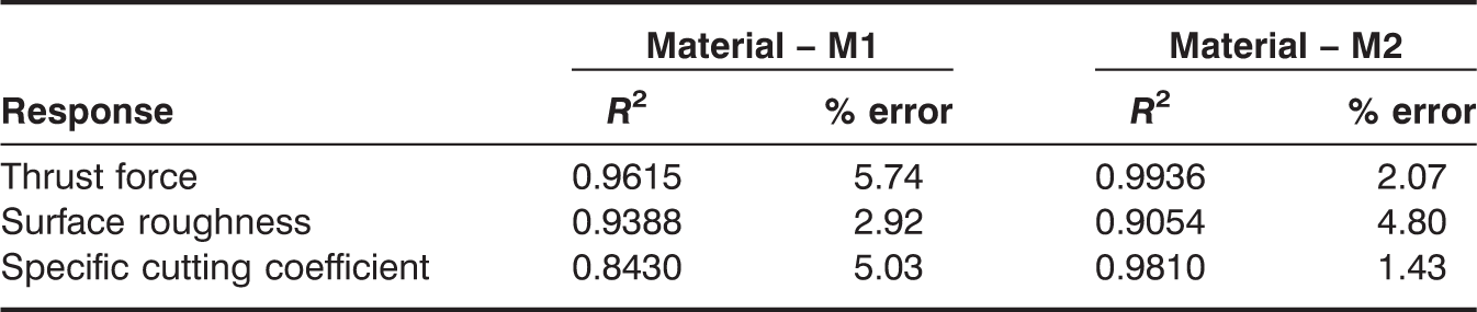
Coefficient of determination values and % prediction error for machinability models.
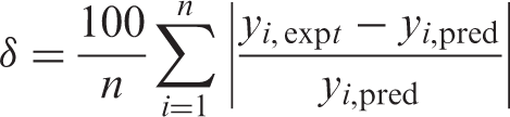
Equations (5)–(10) are used to test the accuracy of the developed quadratic models using the experimental data of FFD. The % prediction error of the model for the experimental data set of FFD is given by:
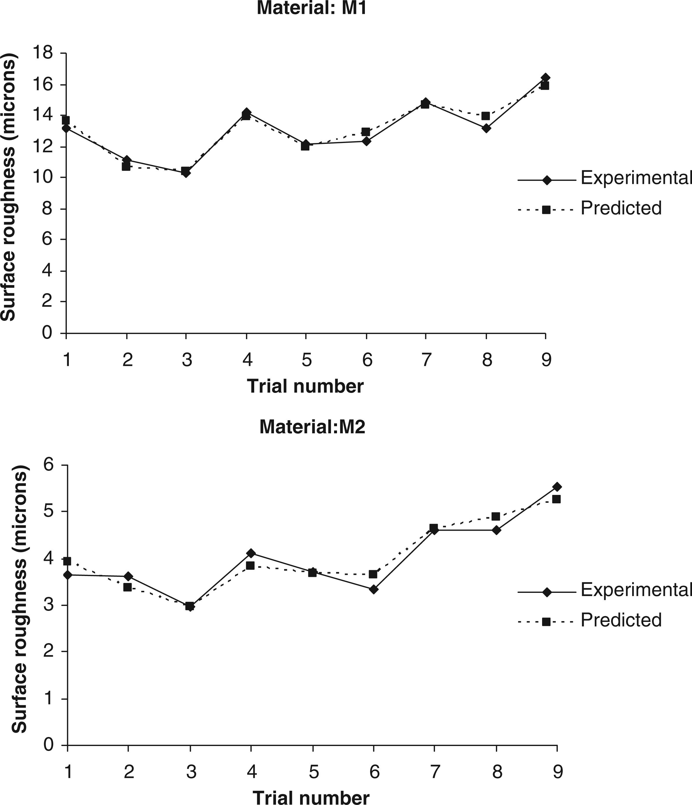
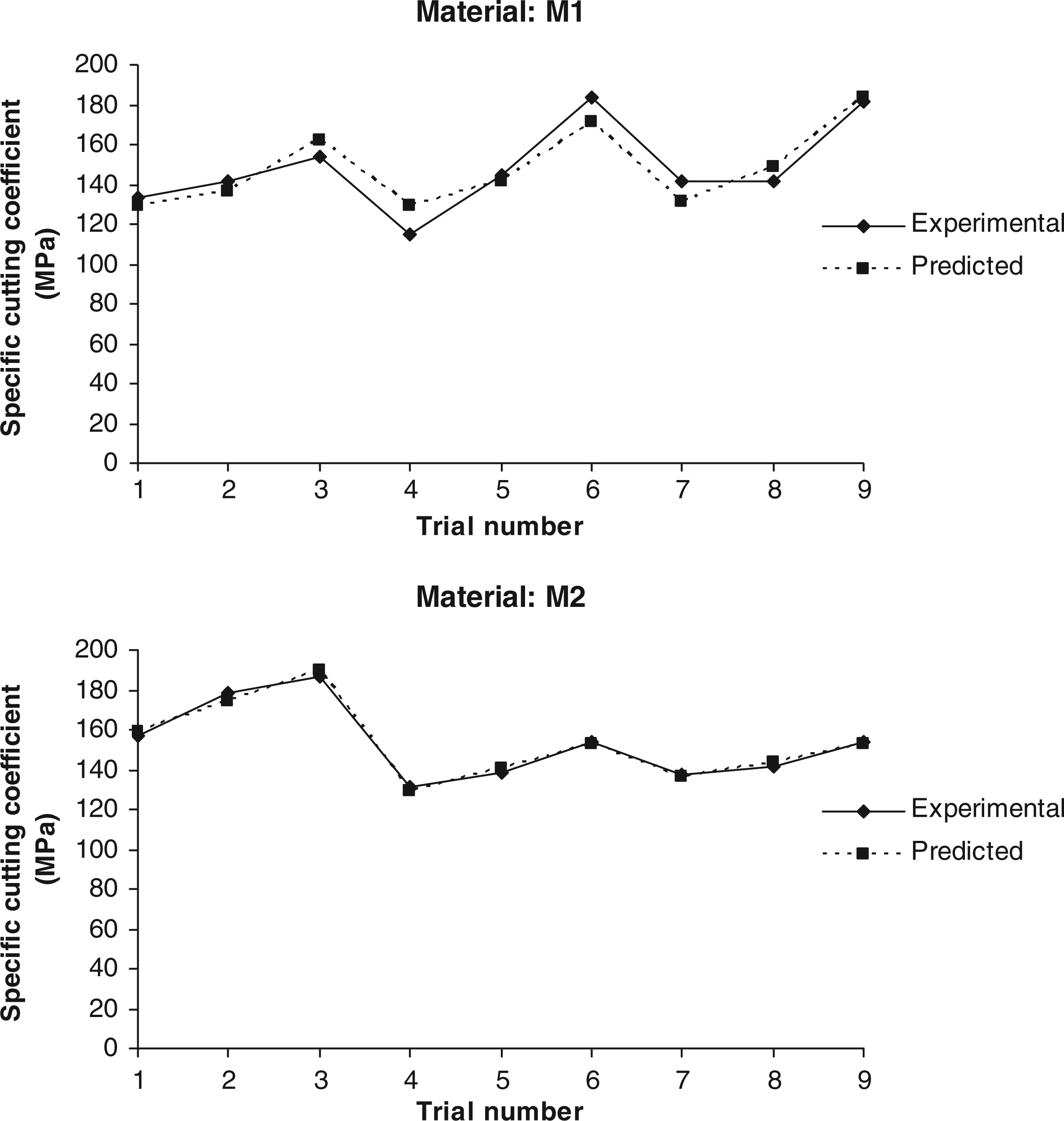
The prediction error of the proposed models is given in Table 5 and found to be within 6%. The comparison of the predicted and experimental values of thrust force (Ft), surface roughness of hole (Ra), and specific cutting coefficient related to thrust (Kt) for the experimental data of FFD during drilling of M1 and M2 materials is displayed in Figures 1–3, respectively. As seen from these figures, there exists a close relationship between the experimental and the predicted values and it has been also found that there are no abnormal variations between the experimental and the predicted values. Hence, the proposed RSM-based second-order models can be used for the prediction of machinability aspects.
Experimental and predicted values for thrust force. Experimental and predicted values for surface roughness of hole. Experimental and predicted values for specific cutting coefficient.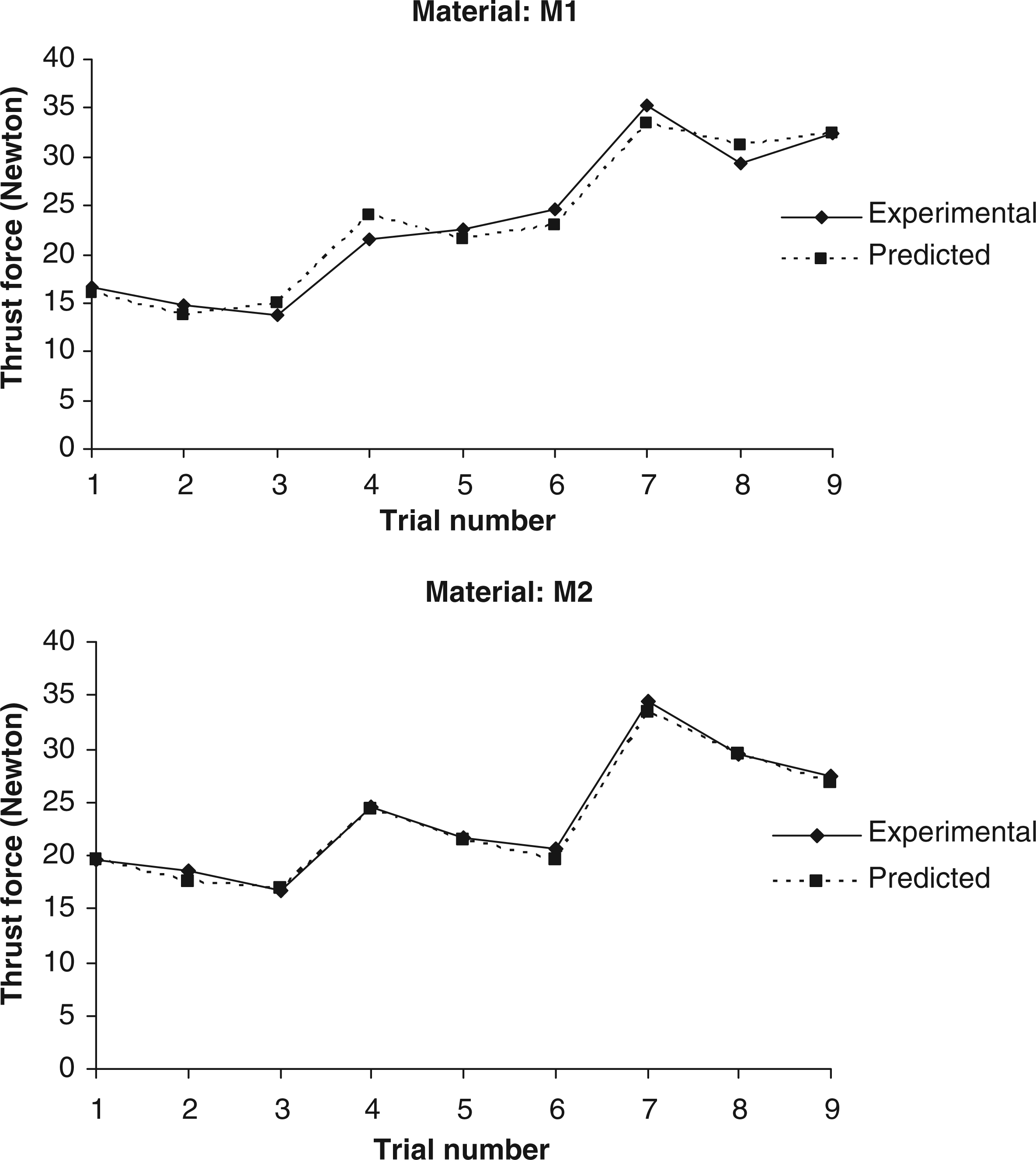
Parametric Analysis on Machinability Characteristics
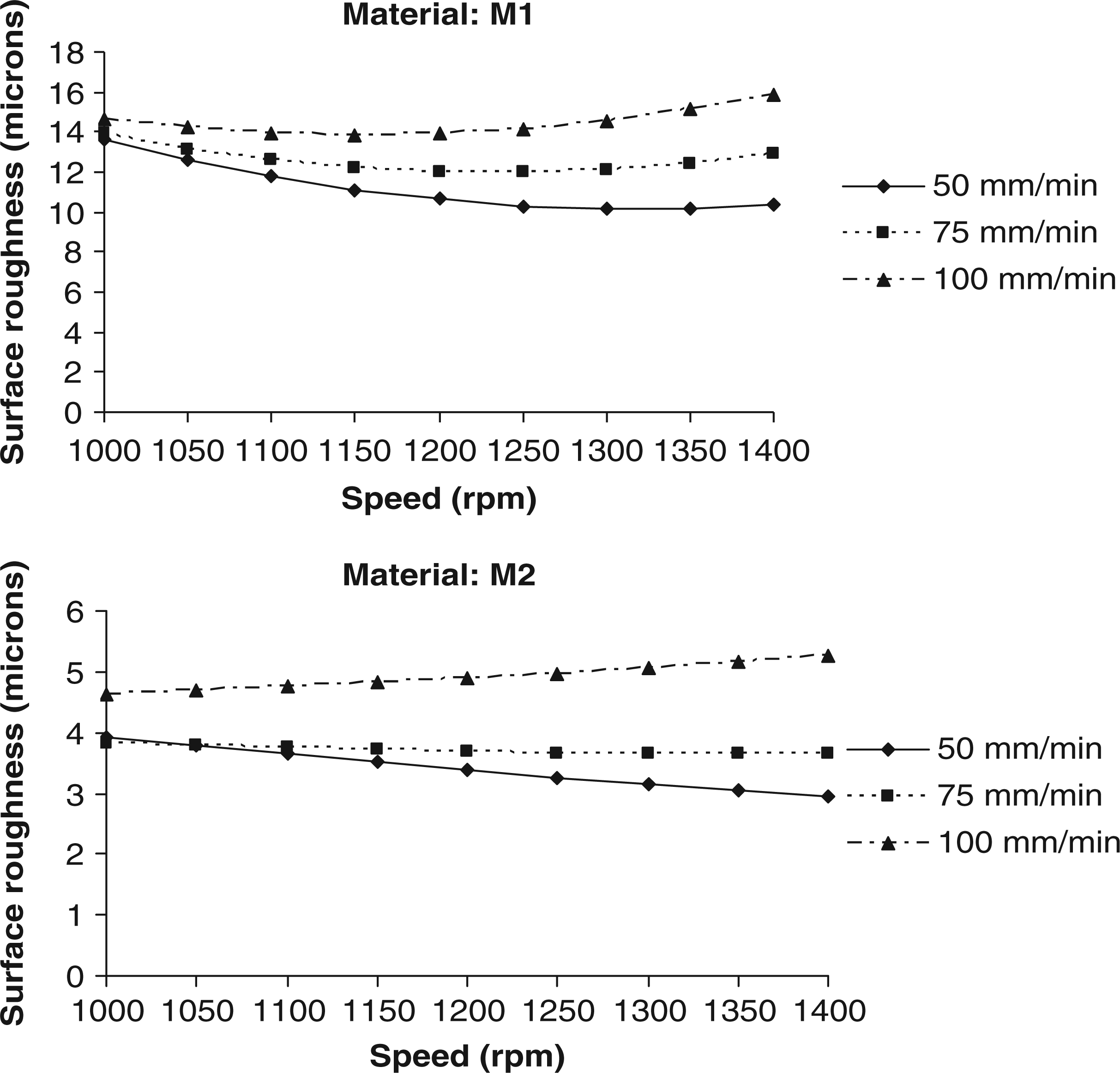
Equations (5)–(10) are used to predict the machinability aspects, namely, thrust force (Ft), surface roughness of hole (Ra), and specific cutting coefficient related to thrust (Kt) by substituting the values of spindle speed (N) and feed (f) within the ranges of the process parameters selected. The variations of the thrust force, hole surface roughness, and specific cutting coefficient related to thrust with respect to the cutting conditions are plotted for each of the work materials tested, as shown in Figures 4–6, respectively.
Effect spindle speed and feed on thrust force. Effect of spindle speed and feed on surface roughness of hole. Effect of spindle speed and feed on specific cutting coefficient.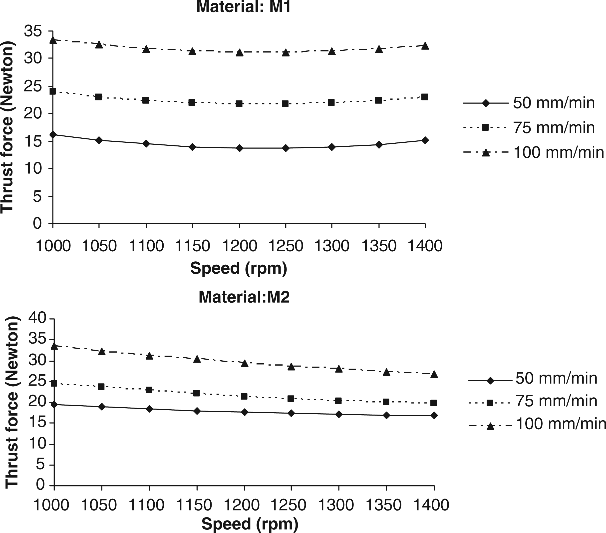
THRUST FORCE
Thrust force is the reaction force against the advancement of drill into the workpiece material. Figure 4 depicts the interaction effects of spindle speed and feed on thrust force during drilling of glass epoxy composite without the addition of filler (M1) and silicon carbide-filled glass epoxy composite (M2) workpiece materials. As seen from this figure, the thrust force increases with the increase in feed for a given value of spindle speed for both the materials tested. This is explained by the fact that, at low feed, there is a smaller resistance to drill in the direction of feed. On the other hand, at larger feed rates, the work material offers more resistance in cutting direction; thereby the increase in friction leads to higher thrust forces. Further, with the increase in feed rate, the contact area between the work material and drill increases and hence material removal rate (MRR) increases, which in turn increases the thrust force. In addition, at higher feed rates, there is a higher impact of cutting edges against the fibers as well as an increase in self-generated feed angle, which considerably reduces the relief angle and thereby rubbing takes place against the work material resulting in higher thrust forces.
For a given feed, the thrust force is more or less same with the increase in spindle speed and less sensitive to feed variations for the drilling of glass epoxy composite material without filler (M1). On the other hand, the thrust force has a tendency to decrease with the increase in spindle speed for a given value of feed during drilling of silicon carbide-filled glass epoxy composite material (M2). The decrease in thrust force with the increase in speed is attributed to the reduced work-tool contact length. Further, it is also observed that the thrust force sharply decreases with the increase in spindle speed for higher feed rate (100 mm/min) compared to smaller feed rate (50 mm/min).
Figure 4 also indicates that the thrust force is slightly less sensitive to variations in feed at lower values of spindle speed compared to higher values of spindle speed for M2 material. It is also revealed from this figure that, except for lower feed value (50 mm/min), the thrust force requirement for M2 material is less compared to M1 material irrespective of the spindle speed specified. During drilling of silicon carbide-filled glass epoxy composite material (M2), as and when the drill advances, the interfacial bond between the silicon carbide particle present under the lip area and matrix material weakens before the epoxy material yields and the cracks are initiated at these points. These cracks propagate and reach the edges of the drilled hole, leading to a reduced uncut material without bending and hence the reduced thrust. At higher feed values, the thrust force is increased due to less reduction in interfacial bond strength between silicon carbide particle and matrix material. Hence, this investigation reveals that the silicon carbide-filled glass epoxy composite (M2) is easier to drill compared to glass epoxy composite without the addition of filler (M1). The lower thrust forces also imply slower drill wear as the magnitudes of thrust forces are expected to relate strongly with tool wear rate.
SURFACE ROUGHNESS
The surface roughness plays a major role in determining the machining accuracy. The variation of drilled hole surface roughness in relation to cutting conditions is illustrated in Figure 5. It is observed that the surface roughness decreases with the increase in speed and with further increase in feed, the roughness increases for both the materials tested. With low feed and high speed, the surface roughness decreases for both the composite materials tested. This is due to the fact that, as explained in the previous section, the thrust force increases with the increase in feed and hence poor surface finish. However, with the increase in speed, temperature increases at the cutting zone of drill that leads to softening of work material, which in turn reduces the surface roughness.
Figure 5 also reveals that the surface roughness is highly sensitive to variations in feed at higher values of speed compared to lower values of speed for both the composite materials. For any given combination of speed and feed, the surface roughness values of silicon carbide-filled glass epoxy composite material (M2) are less compared to glass epoxy composite without the addition of filler (M1). The possible reason might be the burnishing and honing effect produced by the trapped silicon carbide between drill and hole with the increase in cutting speed. However, as the feed increases, the contact time between drill and workpiece decreases, which in turn reduces the burnishing effect. During drilling of these materials, the silicon carbide is sheared off due to increased hardness of carbide drill leading to reduced surface roughness. Further, during drilling, the matrix is getting well spread with lesser fiber getting exposed and breakage of glass fiber takes place, which is attributed to the extensive loss of the material due to fragmentation of glass fiber and their detachment from the test material due to the non-availability of a medium to hold them. The silicon carbide particles, which are highly brittle in nature, will be crushed into smaller particles during drilling especially at higher speeds with lower feed rates and hence reduced surface roughness. Hence, from the machining point of view, silicon carbide-filled glass epoxy composite material (M2) provides a better surface finish when compared to glass epoxy composite without the addition of filler (M1).
As can be seen from Figure 5, the surface roughness exhibits linear behavior with feed and speed combination for M2 material, whereas the behavior is non-linear in the case of M1 material. During drilling of glass epoxy composite without the addition of filler (M1), for both the low (50 mm/min) and medium (75 mm/min) feed rate values, the surface roughness decreases with the increase in speeds up to 1250 rpm and the surface roughness increases beyond 1250 rpm. On the other hand, for a higher value of feed rate (100 mm/min), the surface roughness is more or less remains same up to 1150 rpm and increases further beyond 1150 rpm. In the case of silicon carbide-filled glass epoxy composite material (M2) drilling, the surface roughness sharply decreases with the increase in speed for a lower feed rate value of 50 mm/min, whereas the roughness more or less remains constant irrespective of the speed for a medium feed rate of 75 mm/min. On the other hand, the surface roughness continuously increases with the increase in speed for a higher value of feed rate (100 mm/min).
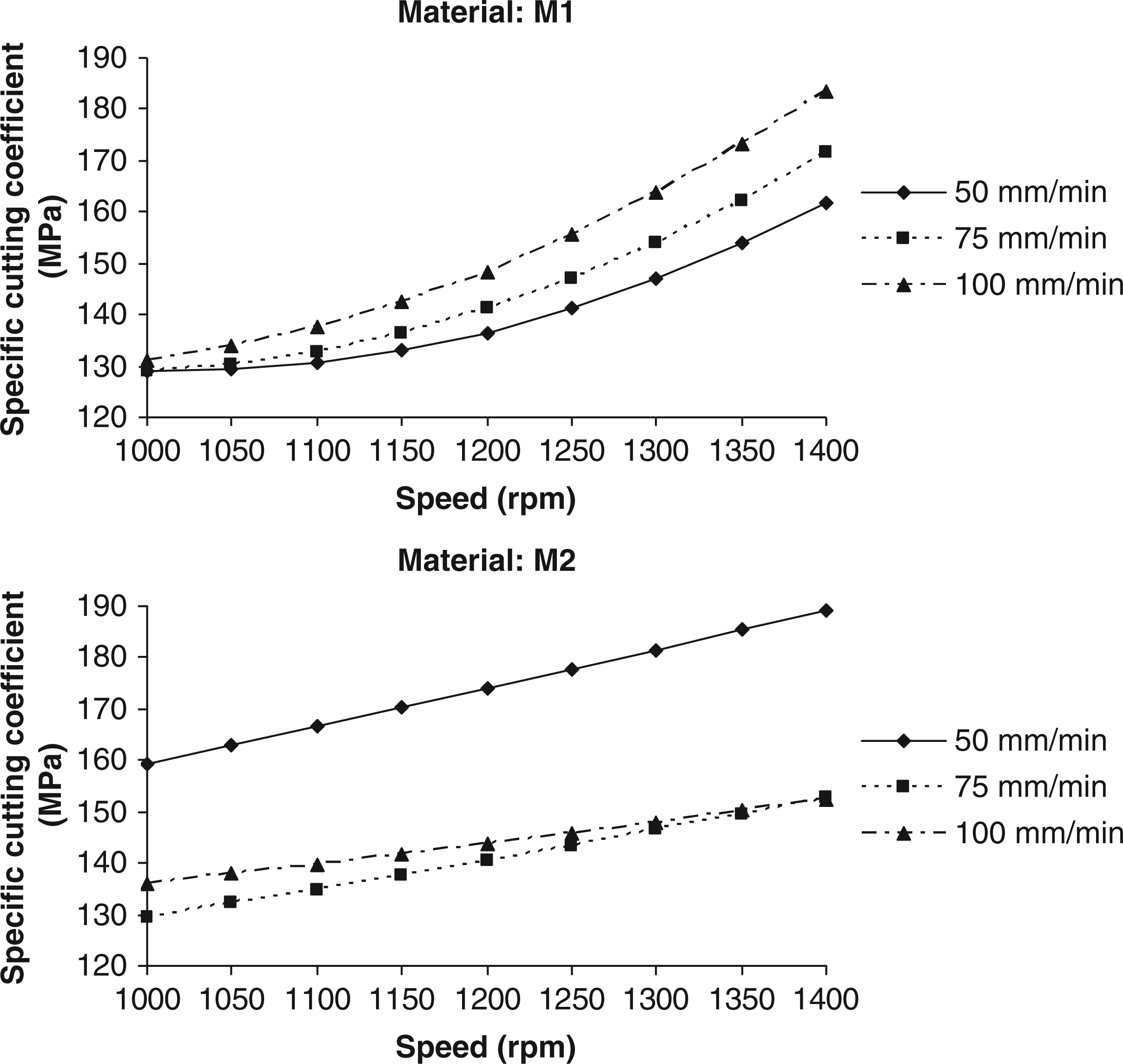
SPECIFIC CUTTING COEFFICIENT
The variation of specific cutting coefficient with speed for different values of feed is presented in Figure 6. It is observed that the specific cutting coefficient increases nonlinearly with the increase in speed for any given value of feed during drilling of glass epoxy composite without the addition of filler (M1) material. With the further increase in feed, the specific cutting coefficient has a tendency to increase with the speed. However, specific cutting coefficient is highly sensitive to feed at higher speed values compared to feed at smaller speed values. It is also revealed from this figure that specific cutting coefficient is found to be minimal for a combination of low value of speed (1000 rpm) and medium value of feed (75 mm/min) for the drilling of glass epoxy composite without the addition of filler (M1) material.
As seen from Figure 6, the specific cutting coefficient linearly increases with increase in speed during drilling of silicon carbide-filled glass epoxy composite (M2) material irrespective of feed. However, it is observed that this effect is more predominant for a low feed rate value of 50 mm/min compared to medium (75 mm/min) and high (100 mm/min) feed values. It is also found that the interaction effects due to speed and feed on specific cutting coefficient appear to be negligible for medium and high feed rate values. For a low feed rate value of 50 mm/min, the specific cutting coefficient is more for all values of speed compared to medium and high feeds for the drilling of silicon carbide-filled glass epoxy composite (M2) material. The low value of feed rate indicates that shear model could not fit the chip formation process adequately as the material is subjected to lower strain rates and hence the specific cutting coefficient tends to increase. On the other hand, at higher feed rates the number of fibers to be sheared will be reduced and hence decrease in specific cutting coefficient. Figure 6 also indicates that the requirement of specific cutting coefficient is less for a combination of 1000 rpm (low speed) and 75 mm/min (medium feed) for the drilling of silicon carbide-filled glass epoxy composite.
Some of the results of our analysis have been compared with the results reported in the previous works on the drilling of composites. Davim and Baptista [31] and Davim [41] performed drilling experiments on MMC. They observed that feed and cutting speed have major roles in controlling the surface roughness during drilling. Davim and Baptista [31] obtained the best surface finish with a feed rate of 0.1 mm/rev for a lower cutting speed of 30 m/min, while the worst finish was obtained for the intermediate cutting speed of 40 m/min. In our investigations also, we found that low feed values are necessary for minimizing both the thrust force and surface roughness. However, in our case, the surface roughness decreases with the increase in speed and with the further increase in feed, the surface roughness increases for both the composite materials tested.
The influence of different cutting conditions on the drilling of hybrid MMC was investigated experimentally by Basavarappa et al. [43,44]. Basavarappa et al. [43] found that the surface roughness decreases with the increase in cutting speed and increases with the increase in feed rate, which is similar to the results obtained by Basavarappa et al. [44]. Our study also supports these research findings. The experimental results analyzed by Basavarappa et al. [44] indicated that the feed has significant effect in reducing the thrust force and inclusion of graphite as an additional reinforcement in Al/SiCp-reinforced composite also reduces the thrust force. Their study also revealed that graphitic composites exhibit lesser thrust force and higher surface roughness. The reduced thrust is mainly due to solid lubricating property of the graphite and higher surface roughness is due to the pullout of graphite from the surface. Our study also suggested that the silicon carbide-filled glass epoxy composite is easier to drill and provides better surface finish compared to glass epoxy composite without the addition of filler.
The investigations carried out by Basavarappa et al. [46] on the drilling of SiCp and SiCp–graphitic-reinforced composites revealed that feed rate is the main factor, which influences the thrust force, while the surface finish increases with increase in cutting speed but decreases with increase in feed rate. Ramulu et al. [42] also found that regardless of the tool material and work material, the thrust force is highly dependent on feed rate, while the cutting speed was found to have insignificant influence on the degree of drilling forces. But our study does not support the findings of Ramulu et al. [42] with regard to the influence of cutting speed on thrust force. In our case, the thrust force increases with the increase in feed for a specified value of spindle speed and is less sensitive to feed variations for the drilling of glass epoxy composite material without filler. On the other hand, the thrust force decreases with the increase in spindle speed for a given value of feed during drilling of silicon carbide-filled glass epoxy composite material. However, the surface roughness is more sensitive to variations in feed at higher values of cutting speed compared to lower values of speed for both the composite materials tested. However, the effect of cutting conditions on specific cutting coefficient during drilling of the composites was not considered in any one of the previous studies.
From the above discussions on parametric analysis of machinability aspects, it is seen that thrust force, surface roughness, and specific cutting coefficient depend on combination of speed and feed for the drilling of glass epoxy composite without the addition of filler (M1) and silicon carbide-filled glass epoxy composite (M2) workpiece materials. The investigative study also indicates that the silicon carbide-filled glass epoxy composite exhibits better machinability compared to glass epoxy composite without the addition of filler. Although it is desirable to have minimum values of thrust force, surface roughness, and specific cutting coefficient, the requirement of cutting conditions is different for each of the machinability characteristics, which also depend on the type of the composite. In general, during drilling of thermoplastic materials, the heat will be generated due to the friction between the tool and the workpiece material. This heat will in turn soften the matrix materials and subsequently change the properties of the materials in the localized region.
CONCLUSIONS
The experimental investigations on the three aspects of machinability, namely, thrust force, surface roughness of hole, and specific cutting coefficient related to thrust during drilling of glass epoxy polymer matrix composites with and without the addition of silicon carbide filler are presented in this article. For analyzing the effects of speed and feed on machinability characteristics, the experiments were planned as per FFD to minimize the experiments. The second-order mathematical models of thrust force, surface roughness of hole, and specific cutting coefficient were developed using RSM. The adequacy of the developed machinability models was tested through the ANOVA. Based on the experimental results and subsequent analysis, the following conclusions are drawn within the ranges of the parameters selected.
The thrust force increases with the increase in feed for a specified value of spindle speed for both the composite materials tested. For a given feed, the thrust force is more or less the same with the increase in spindle speed and less sensitive to feed variations for the drilling of glass epoxy composite material without filler. On the other hand, the thrust force decreases with the increase in spindle speed for a given value of feed during drilling of silicon carbide-filled glass epoxy composite material. The thrust force is less sensitive to variations in feed at lower values of spindle speed compared to higher values of spindle speed for silicon carbide-filled glass epoxy composite material. The surface roughness decreases with the increase in speed and with further increase in feed the surface roughness increases for both the composite materials tested. The surface roughness is more sensitive to variations in feed at higher values of speed compared to lower values of speed for both the composite materials tested. The specific cutting coefficient increases with increase in feed for any given value of speed for the drilling of both the materials tested. The specific cutting coefficient is minimal at low values of speed and feed for the drilling of glass epoxy composite without the addition of filler material. On the other hand, the specific cutting coefficient is found to be minimal at low speed (1000 rpm) and medium feed value (75 mm/min). The silicon carbide-filled glass epoxy composite material provides better machinability compared to glass epoxy composite without the addition of filler.