
Abstract
In recent years, there is a growing interest in joining techniques for thermoplastic composites as an alternative to adhesive bonding. In this article, a fusion bonding process called hot-tool welding is investigated for this purpose and the used material is a carbon fabric reinforced polyphenylene sulphide. The welds are first observed through a microscope, after which the quality is experimentally assessed using a short three-point bending setup. A comparison is made between the welded specimens and the equivalent hot pressed specimens. It can be concluded that the hot-tool welding process is very promising for the welding of material under study and that the short three-point bending setup proves interesting for evaluating bonds between composite specimens.
INTRODUCTION
An ideal structure would be designed without joints, since joints are potential sources of weakness and additional weight. In practice, however, the maximum size of a component is generally limited by the manufacturing processes. Moreover, demands such as inspection, accessibility, repair, transportation, and assembly result in the fact that load-bearing joints cannot be avoided. This fact does not change when designing with fiber-reinforced composites; joints can be drastically reduced, but they will always be a part of a structure [1]. Well-established joining techniques for metallic structures are not directly applicable to composites. Typical problems when using mechanical fasteners include, among others: (i) stress concentrations created by the presence of holes and cut-outs; (ii) delaminations originating from the localised wear occurring during drilling; (iii) different thermal expansion of fasteners relative to the composite; (iv) creep of the composite when using bolted joints; (v) extensive time and labor requirements of hole drilling [2]. Adhesive bonding is inherently preferable to mechanical fastening because of the continuous connection, avoiding large stress concentrations induced by each discrete fastener hole. However, extensive surface preparation and long curing times make adhesive bonding labor intensive [3,4]. Moreover, the need for recyclability [5] incites more and more manufacturers to choose materials and bonding systems which allow for recycling, excluding most thermosetting composites and adhesives [6].
Therefore, in recent years, the interest is growing in welding processes for thermoplastic composites, since (i) thermoplastics are difficult to bond because of their chemical inertness and (ii) the welding processes can reduce overall manufacturing cost and are expected to replace traditional assembly methods, such as adhesive and solvent bonding, mechanical fastening, and co-consolidation bonding [7]. The fusion bonding of pure thermoplastics is already a well known and commonly applied production process, but the process parameters cannot be extrapolated to the welding of fiber-reinforced thermoplastics, since the reinforcement has a large influence: the material is no longer isotropic and heat conduction is influenced. In general, these fusion bonding techniques can be categorized in three groups [7]: (i) frictional welding, including ultrasonic welding [8–11]; (ii) electromagnetic welding, including resistance welding [1,12–20] and induction welding [21,22]; and (iii) thermal welding, including infrared welding [23] and hot-tool welding.
To determine the quality of the weld, quasi-static experiments till failure are considered. In general, there are various test setups available for examining the strength of adhesive bonds or the growth of delaminations [24,25], such as (a) pure Mode I crack-growth with the double cantilever beam (DCB), (b) pure Mode II crack-growth with the end notch flexure beam (ENF), (c) combined Mode I and II with the Mixed Mode Bending (MMB), and (d) a structural test with the lap shear strength test (LSS). For evaluating the strength and the quality of the welds, the most commonly chosen experimental setups are the LSS [1,10,14–16] and DCB [14,15,23]. These methods give relevant information about the quality of the weld and are also quite useful for comparative studies [12]. With respect to the (finite element) modelling, a lot of attention is given on the modelling of the fusion bonding process itself [2], meaning that heat transfer, consolidation, and crystallization of the thermoplastic are considered [11,18–20,26].
In this article, the hot-tool welding process is considered as fusion bonding technique for a carbon fiber reinforced polyphenylene sulphide. This technique has some interesting advantages, for instance: dissimilar thermoplastics can be welded, the temperature of the molten interfaces can be accurately controlled, surface inaccuracies can be taken into account during the process, and it can handle complex geometries [7]. Furthermore, it is a relatively cheap process, since it does not require expensive machinery, as is the case for friction and ultrasonic welding [2,7]. A disadvantage is that the thermoplastic polymer often tends to stick to the hot-tool, in stead of; so special attention has to be paid to this aspect.
To evaluate the quality of the weld, a short-beam bending test, as described in the ASTM D2344/D 2344 M ‘Standard Test Method for Short-Beam Strength of Polymer Matrix Composite Materials and Their Laminates’ is considered. This test has the advantage that it requires a lot less material than for the lap shear or mode I DCB test and it is a very simple test; force and displacement give plenty of information.
In the next paragraph, the used materials and methods are discussed. This is followed by an overview of the experiments, and finally, some conclusions are drawn.
MATERIALS AND METHODS
Composite Material
The material under study was a carbon fiber-reinforced polyphenylene sulphide (PPS), called CETEX. This material is supplied to us by Ten Cate. The fiber type is the carbon fiber T300J 3 K and the weaving pattern is a 5-harness satin weave with a mass per surface unit of 286 g/m2. The 5-harness satin weave is a fabric with high strength in both directions and excellent bending properties.
The carbon PPS plates were hot pressed, and two stacking sequences were considered for this study: (i) [(0°,90°)]4s, which is used to produce the welded joints and (ii) [(0°,90°)4, (90°,0°)4]s which is used as a benchmark to assess the quality of the welds. In both cases, (0°,90°) represents one layer of fabric, so the first sequence consists of eight layers, whereas the second consists of 16 layers.
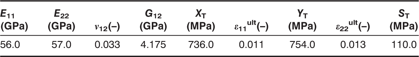
Elastic and strength properties of the CETEX® material.
The test coupons were sawn with a water-cooled diamond saw; the dimensions of the specimens are shown in Figure 1. The dimensions of the welded specimen are chosen so that from each weld, three bending coupons can be cut.
Dimensions of the used specimens in millimetres: (a) bending specimen, (b) welded specimen Rx.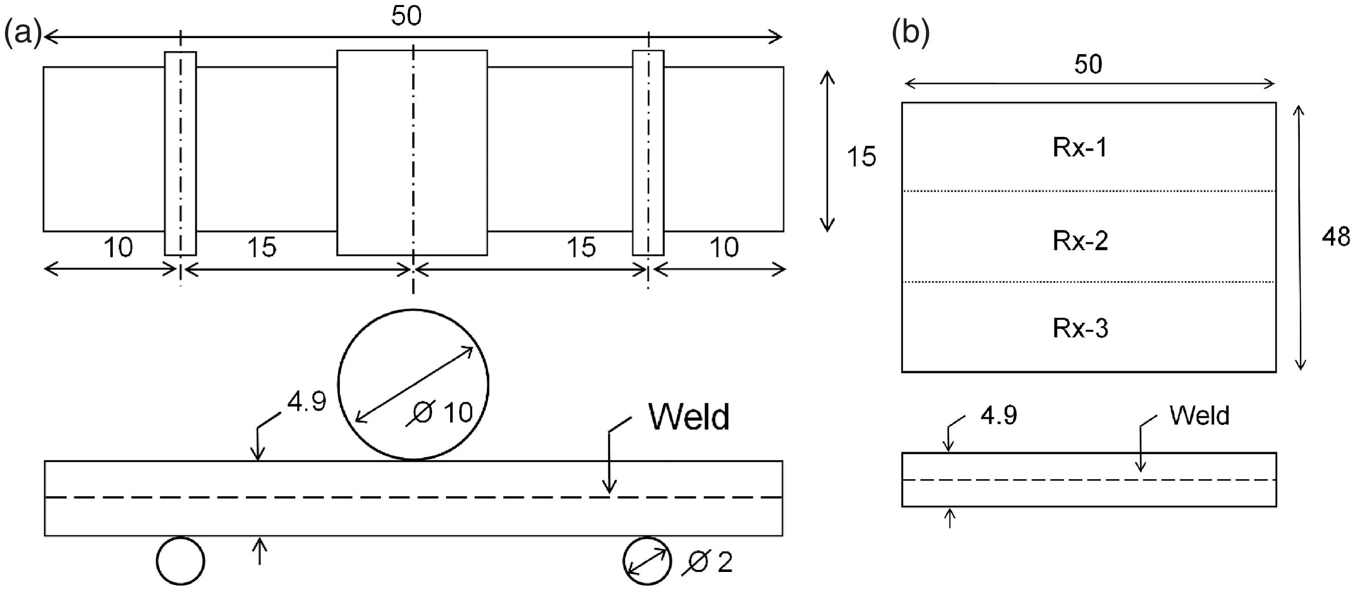
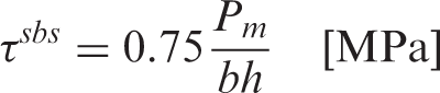
To evaluate the strength, the short beam strength, as mentioned in the ASTM D2344/D 2344 M ‘Standard Test Method for Short-Beam Strength of Polymer Matrix Composite Materials and Their Laminates’ is calculated using Equation (1):
Equipment
The welding process was performed on a servo-hydraulic INSTRON 8801 tensile testing machine with a FastTrack 8800 digital controller and a load cell of ±5 kN.
All bending tests were performed on an electromechanical INSTRON 5800 R tensile testing machine with a FastTrack 8800 digital controller and a load cell of ±10 kN. The quasi-static bending tests were displacement-controlled with a speed of 2 mm/min.
For the registration of the data, a combination of a National Instruments NI-USB-6251 data acquisition card and the SCB-68 pin shielded connecter were used. The load and displacement, given by the FastTrack controller, as well as the temperature from the thermocouple were sampled on the same time basis.
EXPERIMENTS AND DISCUSSION
Welding Process
The fusion bonding process of choice is the ‘hot-tool welding’, of which the principle is illustrated in Figure 2(a). The two surfaces to be welded are pushed against a heating element (step 1) and once the temperature is high enough, the two parts are pressed against one another with sufficient force (step 2). If necessary, extra filling material (thermoplastic sheets, reinforcement) can be added to the weld, but this was not considered for this research. The ‘hot-tool’ is shown in Figure 2(b). The surfaces of the parts to be welded make contact with the top and bottom contact plate respectively and the heat is generated using a heating resistor. A thermocouple is embedded near the surface of the hot-tool to control the temperature of the unit. The power of the resistor is controlled with the separate control unit, which takes the temperature into account. With this device, an area of 100 mm × 100 mm can be heated. For this research, an extra plate was added on top of the welding device, so that a contact area of 50 mm wide can be heated, in order to produce the specimens illustrated in Figure 1(b). One of the disadvantages of hot-tool welding is that some thermoplastic material remains on the hot-tool. By using this plate, it is easier to keep the hot-tool clean and a number of films can be wrapped around this plate to avoid the sticking. Both TEFLON and KAPTON were assessed for this purpose, since these materials survive at the melting temperature of PPS, which is 280°C, but eventually, the best method was using no film at all and making contact between the steel plate and the composite. PPS always stuck to the film, but the film itself made the removing of the hot-tool prior to the consolidation phase a lot more cumbersome.
The ‘hot-tool’ welding process and setup: (a) principle of hot-tool welding, (b) the actual setup.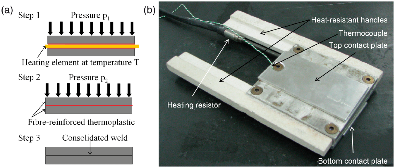
The actual setup is illustrated in Figure 3(a). The two specimens are attached with double-sided tape to the top and bottom metal stamp to prevent the specimens from sticking to the hot-tool upon removal. For this picture, the lower specimen is taken for visibility.
Illustration of the heating step: (a) contact-heating the specimens, (b) contactless-heating the specimens.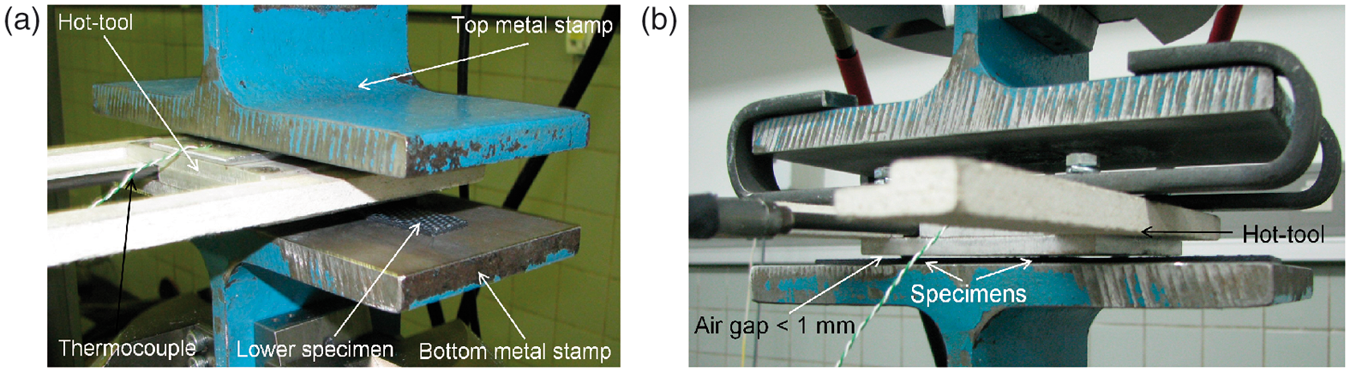
It was also assessed whether the PPS could be melted without being in contact with the hot-tool, by positioning the hot-tool less than 1 mm above the surfaces of the two parts (Figure 3(b)). As such, the PPS would never stick to the hot-tool. However, the heat generated by the hot-tool proved insufficient for melting the PPS, even after 10 min of exposure. Possibly, due to the very good heat conduction of the carbon fibers and the metal stamps, the surface temperature could not exceed the melting temperature of the matrix.
Once the optimal contact-pressure range has been determined, a stand alone welding apparatus will be developed, but for this research, a servo-hydraulic INSTRON 8801 tensile machine was used with a 5 kN load cell to apply the pressure during welding and consolidation. During the welding phase, one can choose to hold the contact pressure constant or to press down until the weld has a certain thickness. For this study, the contact pressure was increased to the desired value and then the displacement was kept constant. Figure 4 illustrates the evolution of the contact pressure and the temperature during welding. The specimen was heated for about 80 s at an average temperature of 305°C. The temperature was set at 310°C but because of the high thermal conductivity of carbon, a lot of heat was dissipated to the surroundings and to the tensile machine. Since the temperature of the hot-tool is monitored, only the evolution of the temperature during the heating phase is relevant.
Illustration of the temperature and the welding pressure during the welding process.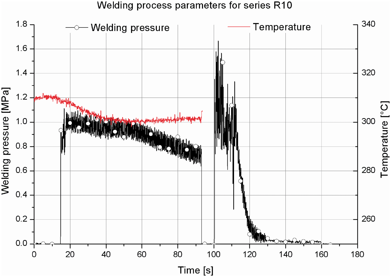
There is some scatter on the contact pressure, since it is quite difficult to maintain a constant load, even in load-controlled mode. The decrease in contact pressure during consolidation is due to the fact that the pressure pushes the liquid PPS out of the weld. The specimen is removed once the weld is fully solidified. As can be seen, the change-over time, meaning the time between the end of heating and the start of the part mating, is about 7 s.
Nondestructive Evaluation
In order to investigate the quality of the weld, some of the bending specimens were polished and investigated under the microscope. Also, after failure, some microscopic pictures were taken to see where and how the fracture occurred.
Figure 5 shows an image of a not so successful weld. In this picture, an area can be seen were there is no PPS between the top and bottom specimen. Possible reasons may be that there was insufficient heating at that location, that the matrix stuck to the hot-tool rather than to the fibers, or that insufficient pressure was applied.
Microscopic image of a bad weld. An area with no PPS is clearly visible.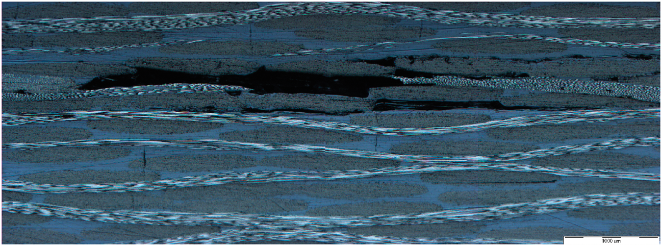
Figure 6 on the other hand shows the entire cross section of a bending specimen with a successful weld. The 16 different layers can clearly be distinguished and the weld lies in the middle, between the 8th and 9th layer. At that location, two horizontal fiber bundles make contact, with only very limited PPS in between. However, this does not necessarily mean it will be an inferior bond. First of all, this contact will only occur in limited places, given the nature of the 5-harness weave; second, between the warp and weft yarns also, limited PPS is present, and third, mechanical anchoring of fiber-bundles may even increase the strength of the bond.
Microscopic image of a successful weld (specimen R14-1).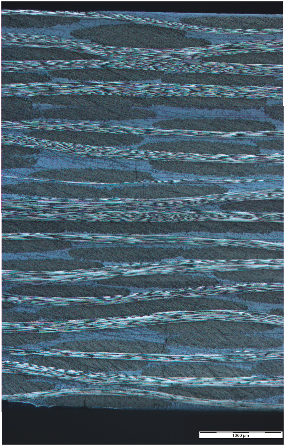
Short Beam Strength Experiments
In order to have some sort of reference value for the quality of the weld, two options were chosen. First, some specimens were adhesively bonded with adhesives that gave good results in the past [28]. Depending on the bonded materials, these adhesives should give an ultimate shear strength between 10 and 15 MPa. However, the most relevant would be to compare the behavior of the weld to the actual interlaminar behavior of the composite. As such, an extra plate of sixteen layers was produced using the same production parameters as for the [(0°,90°)]4s plate, which was used for the to be welded parts. In order to have the same stacking sequence as for the welded specimen, the sequence [(0°,90°)4, (90°,0°)4]s was chosen rather than [(0°,90°)]8s.
The results are shown in Figure 7, together with two bending tests on not bonded specimens. These are added to evaluate the bending stiffness when the bond has failed completely. For the adhesively bonded specimens, it can be clearly seen that once a load level around 1800–2000 N is reached, corresponding to a short-beam strength of 20.4 MPa, a very brittle interlaminar failure occurs and the force-displacement curve then follows the same trend as the curve from the unbonded specimens.
Bending experiments on adhesively bonded specimens.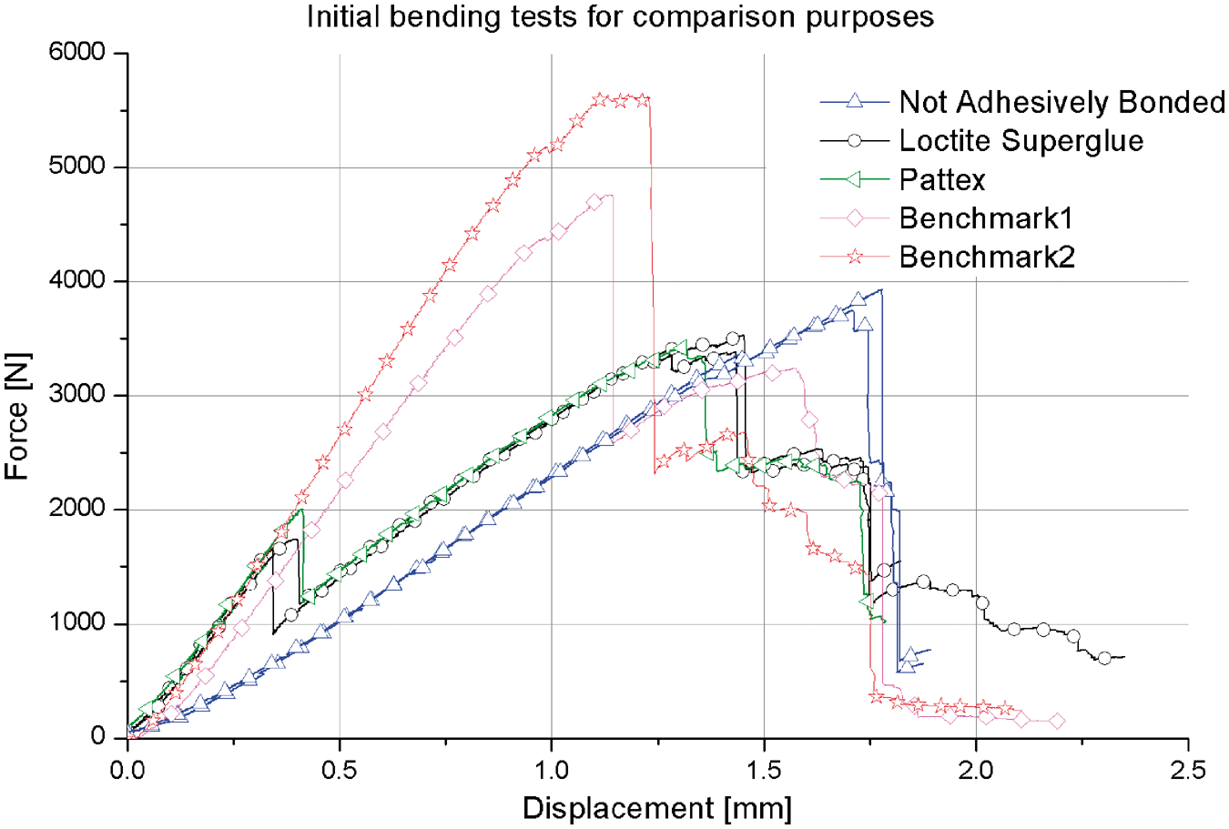
For the [(0°,90°)4, (90°,0°)4]s stacking sequence, which will be referred to as ‘benchmark’, two reproducible types of behavior were found; each of them is represented in Figure 7. Benchmark 2 yielded the highest failure load and failed purely due to bending loads, whereas Benchmark 1 first fails due to a delamination underneath the indenting roll, causing the significant drop in load which can be seen in Figure 7. Next, the specimen again carries load, but the bending stiffness is significantly reduced compared to the un-delaminated specimen, until it fails due to bending loads. With respect to the short beam strengths, for benchmark 1 and 2, an average value of 51.2 and 60.2 MPa respectively was determined.
The quality of the weld could also be assessed by the evolution of the tangent slope on the force displacement curves. Indeed, there is a significant difference in this parameter for bonded and unbonded specimens, meaning that when failure of the weld is not clearly visible on the specimen, it can be determined by the drop in slope from fully bonded to unbonded. Second, a weld of lesser quality, due to manufacturing parameters on one hand, or damage on the other hand, should be visible by the tangent slope. Indeed, as illustrated by Alfredsson et al. [29,30], changing the properties of the shear deformable layer (in this case, the weld) clearly has an influence on the compliance of the beam.
For the welded specimens, it is yet to be determined whether the bending stiffness will show a gradual decay or a sudden drop and whether its absolute value depends on the used welding parameters. The load-displacement of the failed bonded specimens lie a little higher than the unbonded specimen, but this is due to the fact that only half of the bond failed, between one outer support and the centre support.
A series of tests were conducted to evaluate the reproducibility of the quality of the weld along the length of the weld. From each welded specimen, as illustrated in Figure 1(b), three bending specimens are obtained. The results from one of those series, R10, are illustrated in Figure 8. As can be seen, the reproducibility is good, especially with respect to the bending stiffness. For this series, specimen R10-3 which was on the edge of the welding batch shows lower failure strength than the other two specimens. In general, it could be seen that specimen 3 showed a lower strength than the other two specimens. Closer examination of the welding setup showed that when welding pressure was applied, sometimes one of the stamps tilted a little, resulting in a lower pressure on that side of the specimen. This resulted in different consolidation parameters and consequently, different failure behavior. Therefore, for other experimental results depicted in this article, either specimen Rx-1 or Rx-2 from each series is illustrated as a representative for that welding process and the strength variation will be illustrated. It can also be noticed that the failure load is significantly higher than for the adhesively bonded specimens, illustrated in Figure 7, although it is lower than benchmark 2.
Bending tests on three specimens from one weld process.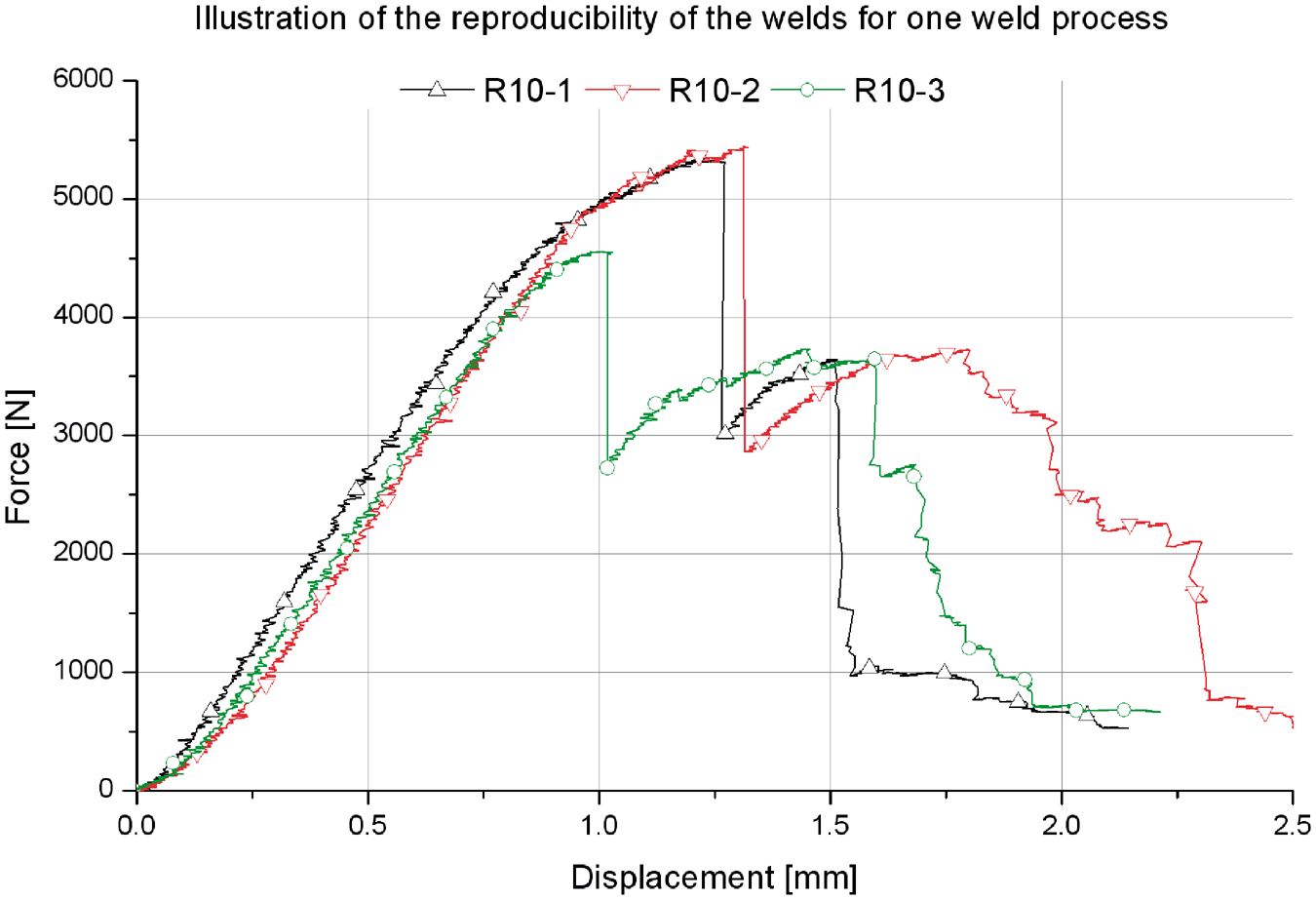
Figure 9 shows several bending experiments on specimens from different welding processes. As can be seen, the reproducibility of the bending stiffness is high. It should be noted that the bending stiffness does not show a significant dependence on the welding parameters. With respect to the failure force, this value of course depends on the welding parameters, but even for a not so successful weld (R4-1) the failure force is still significantly higher than for the adhesively bonded specimens. It can also be noticed that most specimens tend to follow the curve of two separate, not bonded specimens after initial failure, meaning that failure is still quite brittle, although specimen R14-1 shows a very progressive failure. In general, the failure modes depend on the quality of the weld. The highest quality first showed very small delaminations in the mid plane and then failed due to bending loads (series R14). The mid quality welds first showed larger delaminations in the mid plane compared to the best quality, and then still failed due to a combination of bending loads and delaminations whereas the worst quality welds, similar to the adhesively bonded joints, failed purely due to delamination of the mid plane. These also failed quite brittle.
Force–displacement curves for specimens from different welding processes.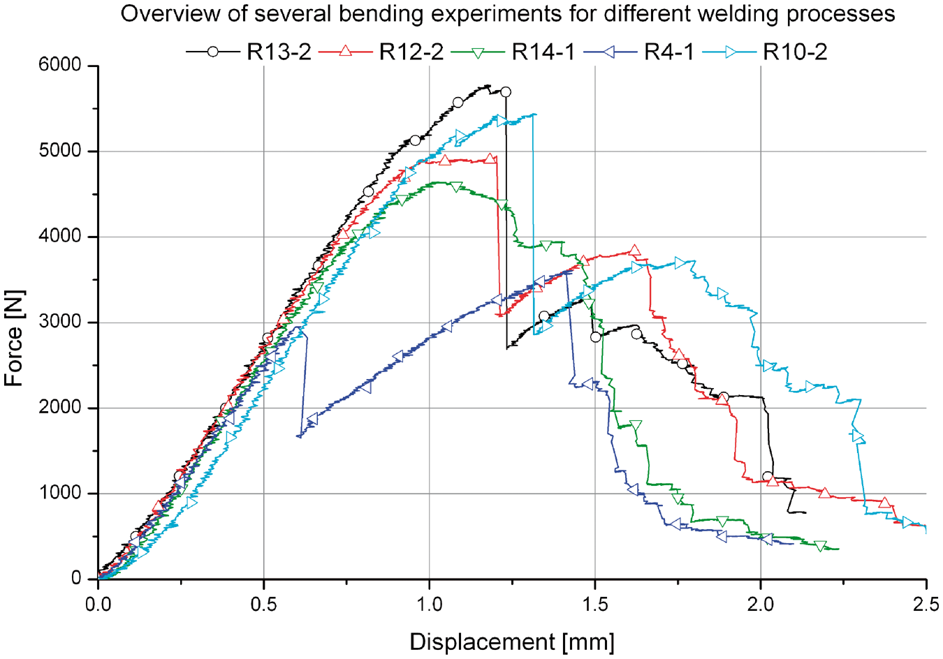
Overview of the welding parameters for the experiments shown in this article, together with the short-beam strength (Equation (1)).
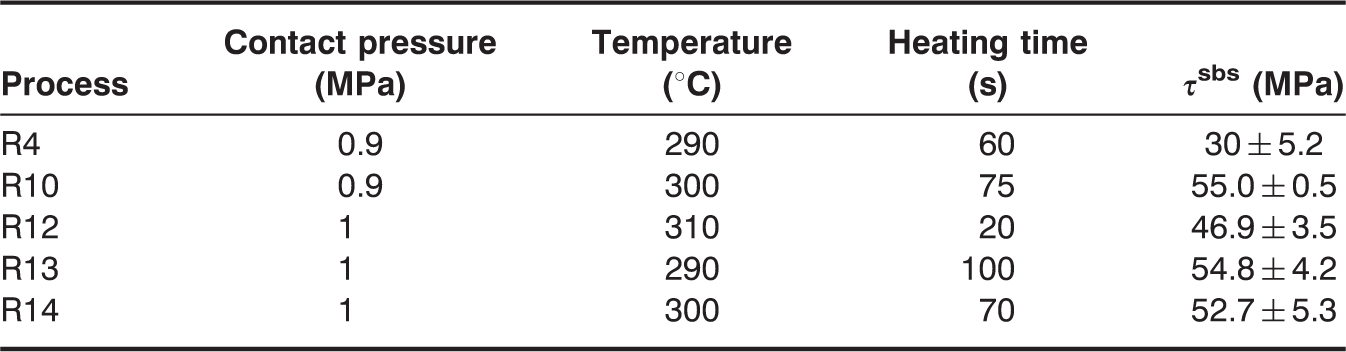
With respect to the temperature, the melting point of PPS is 280°C, so temperatures lower were not considered. A temperature higher than 310°C was too high; on some locations of the welded surface, the PPS started to burn whereas on other locations (for the same weld) the PPS had not even melted. This is caused by the fact that the two separate specimens were not flat, but showed a little warping. Therefore, some areas of the plate made contact with the hot-tool whereas others did not. Using higher contact pressures would solve this problem, but then all liquid PPS is pushed out of the weld, so no joint can be formed. This would also occur at lower temperatures, but then the process time was long enough for the carbon fibers to conduct and distribute the heat evenly, so that the entire surface melted. Joints realized at these higher temperatures were, of course, inferior. For the successful welds (R10, R12, R13, and R14), an average short-beam strength of 52.4 MPa is achieved. The value of τsbs in Table 2 is the average value for the entire welding series.
Considering these values in comparison to the benchmarks, more specifically, benchmark 2 which failed under bending loads, rather than benchmark 1 which delaminated, it can be concluded that although the short beam strength is already quite high, the best weld has not yet been achieved. The main reason for this is that the combined effects of weld pressure, temperature, and time on interdiffusion and optimal crystallization have not yet been considered. This, however, can have a significant influence on the bond strength, which has already been documented in literature, both under isothermal as nonisothermal conditions [31–33].
All current welds were manufactured within the boundary conditions of the currently used hot-tool setup, where both the heating temperature and consolidation pressure can be controlled. However, a very important parameter for the crystallization, namely the cooling rate during consolidation, cannot yet be controlled, since the two metal stamps currently used (Figure 3(a)), are not equipped with a heating system. Of course, when designing the stand alone welding setup, extra precautions such as temperature controlled molds and an in situ temperature measurement, will be taken into account to achieve the optimal consolidation parameters for the PPS [34,35] and other thermoplastics.
Finally, Figure 10 shows the occurring delaminations after failure, in the vicinity of the central failure under the central roll for the same specimen as was illustrated in Figure 6. As can be seen, two delaminations are present: the expected crack in the weld, but also delaminations between the fourth and the fifth layer of the laminate, illustrating that the strength of the weld lies very near to the interlaminar shear strength of the laminate, since otherwise, only the central crack would be present. The latter was the case with the experiments where the two laminates were adhesively bonded. It can also be noticed that the central crack does not stay in the weld, but travels to the top layer of the bottom specimen. Furthermore, the crack does not travel between the two 0° fiber bundles which make contact, illustrating the strength of the bond when mechanical anchoring of fibers is present.
Illustration of the delaminations after failure (specimen R14-1).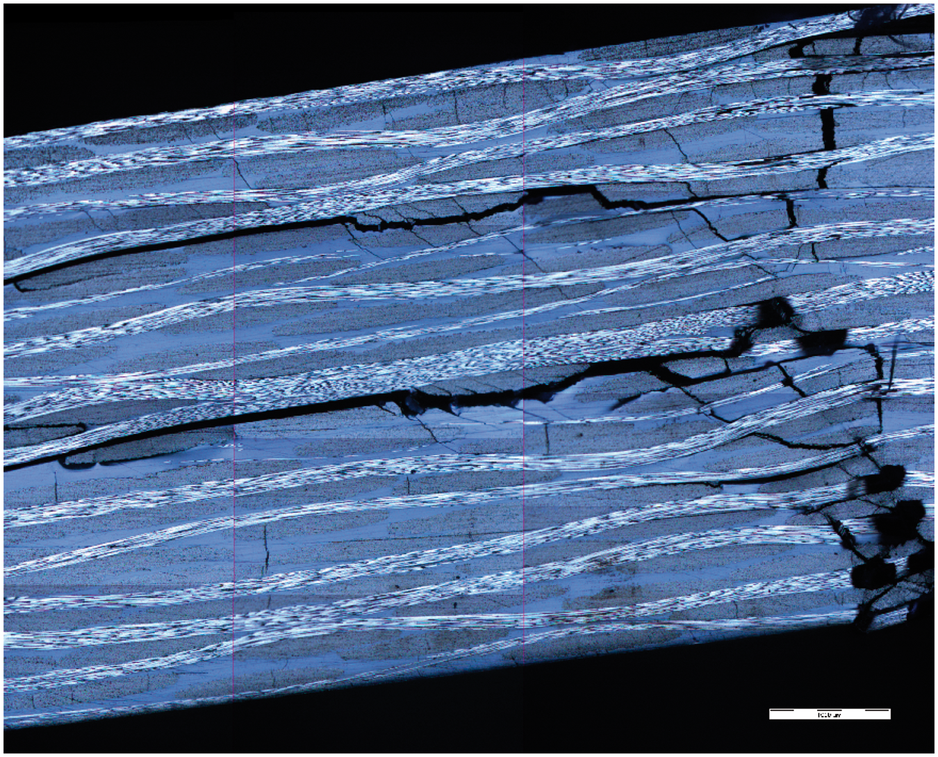
CONCLUSIONS
The hot-tool welding process is suited for welding the carbon-fabric reinforced PPS considered for this research. The interlaminar strength in a short three-point bending test is significantly higher than for adhesively bonded specimens and that the level of equivalent hot pressed plates is almost achieved. Furthermore, when observing the crack pattern of a welded specimen after bending failure, it was seen that not only the weld failed under interlaminar shear, but the composite laminate also showed delaminations. This means that the interlaminar strength of the weld is near to the interlaminar shear strength of the laminate.
For the welding parameters, a temperature between 295°C and 305°C in combination with a contact pressure of 1 MPa for about 60 s shows best results. Other temperatures resulted in either no melting or burning of the PPS. Lower contact pressures resulted in bad consolidation and higher pressure pushed out all PPS, so no bond could be formed. The time interval is not so narrow, but in general it may be concluded that within the specified range of temperature and pressure, the quality of the weld is mostly dependent on the experience of the operator. For the successful welds, an average short-beam strength of 52.4 MPa was achieved.