
Abstract
The use of carbon fibre (CF)-reinforced plastics has grown significantly in recent years, and new areas of application have been and are being developed. As a result, the amount of non-recyclable waste containing CF is also rising. There are currently no treatment methods for this type of waste. Within this project different approaches for the treatment of waste containing CF were investigated. Main subject of the research project were large-scale investigations on treatment possibilities and limits of waste containing CF in high temperature processes, with focus on the investigation of process-specific residues and possible fibre emission. The results showed that the two conventional thermal waste treatment concepts with grate and rotary kiln firing systems are not suitable for a complete oxidation of CFs due to the insufficient process conditions (temperature and dwell time). The CFs were mainly discharged via the bottom ash/slag. Due to the partial decomposition during thermal treatment, World Health Organization (WHO) fibres occurred in low concentrations. The tests run in the cement kiln plant have shown the necessity of comminution for waste containing CF. With respect to the short testing times and moderate quantities of inserted CF, a final evaluation of the suitability of this disposal path was not possible. The use of specially processed waste containing CF (carbon-fibre-reinforced plastic (CFRP) pellets) as a carbon substitute in calcium carbide production led to high carbon conversion rates. In the unburned furnace dust, which is marketed as a by-product of the process, CFs in relevant quantities could be detected.
Introduction
Carbon fibres (CFs) are fibres containing at least 92% carbon by weight (Klose, 2009) and are characterised by a very high ratio of tensile strength to modulus of elasticity. They differ significantly from other types of carbon allotrope fibres, with their carbon contents up to 100% by mass, such as carbon nanotubes or graphene. After being embedded in a shaping matrix, such as ceramic, metal, carbon-based or plastic, the resulting carbon-fibre-reinforced composites are high-performance materials, which are suitable for lightweight constructions. The matrix material with the highest market share (84.7 wt%; Sauer, 2019) is plastic and carbon-fibre-reinforced plastics (CFRP) are being used industrially since the 1970s, initially in the field of aviation.
In the recent years, CFRP have shown growth rates of over 10% per year (Sauer, 2019) but are still a niche application in comparison with other plastic products. For example, the current global demand for CFRP is around 128,500 t a−1 (Sauer, 2019), whereas the European demand for glass-fibre-reinforced plastics is 1.1 million t a−1 (Witten and Mathes, 2019), and the amount of plastics used in Germany alone is around 16.7 million t a−1 (Lindner and Schmitt, 2018).
Due to the increasing use of CFRP, the amount of waste generated also continues to grow. CFRP waste can be divided into production waste, and end-of-life waste. A further division into these two categories is also appropriate with regard to their waste management characteristics: In the field of aviation and wind energy, the proportion of CFRP is relatively high per unit of product manufactured. While in the automotive, sports equipment and construction sectors, the CFRP share is significantly lower and is distributed over a wide array of different products. For the purpose of material recovery, the recycling process would require specific organisational regulations for collection, sorting and processing of these carbon-fibre-containing waste (CFW). If CFRP is not collected separately, it cannot be detected and sorted even in state-of-the-art waste sorting plants. Consequently, the CFRP waste, together with other sorting residues from such sorting plants is fed into energy recovery processes (Handschick, 2018).
In current projects that deal with the treatment of CFW, the usual focus is on fibre recovery, since the production of CFs requires a high input of raw materials and energy. Various processes, such as pyrolysis or solvolysis, can be used for this purpose. For the use of recycled CFs in textile production, high purities and a suitable length distribution (Hofmann et al., 2019) are required, which inevitably leads to waste fractions of shortened, non-recyclable fibres. For such fractions, due to the high carbon and energy content of CFW, raw material (e.g. as carburising or reducing agent) or energy-recovery in industrial high-temperature processes seems reasonable.
Various studies on the thermal behaviour of CF can be found in literature. The main focus of research is the evaluation of the fibre behaviour in CF components during fires, for example in the aerospace industry (Babinsky and Musselmann, 1979; Bell, 1980; Bionetics Corp. Hampton, 1982; Gandhi and Lyon, 1998; GWP Gesellschaft für Werkstoffprüfung mbH, 2015; Lieberman et al., 1980; Max, 2015; Pride et al., 1980; Tadini et al., 2017; Tranchard et al., 2015). Another topic of research is the evaluation of material-specific behaviour during thermal stress (Feih and Mouritz, 2012; Mouritz and Gibson, 2006; Schartel et al., 2007; Tong et al., 2011; Wang et al., 2016). Furthermore, oxidation as a mean to improve surface properties during CF production has been evaluated (Chung, 1994; Donnet, 1998; Donnet and Chand, 1990; Fitzer, 1985).
The thermal behaviour of CF, however, is not described in detail, especially in matters of waste management. During CF oxidation, the following heterogeneous reaction occur primarily (Panerai et al., 2014; Yin et al., 1994):

The decomposition of fibres in an oxygen atmosphere is initially characterised by a decrease in fibre diameter. The mass loss starts at temperatures between 450 and 600°C (Bionetics Corp. Hampton, 1982; GWP Gesellschaft für Werkstoffprüfung mbH, 2015; Limburg et al., 2019; Mouritz and Gibson, 2006; Yin et al., 1994). The reaction first takes place at the fibre surface, and the active surface area mainly influences the reaction speed. In addition to the decrease in diameter, occasional pitting and pore formation are described. Pits and pores increase the reactive surface of the fibre. Oxidation can occur faster and spread deeper into the transverse profile of the fibre (Dhami et al., 1991; Kim et al., 2011). Research has shown that defects in the surface and layered structure support a fragmentation of fibres into smaller particles (splintering). This has been shown to predominantly affect areas of low crystal density (Chung, 1994; Donnet, 1998; Donnet and Chand, 1990; Fitzer, 1985). However, the matrix material in which the fibres are embedded can also inhibit the reactions by for example released gases (Eibl, 2015b; Park, 2015).
Incompletely decomposed fibres cause residues that can be exhausted from the furnace. Researchers of the U.S. Environmental Protection Agency have characterised these residues according to their dimensions (Bionetics Corp. Hampton, 1982):
Fibres longer than 1 mm
Fibres with a length between 50 µm and 1 mm
Fibres shorter than 50 µm with a reduced diameter below 4 µm
Different risk potentials for the above-mentioned groups have been determined. Fibre residues longer than 1 mm can cause defects in electric and electronic components by short circuits. An especially high-risk potential is posed by fibres shorter than 50 µm with reduced diameters below 4 µm. These dimensions are similar to the current World Health Organization (WHO) definition for cancer-causing fibres (lengths >5 µm with diameters <3 µm and length to diameter ratios larger than 1:3). Whether these fibres are a health hazard to humans is currently under research. In the past, the research was focused mainly on fibres that have been treated mechanically (Holt and Horne, 1978; Kehren et al., 2019; Martin et al., 1989; Mattenklott and Van Gelder, 2019; Mazumder et al., 1982; Schlagenhauf et al., 2015; Thomson et al., 1990; Wang et al., 2017). It is recommended for further investigations to focus on thermally treated fibre residues (Kehren et al., 2019; Stapf, 2019).
In the manufacturing processes of CFRP, the proportion of respirable CFs is typically in the range <0.1% by weight of the dust produced (Mattenklott and Van Gelder, 2019). Currently, no data were available on the formation of respirable CF fragments during the recycling of CF in high-temperature processes.
In conclusion, the existing publications show that the decomposition of CFs is dependent on various factors. However, deriving the necessary information for the layout of potential high-temperature processes with energy recovery, feedstock recycling is only possible to a limited extend. Examining the suitability of these processes for material and energy recovery was the key objective of the study presented here. Besides the process parameters, various aspects, such as the composition of the material, its thermal behaviour, and the available amounts of CFW, are relevant.
Experimental procedure
On the one hand, in order to improve the state of knowledge about the behaviour of CF and CFRP in high-temperature processes, and on the other hand, to investigate the suitability of various processes to treat CFRP waste, large-scale experiments were carried out, examining the utilisation of energy recovery and feedstock recycling. The investigations on energy recovery were carried out in a municipal solid waste incineration (MSWI) plant, a hazardous waste incineration plant (HWIP) and a cement kiln plant; the investigations on feedstock recycling were conducted using CFRP pellets as a substitute for coke in an electric arc furnace for the production of calcium carbide (CaC2). The following questions were to be examined in particular:
Which process-specific pre-treatment process is required for CFW?
Are there any restrictions or disruptions of control operation, such as impairments of the plant technology (e.g. electrostatic precipitator)?
Are the process parameters sufficient for a complete conversion of the CF?
Is there a release of fibres via the solid residues or via the products? If so, do they contain CFs with WHO geometry?
Are fibres released via the exhaust gas path? If so, do they meet WHO criteria?
Prior to the respective test campaigns, the CFW was prepared and characterised as described below.
Used waste types
Four different types of waste were used in the large-scale experiments, each with respect to the process-specific requirements (Figure 1). For the evaluation of the experiments, a detailed characterisation of the waste streams was carried out. During and after the preparation of the respective wastes, sampling and analysis were conducted, and the CF content was estimated. It was assumed that the CFs themselves contained neither ash nor volatiles.
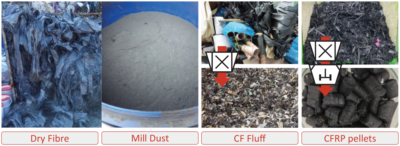
Carbon fibre (CF)-containing waste used in the large-scale experiments (production of CF fluff and CFRP pellets: input material at the top, after production at the bottom).
The Dry fibre waste showed little storage-related contamination. The material was crushed, sampled and analysed in the laboratory. Through measurement of the ash and volatile content (8.9 wt%), a CF content of 91.1 wt% (dry) was determined.
Mill dust was stored in closed drums. In addition to CF, the milling dust also contained parts of the plastic matrices. A total ash and volatile matter content of 44.4 wt% (dry) and a CF content of 55.6 wt% (dry) were determined.
CF fluff had a high content of accompanying materials, such as paper, cardboard, cartons and plastics. The sorted CF-rich fraction had high volatile content. The CF content was estimated to 39.3 wt% (dry). The CF fluff fractions for the MSWI and the cement kiln were analysed individually due to storage-related differences in the water content.
To produce CFRP pellets, CFRP production waste was first crushed and then pelletised with an addition of mixed-plastics waste. The initial CFRP content was 45 wt% (dry). Taking into account a total volatile and ash content of 50 wt% (dry), a resulting CF content of 22.5 wt% (dry) for the pellets was assumed.
Table 1 summarises the properties of the CFW.
Properties of the waste used.
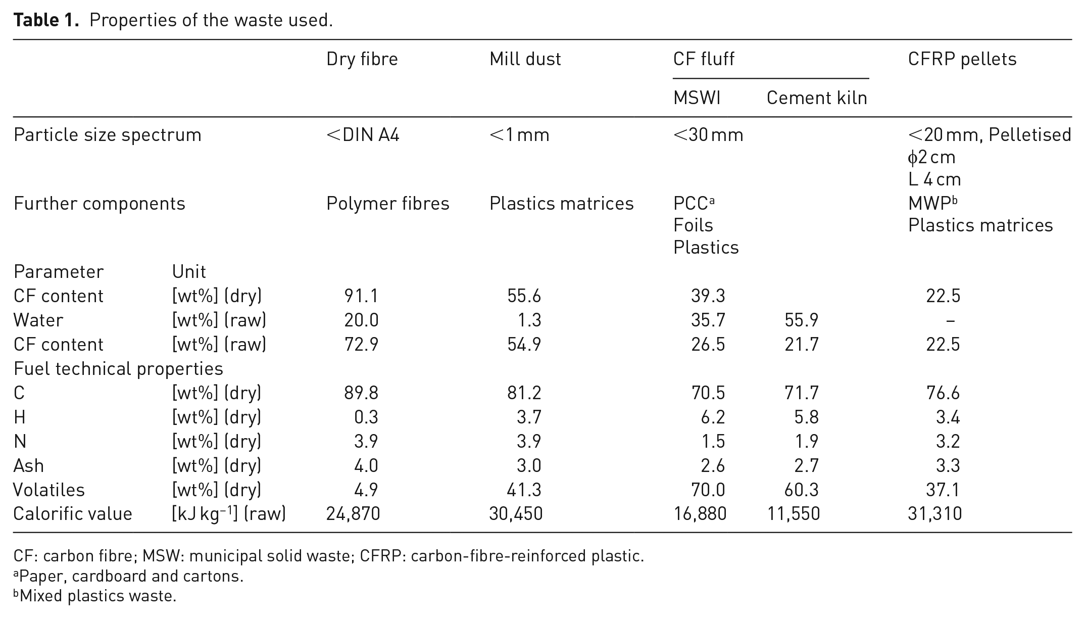
CF: carbon fibre; MSW: municipal solid waste; CFRP: carbon-fibre-reinforced plastic.
Paper, cardboard and cartons.
Mixed plastics waste.
Procedure
Although there have been no industrial-scale investigations for the treatment of CFW at high temperatures to date, the behaviour of new materials in high-temperature processes has already been investigated for various types of materials, such as composite-thermal-insulation systems (Dresch et al., 2015; Mark et al., 2015), chlorofluorocarbons (Aleksandrov et al., 2019; Rittmeyer et al., 1994) and nanomaterials (Baran and Quicker, 2017; Baumann et al., 2015; Börner et al., 2016; Hölemann et al., 2019; Walser and Gottschalk, 2014; Walser et al., 2012), within the framework of large-scale measurements, therefore, an orientation to their methodical procedure could be made.
The individual test campaigns for these materials included the determination of the baseline condition of the plant and the subsequent addition of the respective waste fraction over several hours. In the assessment of the thermally stable nanomaterials, the need for sufficient lead time for the application of waste became clear (Baran and Quicker, 2017; Walser and Gottschalk, 2014).
For the investigation of the behaviour of pre-treated CFW, the following test periods were defined:
Reference measurements before CFW addition (Reference)
Measurements during and directly following to the addition of CFW
Control measurements after the addition of CFW (Control)
During the reference phase, the status quo of the plant was taken up. This was intended to identify any diffuse-CFW that may already be introduced in the plants. In the test period ‘addition of CFW’, a defined mass flow of CFW was added to the plant. Sampling and monitoring started after an appropriate lead time in order to wait for stationary conditions for the measurements. The test period ‘control’ was intended to record possible memory effects within the plant.
Within the scope of the measurements, all process-specific products and residues were sampled and characterised. In addition, measurements were carried out at different points in the exhaust gas path using Particle Wire Mesh Method (PWMM) and gravimetric dust measurements. The procedure is explained in detail in the following section. Table 2 gives an overview of the performance of the individual test campaigns. Supporting Information A shows schematics of the plants examined and an overview of the measuring points.
Overview of large-scale test campaigns.
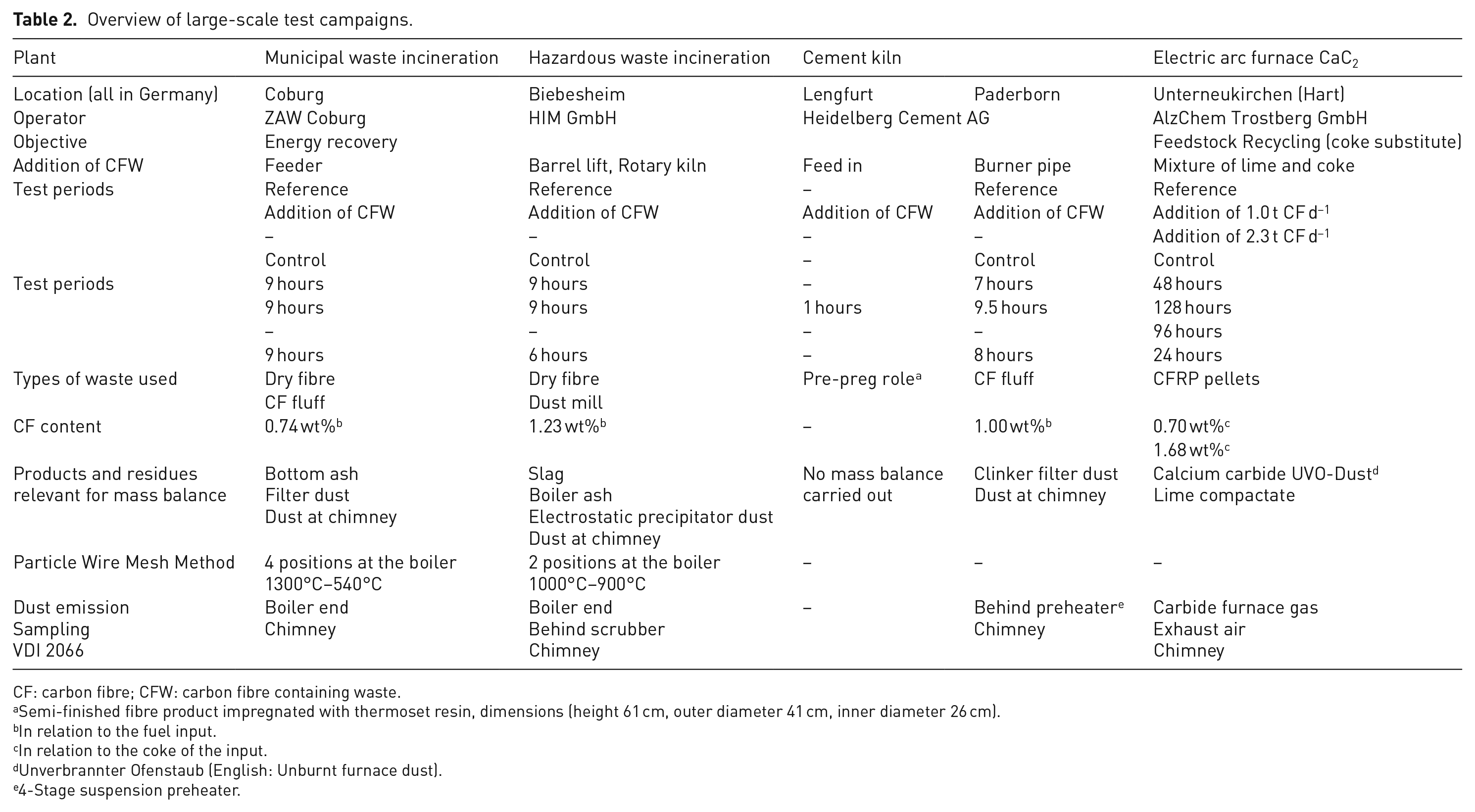
CF: carbon fibre; CFW: carbon fibre containing waste.
Semi-finished fibre product impregnated with thermoset resin, dimensions (height 61 cm, outer diameter 41 cm, inner diameter 26 cm).
In relation to the fuel input.
In relation to the coke of the input.
Unverbrannter Ofenstaub (English: Unburnt furnace dust).
4-Stage suspension preheater.
The conversion of CF is assessed by means of the recovery rate (RR). In a thermal process, CFs can be (i) converted, (ii) deposited within the plant or (iii) discharged. By considering a sufficient lead time, preferably stationary conditions shall be ensured so that the deposition quantity in the plant reaches an equilibrium. The proportion of undetected fibres shall be kept as low as possible by a suitable sampling and evaluation method. The recovery rate then corresponds to the discharged and detected CFs (
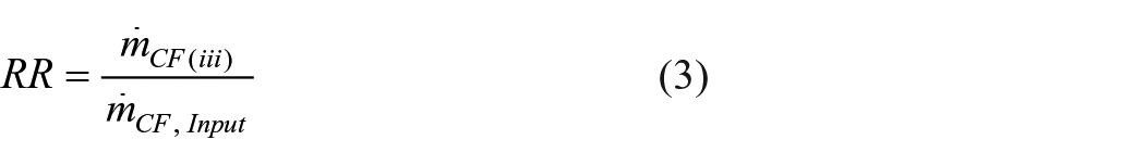
The conversion can be calculated from the recovery rate, neglecting fibre deposits in the plant or measurement uncertainties:

Methods
During the large-scale investigations, the samples were taken, prepared for fibre analysis and analysed according to the methodology described below.
Sampling and preparation of the solids
Sampling of process-specific products and residues were carried out at periodic intervals. The determination of the minimum quantity of sample material was based on the specifications of the Working Group of the Federal States on Waste guideline PN98 ‘Principles for taking samples from waste and deposited materials’ (Länderarbeitsgemeinschaft Abfall, 2002). From the partial samples, mixed samples were created for the respective test periods. For bottom ash and slag, the sampling model for acceptance tests of thermal waste treatment plants were used (see Supporting Information B) (Fachverband Anlagenbau Energie, Umwelt, Prozessenergie, 2013).
The samples taken were then analysed for their fibre content. In order to avoid possible impacts on fibre geometry, the material was not crushed but merely classified. The CF content was determined visually and gravimetrically for material >1 mm. The material <1 mm was examined via light microscopy (Keyence VHX 2000 with objective VH Z20T and Keyence VHX-5000 with objective VH Z500). For this purpose, the material was suspended in de-ionised water or ethanol and filtrated on plane filters. Sections of the filter surface were then evaluated according to the analytical method for the determination of alveolar fibres using Light Microscopy method BGI/GUV-I 505-31 (Deutsche Gesetzliche Unfallversicherung, 2013). Fibres with a curvature or a diameter or colour atypical to CF were not considered.
For the determination of the total CF content, CF contents cCF,i of the respective sieving fractions mi were aggregated according to the measured particle size distribution.

Sampling of the exhaust gas
During the large-scale tests, measurements were performed at several points in the exhaust gas path of the plants. A qualitative characterisation of the aerosols in the high-temperature range of the boiler was performed by PWMM (Pohl, 2013; Thiel et al., 2015); therefore, a hot dust-laden exhaust gas volume flow was extracted from the process for a short period of sampling time (2-10 s) in a near isokinetic manner. The particles contained in the gas were deposited on a wire mesh and analysed for the CF content by Scanning Electron Microscopy and Energy-Dispersive X-ray Spectroscopy.
Isokinetic sampling for the particulate matter measurement was performed at different points in the exhaust gas path and in the clean gas directly upstream the chimney, in accordance with VDI 2066, Part 1 (Particulate matter measurement – Dust measurement in flowing gases – Gravimetric determination of dust load) as gravimetric determination by means of extractive dust sampling (Verein Deutscher Ingenieure e.V, 2006). For a quantitative statement on the fibre concentration of the samples collected on the plane filters in the exhaust gas, preparation of the samples was necessary. Firstly, the filter coating was removed from the plane filter by ultrasonic treatment in a water bath. The remaining filter dust was then dissolved by acid treatment. The light-microscopic evaluation of the samples, thus, prepared was carried out in accordance with BGI/GUV I 505 31 (Deutsche Gesetzliche Unfallversicherung, 2013). Due to the low dust loading of the sampling filters collected at the chimney, it was not necessary to process the samples. These filters could be directly evaluated under a microscope.
Results and discussion
In this section, the results are presented and discussed. The sub-sections focus on the key aspects of fibre recovery rate, exhaust gas emissions and generation of respirable fibres. The results are presented in a summarised form. For further understanding, please refer to Supporting Information.
For all the plants considered in the study, the addition of CFW did not lead to a disruption or restriction of operation. All large-scale test campaigns could be performed as planned. In addition, in all the four plants considered, CFs were reliably retained in the exhaust gas cleaning system. No fibres could be detected in the clean gas.
Recovery rates of CF
Table 3 shows the mass balances for the test period ‘addition of CFW’ for the four plants considered (additional information is provided in Supporting Information F). For the MSWI and HWIP, the balances are related to the input, whereas for the cement kiln and the electric arc furnace, the references are their respective main products. For the electric arc furnace, the results of the two different input quantities investigated are shown separately. The indicated CF content is always related to the total material.
Balancing and fibre analysis of the material flows of the individual plants for the test period ‘Addition of CFW’.
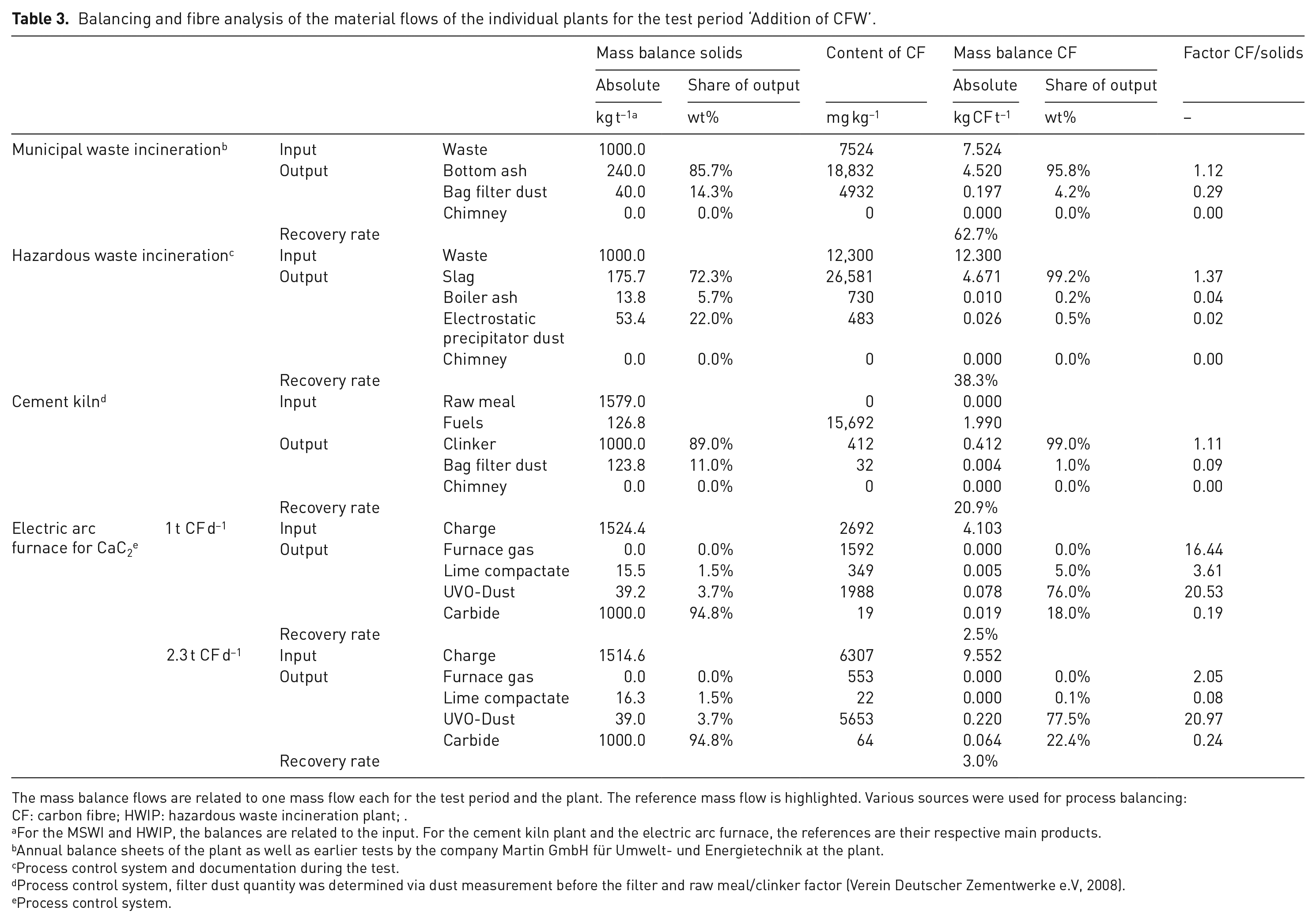
The mass balance flows are related to one mass flow each for the test period and the plant. The reference mass flow is highlighted. Various sources were used for process balancing:
CF: carbon fibre; HWIP: hazardous waste incineration plant; .
For the MSWI and HWIP, the balances are related to the input. For the cement kiln plant and the electric arc furnace, the references are their respective main products.
Annual balance sheets of the plant as well as earlier tests by the company Martin GmbH für Umwelt- und Energietechnik at the plant.
Process control system and documentation during the test.
Process control system, filter dust quantity was determined via dust measurement before the filter and raw meal/clinker factor (Verein Deutscher Zementwerke e.V, 2008).
Process control system.
The results of the large-scale test campaigns show that the two standard thermal waste treatment concepts using grate and rotary kiln firing are not suitable for the complete oxidation of CFs due to insufficient processing conditions (temperature and residence time). The recovery rates were 62.7 wt% (MSWI) and 38.3 wt% (HWIP). In both the processes, the majority of the unoxidised CFs are discharged via the bottom ash or slag, as evidenced by the high factor CF/solids (Table 3).
For the test in the cement kiln, only the results of the ‘addition of processed CF fluff’ via the burner pipe are shown in Table 3. The addition of a pre-preg role via the kiln feed showed an incomplete burnout in a preliminary investigation, so that this addition point was not followed up. For being used in a cement kiln, the waste must be prepared for the burner pipe. Due to the short test period, reliability of the results on the mass balance is limited. The recovery rate of 20.9 wt% is mainly based on the extrapolation of a few CFs found in the clinker, so that a final evaluation of this process path is not possible on the basis of the currently available data. This would require further investigations with longer test times and significantly higher application quantities.
In the electric arc furnace, in which CFW was used as a coke substitute, the CFs were applied in two different concentrations: 1.0 and 2.3 t CF day−1. The recovery rate was 2.5 and 3 wt%, respectively. Most of the recovered CFs were discharged from the electric arc furnace with the carbide furnace gas and subsequently separated in the hot gas filter. Most of these fibres showed no changes in their diameter, which implies that they were not exposed to thermal stress. The mass content of CFs in the dust (UVO-Dust) was 0.19 and 0.56 wt% CF for the respective dosing rates. This dust is currently marketed as a by-product for external usage. It must be, therefore, clarified whether such a product contaminated with CF could still be purchased, before a permanent use of CFW can take place in the plant.
Fibre discharge via the gas path
The PWMM was used during the investigations at the MSWI and HWIP. The PWMM is suitable for the qualitative detection of CFs in the high-temperature plant sections. Table 4 shows the results of the measurements for the two test periods ‘reference’ and ‘addition of CFW’. In the MSWI, CFs were detected in the exhaust gas in both periods. In the HWIP, fibres were only detected by means of PWMM during the addition of CFW. In both plants, the CF deposited on the particle wire mesh showed diameters in the range of 2 to 6 µm and lengths >100 µm, partly with traces of an oxidative attack on the fibre surface.
Results of the qualitative measurement using a Particle Wire Mesh Method in the high temperature range of the boiler.
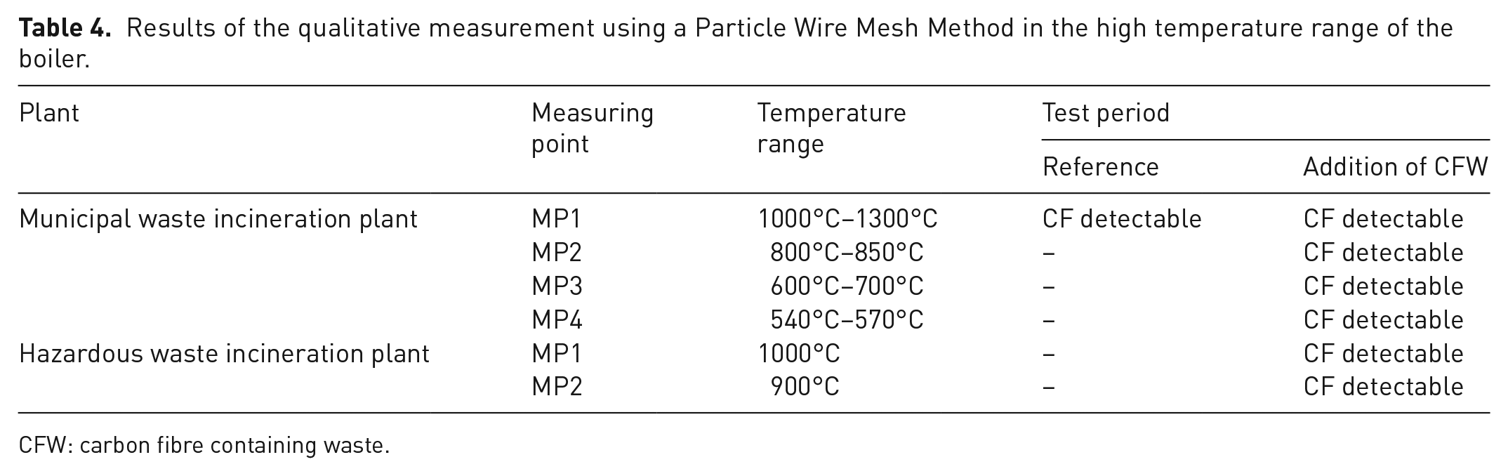
CFW: carbon fibre containing waste.
In the MSWI, the temperature range covered by PWMM was significantly larger than in the investigations at the HWIP. CF encrusted with salts during the cooling of the exhaust gas could be observed. A significant conversion of the CF could not be detected over the considered exhaust gas path or temperature range. Further information on the PWMM measurements is described in Supporting Information C.
The particulate matter measurements were carried out at various points in the exhaust gas path of the plants (Table 5). As stated before, no fibres were released into the environment by the chimney in all four plants considered.
Results of particulate matter measurements and fibre analysis of the separated dust.
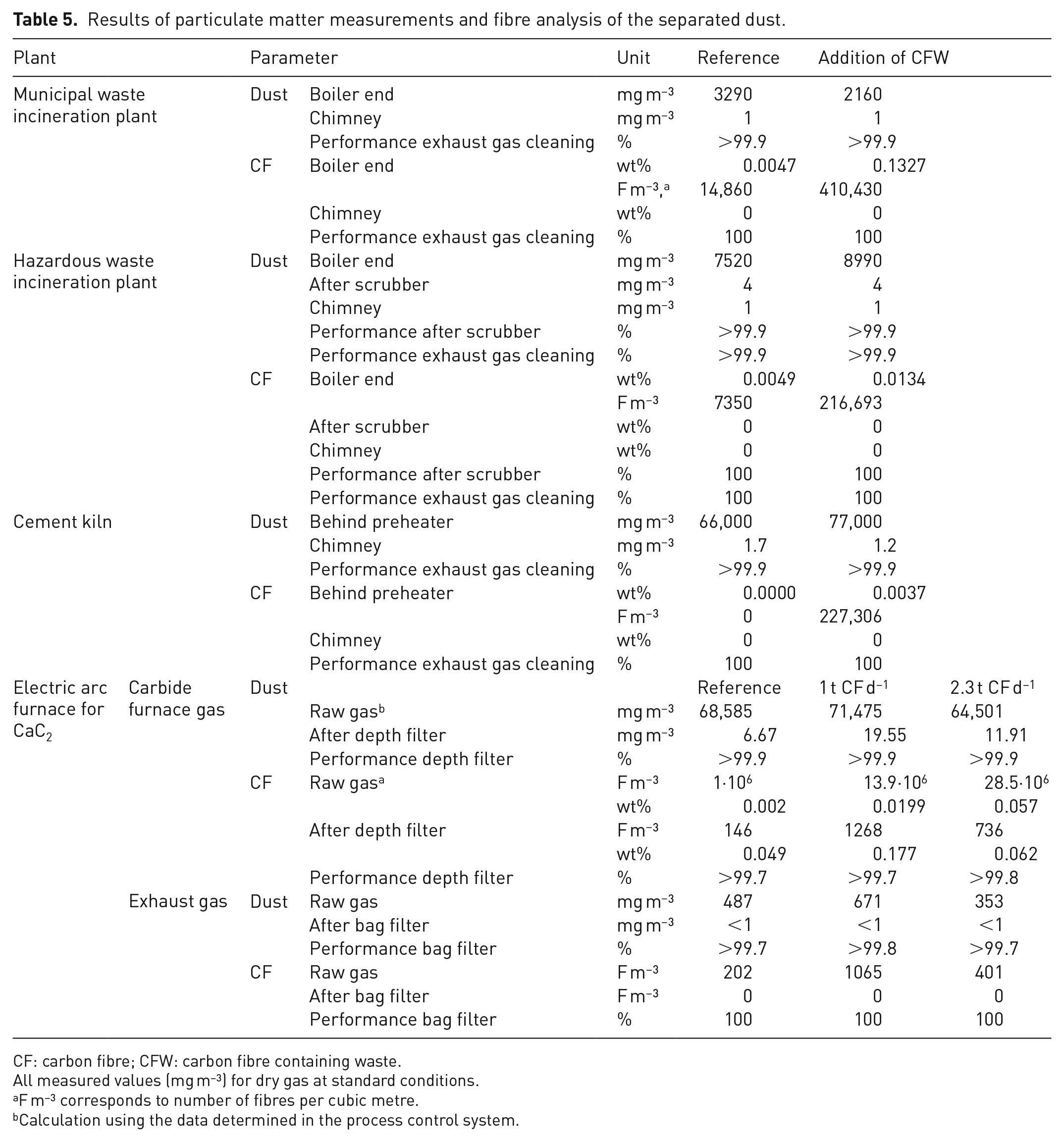
CF: carbon fibre; CFW: carbon fibre containing waste.
All measured values (mg m−³) for dry gas at standard conditions.
F m−³ corresponds to number of fibres per cubic metre.
Calculation using the data determined in the process control system.
In the HWIP, dust was removed after the boiler by an electrostatic precipitator. Its operation did not show any irregularities during the addition of CFW. Therefore, the tests cannot reproduce reports from MSWI on technical impairments due to CFs (Freimund, 2018). However, the discharge of CFs via the gas path in the HWIP was significantly lower than in MSWI, where primary air flows through the waste or fuel bed from below is, thus, possibly responsible for fibre discharge. In contrast to the measurements at the MSWI, the analysis of the length distribution of the CFs discharged from the rotary kiln showed only fibres shorter than 1 mm. However, previous investigations have shown that fibres with a length more than 1 mm, in particular, lead to defects in electrical and electronic components (Pride et al., 1980).
After de-dusting in the electrostatic precipitator, the exhaust gas from the hazardous waste incineration plant is passed through a scrubber. The analysis of the scrubber water revealed solid concentrations of <10 mg L−1. The CF contamination in the range of a few mg kg−1 was detected in the solids. Overall, this proportion is negligible within the mass balance. No CFs were found at the measuring point after the scrubber.
In the electric arc furnace, particulate matter measurements were carried out in two different gas streams. Both the resulting carbide furnace gas and the vapour exhaust air, which are extracted directly above the tapping, were sampled. The main discharge for unoxidised CFs is via the carbide furnace gas, which is de-dusted by a hot gas depth filter. For the two test periods with the addition of CFRP pellets, the dust concentrations after the hot gas filter are slightly above the reference state. The reason for this finding is assumed to be the slightly higher proportion of long-chain organic compounds in the carbide furnace gas due to the use of plastics (fibre matrix and additive in the pellets).
Generation of respirable fibres
In this paper, fibres are counted as respirable if they match the criteria according to the WHO, where diameter, D < 3 µm; length, L > 5 µm; and L/D ratio ⩾3:1.
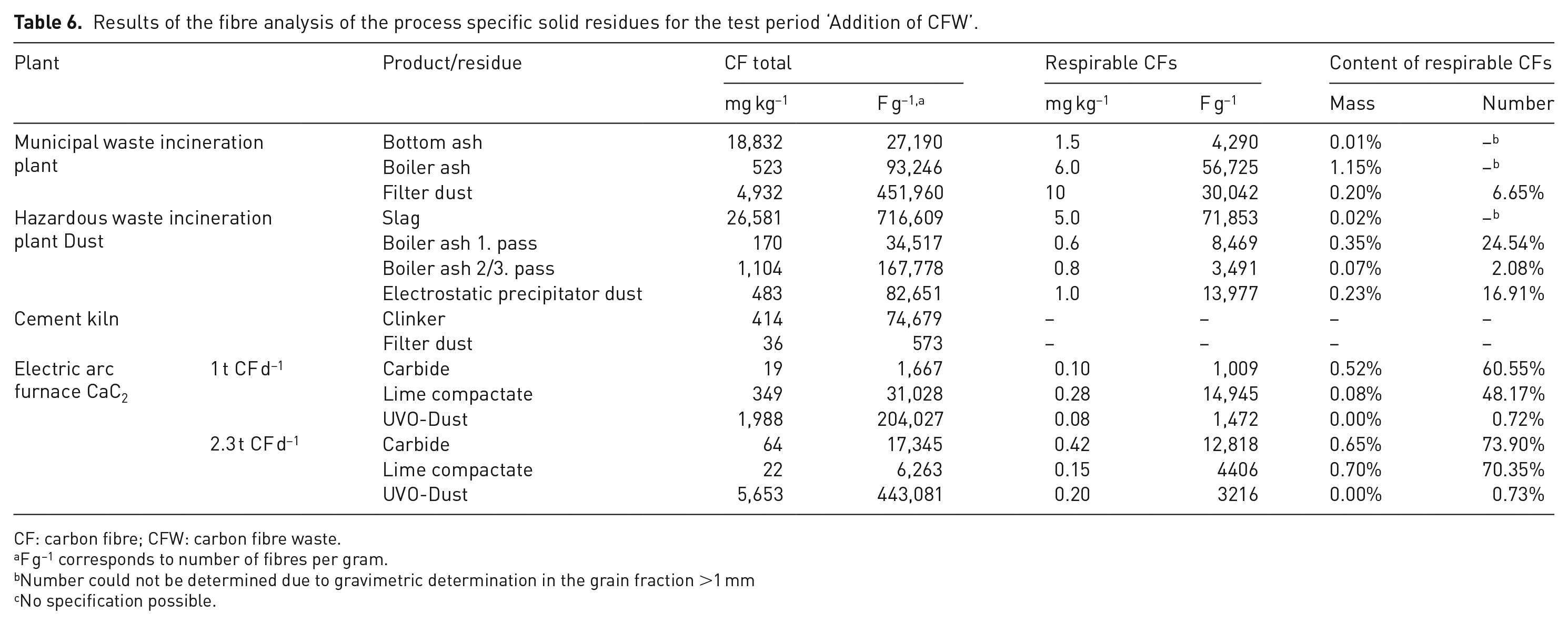
In order to assess the emergence of respirable CFs occurring from incomplete oxidation (Bell, 1980; Eibl, 2015a; Hertzberg, 2005), the process-specific products and residues were, therefore, examined in detail for respirable fibres. Table 6 shows the fibre mass and fibre number concentration for CFs in the products and residues of the investigated plants, as well as the proportion of respirable fibres in the recovered CFs for the test period ‘addition of CFW’.
Results of the fibre analysis of the process specific solid residues for the test period ‘Addition of CFW’.
CF: carbon fibre; CFW: carbon fibre waste.
F g−1 corresponds to number of fibres per gram.
Number could not be determined due to gravimetric determination in the grain fraction >1 mm
No specification possible.
This value was below 1.15 wt% in all investigations. In comparison, investigations of residues from mechanical processing of CFRP (e.g. milling) typically show values of <0.1 wt%. However, workplace situation (generation and release of respirable fibres) must also be considered for an assessment. (Mattenklott and Van Gelder, 2019).
The investigations at the MSWI revealed respirable fibre content below 10 mg kg−1 for all residues. In the bottom ash, the content was lower than in the boiler ash or filter dust. Accompanying workplace measurements (see Supporting Information E) showed that the currently recommended workplace limits according to TRGS 521 were safely met at MWI (Bundesministerium für Arbeit und Soziales, 2008; Fachbereich Holz und Metall der DGUV, 2014). The measurements in the HWIP also showed low content of respirable fibres in all residues.
Residues from the exhaust gases cleaning from thermal waste treatment plants (municipal and hazardous) are classified as hazardous waste; therefore, they are stored in closed containers and deposited underground. Further safety precautions in handling are therefore not necessary.
During the tests at the cement kiln, respirable CFs were occasionally detected. A reliable statement is not possible here, due to the limited examination conditions.
The use of CFRP pellets in the electric arc furnace did not lead to an increase in respirable fibres compared to the test period ‘Reference’. Most of the recovered CFs were discharged unchanged via the UVO-Dust. Only a few of the recovered CFs showed an oxidative attack and the characteristics of respirable fibres. During the increased addition of CFRP pellets (2.3 t day−1), the amount of recovered fibres increased accordingly. Respirable CF was also found in calcium carbide and lime compactate.
Conclusion
The aim of this project was to investigate the thermal treatment of CFW on an industrial scale. Energy recovery in MSWI, HWIP and cement kiln, as well as feedstock recovery in the electric arc furnace for calcium carbide production were examined. Figure 2 summarises the results of the large-scale experiments.
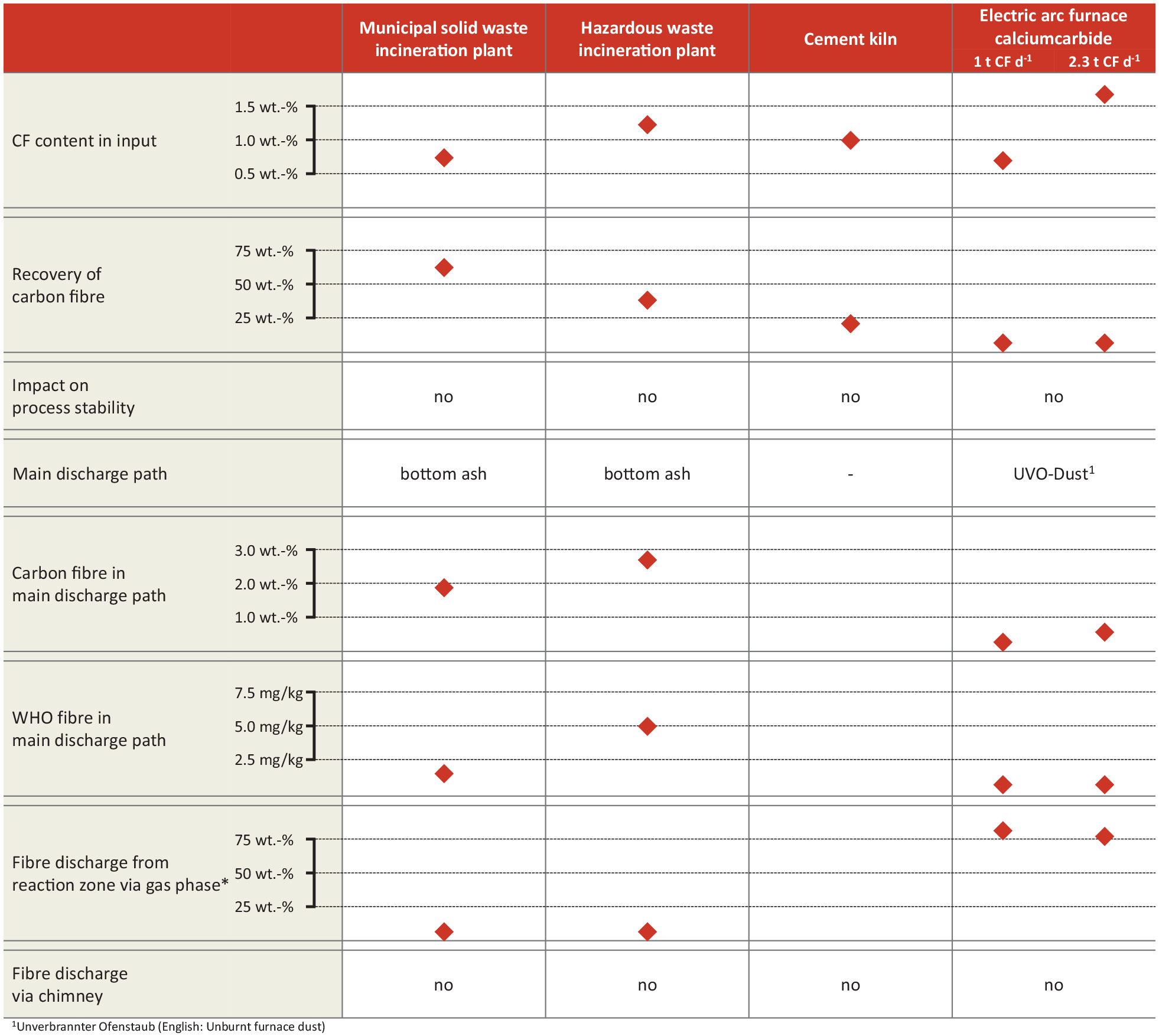
Summary of the results of the four large-scale experimental campaigns.
The results show that the two classical thermal waste treatment concepts with grate or rotary kiln firing are not suitable for a complete degradation of CF due to the insufficient processing conditions (temperature and residence time). Experience from the operation of MSWI can therefore be confirmed (Freimund, 2018). The CFs are discharged for the most part via the bottom ash or slag. Due to the incomplete conversion during thermal treatment, respirable CFs are formed in low concentrations.
A preliminary investigation in the cement kiln showed that a pre-treatment of the CFW as well as a suitable dosage is necessary to allow an appropriate thermal degradation. Against the background of the short test time and low input quantities of CFW, a final assessment of the suitability of this treatment path is not possible. This requires further long-term tests under co-incineration of CF-containing materials and a careful analysis of the process-specific product and residual materials.
The feedstock recycling of specially processed CFW, in this case CFRP pellets, in the production of calcium carbide led to low recovery rates and thus to high conversion rates of CFs. However, since CFs were detected in the UVO-Dust of the plant, the effects on the utilisation path of this by-product have to be clarified.
In summary, there is currently no industrial thermal process for the decomposition of non-recyclable CFs available. Nevertheless, products containing CFs should be collected separately in order to prevent uncontrolled input into thermal waste treatment plants.
Supplemental Material
sj-docx-1-wmr-10.1177_0734242X211038192 – Supplemental material for Thermal treatment of carbon-fibre-reinforced polymers (Part 2: Energy recovery and feedstock recycling)
Supplemental material, sj-docx-1-wmr-10.1177_0734242X211038192 for Thermal treatment of carbon-fibre-reinforced polymers (Part 2: Energy recovery and feedstock recycling) by Jan Stockschläder, Peter Quicker, Werner Baumann, Manuela Wexler, Dieter Stapf, Michael Beckmann, Christopher Thiel and Helmut Hoppe in Waste Management & Research
Footnotes
Acknowledgements
The authors would like to thank all operators, institutions and many friendly people who contributed to the success of this study. Our special thanks go to the companies AlzChem Trostberg GmbH, CFK Valley Stade Recycling GmbH & Co. KG, HeidelbergCement AG, HIM GmbH, Indaver Deutschland GmbH, Martin GmbH für Umwelt- und Energietechnik and Zweckverband für Abfallwirtschaft in Nordwest-Oberfranken.
Declaration of conflicting interests
The authors declared no potential conflicts of interest with respect to the research, authorship, and/or publication of this article.
Funding
The authors disclosed receipt of the following financial support for the research, authorship, and/or publication of this article: The study presented here was funded within the framework of a UFOPLAN project funded by the Federal Environment Agency Germany ‘Possibilities and limits of the disposal of carbon-fibre-reinforced plastic waste in thermal processes’ (FKZ 3716 34 3180). We would also like to thank the North-Rhine-Westphalian Ministry of Culture and Science for its funding within the framework ‘Forschungskolleg Verbund.NRW’ (Grant No.321-8.03.07-127599).
Supplemental material
Supplemental material for this article is available online.
References
Supplementary Material
Please find the following supplemental material available below.
For Open Access articles published under a Creative Commons License, all supplemental material carries the same license as the article it is associated with.
For non-Open Access articles published, all supplemental material carries a non-exclusive license, and permission requests for re-use of supplemental material or any part of supplemental material shall be sent directly to the copyright owner as specified in the copyright notice associated with the article.