
Abstract
This work presents a structured screening of seven alternative carbon fiber reinforced polymer (CFRP) systems for use in Type IV hydrogen pressure vessels. The objective was to reduce carbon fiber usage while maintaining mechanical integrity and industrial viability. The investigated configurations included matrix-modified epoxies, chemically functionalized fibers, and a high-strength fiber variant. All laminates were manufactured using wet filament winding and assessed through standardized mechanical and thermal testing.
To capture industrial relevance beyond material performance, a criteria-based evaluation framework was applied, incorporating processability, cost, scalability, sustainability, and regulatory compatibility. The results show that most variants achieved structural performance comparable to the reference system. A combined nanofiller–silane matrix delivered the highest strength values but exhibited reduced process stability, while a silane-modified matrix provided a more balanced performance profile with favorable practical scores. A radar-based comparison across five evaluation axes highlights trade-offs between mechanical performance and implementation feasibility.
The study demonstrates that multi-dimensional screening approaches are essential for identifying viable composite systems at an early development stage. The proposed evaluation framework is transferable in its methodological structure and decision logic, while absolute numerical scores remain application- and dataset-dependent.
Keywords
Introduction
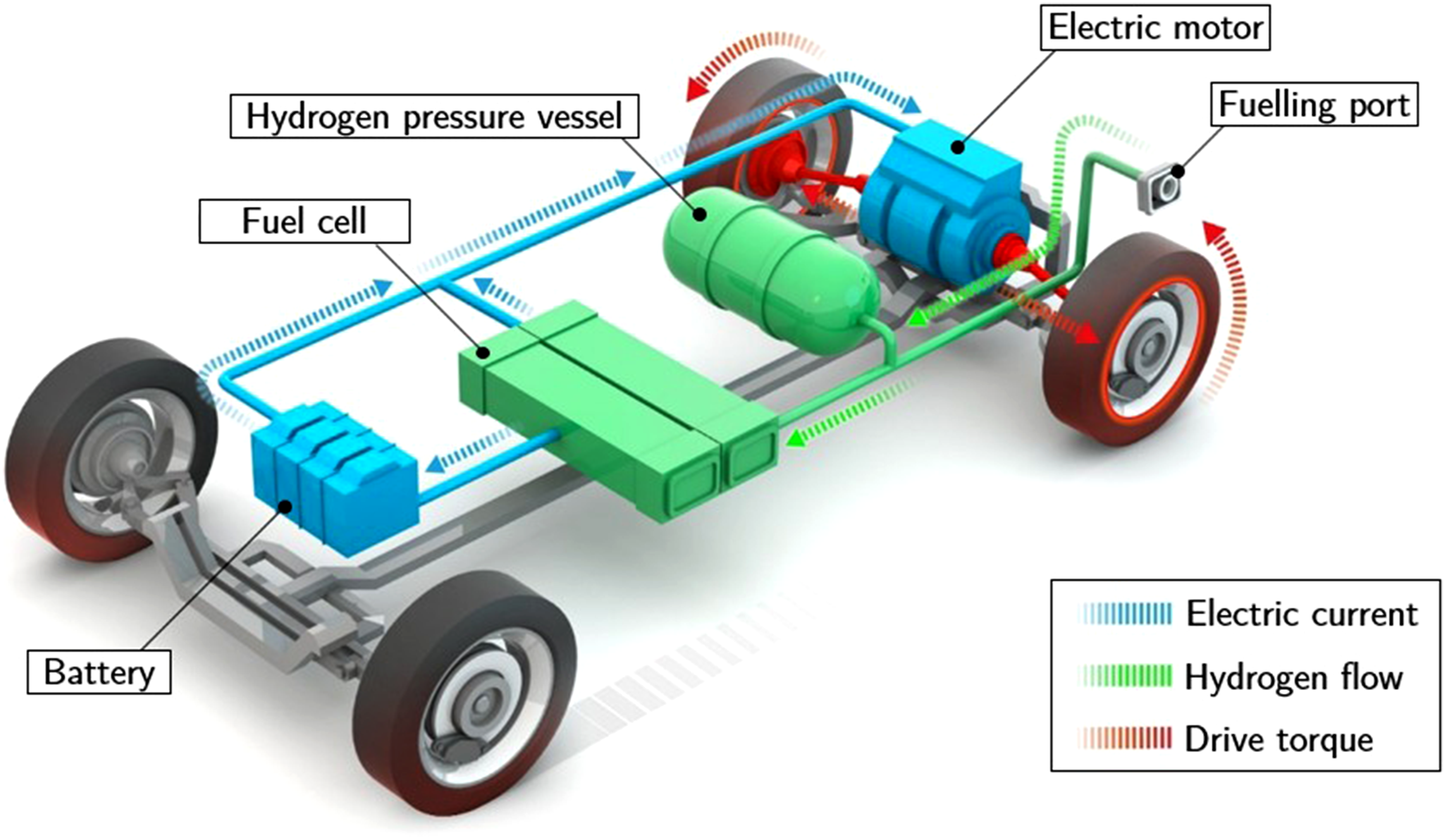
With the global energy transition moving toward climate neutrality, the demand for safe, efficient, and lightweight hydrogen storage systems is rising, particularly in mobility applications such as fuel cell electric vehicles (FCEVs), shown as schematic layout in Figure 1 including the integration of the hydrogen pressure vessel. Schematic layout of a fuel cell electric vehicle (FCEV), showing the integration of the hydrogen pressure vessel (Type IV) in the drivetrain architecture. Adapted from BMW Group
6
.
Among current pressure vessel technologies, Type IV composite designs are widely considered the most promising option due to their high gravimetric efficiency and ability to safely operate at pressures up to 700 bar, while minimizing structural weight.1–3
These vessels consist of a polymer liner fully wrapped in carbon fiber reinforced plastic (CFRP), offering a favorable balance between weight, strength, and chemical resistance. However, this performance comes at significant material cost: storing 1 kg of hydrogen may require up to 10 kg of carbon fiber, and the CFRP layer alone can account for nearly 50% of the total vessel cost.4,5 This high fiber demand presents a major economic and environmental barrier to broader adoption.
Optimizing the CFRP structure is therefore a central objective in ongoing research. If mechanical requirements are met, a thinner laminate can increase usable internal volume without changing the vessel’s outer dimensions, ultimately improving vehicle range and system efficiency. Achieving this requires maintaining or ideally enhancing the mechanical properties of the composite. Relevant targets include tensile strength and stiffness in axial and hoop directions, as well as matrix-dominated properties such as fracture toughness and interlaminar shear strength. These characteristics determine the vessel’s ability to withstand internal pressure, prevent delamination, and absorb localized stress concentrations. Layup configuration also plays a role, as hoop layers primarily carry pressure loads while domes require balanced in-plane behavior and damage tolerance.7,8
While adjustments to the fiber layup could offer further performance gains, they are not the focus of this study. Instead, a consistent layup strategy is maintained to isolate the influence of material variations within an industrially relevant wet filament winding process.
Numerous studies have explored targeted material innovations aimed at improving composite performance. These include nanofillers for matrix toughening, modified resins with enhanced fracture behavior, and fiber surface treatments to improve interface strength.9,10 Other work has examined alternative vessel concepts such as linerless Type V designs or cryogenic hydrogen storage.11,12,14 While several recent reviews have adopted a more holistic view that includes material properties, manufacturing strategies, sustainability, and regulatory aspects,13,14 most experimental studies still focus on isolated performance metrics under laboratory conditions. Rarely do they assess industrial scalability or regulatory integration.
This study addresses that gap by conducting a structured screening of seven alternative CFRP configurations for Type IV hydrogen pressure vessels. All variants are compatible with wet filament winding, the dominant industrial manufacturing route. To ensure application relevance, the assessment combines test-based and criteria-based evaluation: standardized mechanical and thermal tests are complemented by criteria-based ratings of processability, scalability, cost, sustainability, and regulatory compatibility. By keeping the layup fixed, the influence of material selection can be evaluated independently of geometry or process changes. The objective is to identify material systems that maintain or improve key mechanical properties, such as tensile strength, fracture toughness, and flexural performance, while also scoring favorably in terms of industrial applicability.
Materials and methods
Reference material system
To ensure both comparability and industrial relevance, this study selected a commercially established material system as the reference configuration. The chosen baseline reflects a widely used standard in pressure vessel manufacturing and fulfills practical requirements regarding performance, availability, and processability.
Based on its proven use in certified Type IV hydrogen pressure vessels and consistent reporting in the literature, the combination of Torayca® T700SC-24K-50C carbon fiber and a two-component epoxy matrix from Huntsman International LLC was chosen. The carbon fiber features a 1 wt% epoxy-compatible sizing (denoted as 50C), which promotes resin wetting and interfacial adhesion.15–17 The matrix system consists of ARALDITE® LY 1135-1A, ARADUR® 917-1, and Accelerator 960-1. This configuration is recognized for its balanced mechanical properties, favorable impregnation behavior, and full compatibility with wet filament winding processes.5,16,17 All experimental results from alternative material variants were benchmarked against this reference.
Investigated material variants
This study aims to identify material systems that reduce overall carbon fiber demand in pressure vessel structures while maintaining or improving mechanical performance and industrial applicability. This includes tensile and flexural strength, interfacial performance, and fracture toughness, as well as processing characteristics relevant for wet filament winding.
To address this objective, a set of alternative fiber–matrix configurations was selected based on a combination of literature insights and pre-screening criteria such as feasibility, material availability, and expected performance impact. The focus was placed on practical and scalable concepts that are compatible with established wet filament winding processes and representative of near-term industrial relevance.
Based on this rationale, the selected variants were grouped into three conceptually distinct categories: resin modifications, fiber surface treatments, and alternative fiber systems. For objective comparison, all resin variants were paired with the same fiber type, Torayca® T700SC-24K-50C, and a consistent hardener system comprising ARADUR® 917-1 and Accelerator 960-1. This ensured comparable curing conditions and eliminated confounding effects related to resin–fiber interactions.
R1 (silane-modified matrix)
This variant, designated R1, uses the reference epoxy system modified with Dynasylan® GLYEO, a glycidyl-functional organosilane added directly to the matrix. The silane concentration was set to 2.5 parts per 100 parts epoxy resin, corresponding to approximately 1.3 wt% relative to total matrix mass. Silane coupling agents such as GLYEO are typically used to improve chemical bonding between the resin and the fiber surface by forming covalent or hydrogen bonds with both phases. In matrix-integrated form, they are reported to enhance interfacial adhesion, reduce interfacial debonding under load, and improve long-term moisture resistance. These effects are particularly relevant for pressure vessel applications, where robust fiber–matrix interaction contributes to delamination resistance and overall durability under cyclic and high-pressure conditions. Although most studies apply silanes to the fiber surface, the manufacturer reports compatibility with bulk epoxy formulations. The selected dosage falls within the typical range for matrix-integrated coupling agents. 18
R2 (nanofiller matrix (ALBIDUR® F061))
This variant, labeled R2, uses an epoxy system modified with nanoscale silica and polysiloxane-based core-shell particles (ALBIDUR® F061). These modifiers are designed to enhance fracture toughness through energy dissipation mechanisms at the filler–matrix interface, particularly via rubbery domains embedded in the thermoset network.
In the context of pressure vessels, fracture toughness is a critical matrix-dominated property that contributes to damage tolerance under localized stress peaks, crack propagation resistance, and overall laminate integrity, especially in regions subject to transverse loads or manufacturing-induced defects. Improved matrix toughness can delay the onset of delamination and reduce the sensitivity to microcracks caused by handling, impact, or cyclic pressurization.
The resin formulation was used as delivered, without further dilution or modification. Its actual effect on laminate-scale properties depends strongly on filler dispersion, particle–matrix compatibility, and local resin content.19,20
R3 (combined nanofiller + silane)
This variant combines the fracture-toughened epoxy system used in R2 (ALBIDUR® F061) with the silane coupling agent Dynasylan® GLYEO employed in R1. The goal is to evaluate whether a simultaneous improvement of matrix toughness and interfacial adhesion can provide synergistic benefits in composite performance.
In Type IV hydrogen pressure vessels, mechanical failure is typically governed by a combination of fiber-dominated and matrix-dominated mechanisms. Matrix cracking, fiber–matrix debonding, and interlaminar delamination can be initiated by local stress concentrations, handling defects, or cyclic pressurization. A tougher matrix can improve damage tolerance by dissipating energy at crack tips, while a stronger interface can reduce debonding and delay the onset of interfacial failure.
The combination of these two modification strategies aims to enhance both in-plane fracture resistance and through-thickness integrity. While the two components have been individually validated in prior work, their combined use in structural epoxy systems remains largely unexplored and may pose additional challenges in terms of dispersion, viscosity, and curing behavior. 18
Both surface-functionalized variants, F1 and F2, use desized Torayca® T700SC-12K-50C carbon fibers that were chemically modified via diazonium-based electrochemical grafting on a lab-scale setup.
F1 (aromatic amine-functionalized fibers)
In this variant, aromatic amine groups were introduced to the fiber surface to enable covalent bonding with the epoxy matrix. The goal is to increase interfacial strength and reduce debonding under pressure and shear loading, thereby enhancing laminate integrity in vessel structures. Potential side effects include increased brittleness and resin uptake during handling and winding. 21
F2 (phenol-functionalized fibers)
Here, phenolic OH groups were grafted to increase surface polarity and promote hydrogen bonding with the resin. Improved wettability is expected to support better matrix infiltration and reduce weak interphases, which may improve local damage resistance. However, the lack of direct chemical reactivity with the epoxy network may limit the effect to surface energy enhancement. 21
A1 (alternative fiber system)
This variant employs Torayca® T720SC-36K-50C, a high-strength, standard-modulus carbon fiber that is reported to offer approximately 20% higher tensile strength compared to the T700 reference grade. 16 The aim is to evaluate whether this enhanced fiber-level property translates into improved composite tensile performance under wet filament winding conditions. In the context of pressure vessels, higher fiber strength could enable equivalent structural capacity at reduced fiber volume, thereby supporting the broader goal of material-efficient laminate designs.
Higher-strength commercial fibers such as Torayca® T800 or T1000 were considered but were not included, as these grades are generally not used for wet-filament-wound Type IV pressure vessels due to their substantially higher cost, limited availability in large-tow formats, and property profiles not optimized for the strain compatibility and processing robustness required in pressure vessel structures. In contrast, Torayca® T720SC-36K-50C represents the highest-strength fiber that is commercially viable and used or considered within industrial pressure vessel manufacturing. For this reason, T720 was selected as the sole high-strength benchmark in this study.
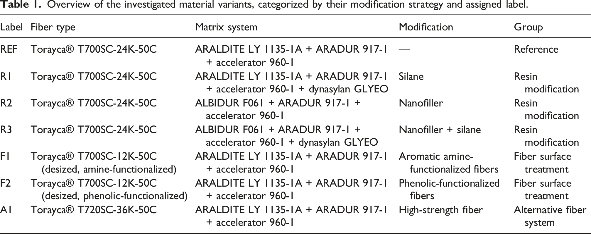
Overview of the investigated material variants, categorized by their modification strategy and assigned label.
Manufacturing process
Wet filament winding is widely used to produce Type IV hydrogen pressure vessels, offering high material efficiency, excellent fiber alignment, and scalability for composite manufacturing. 2 In this study, flat composite plates were produced using an adapted version of this process to enable standardized material screening.
Following ISO 1268-5 guidelines for plate winding, fiber rovings were impregnated in-line via a resin bath and wound in alternating ±90° orientations onto a flat aluminum base mold as shown in Figure 2. Wet filament winding setup for producing flat CFRP laminates.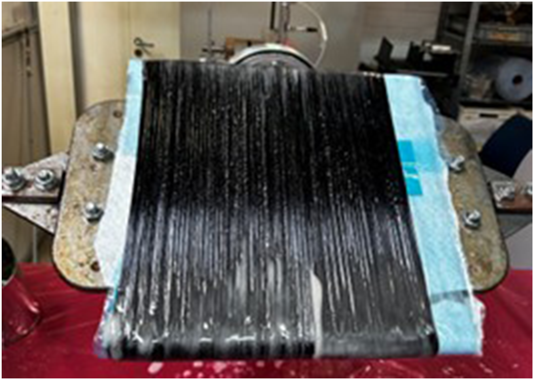
The layup was then vacuum-bagged and cured in a heated press at 140°C and 30 bar for 4 h, in accordance with supplier specifications. The resulting plates were demolded and trimmed for mechanical and thermal testing. Plate thickness, fiber content, and void fraction were monitored to ensure comparability between variants.17,22
While flat laminate geometry differs from that of full-scale vessels, it allows for standardized testing of tensile, flexural, and interlaminar properties. This approach is widely used in composite material screening and provides a reproducible basis for early-stage evaluation of fiber–matrix configurations under process-relevant conditions. While absolute values may differ due to geometric effects, flat specimens offer essential mechanical data that support material selection and design development for curved structures such as hydrogen pressure vessels.23,24
For each material variant, multiple plates were produced until the laminate reached the thickness range required for the planned tests and exhibited acceptable processing quality. The number of layers was adjusted accordingly, which is standard practice for unidirectional laminates, as comparability is governed primarily by fiber orientation, curing conditions, and fiber volume fraction. All plates were manufactured from the same resin and fiber batches to avoid material batch-to-batch variability.
No material-specific process optimization was performed for the individual variants. All laminates were manufactured using identical processing parameters to ensure direct comparability between material concepts. The objective of this study was to evaluate the behavior of alternative material systems under a conventional wet filament winding process, rather than to investigate tailored process adaptations for each material variant.
Mechanical testing methods
The mechanical behavior of the produced composite plates was assessed through standardized tensile, flexural, and interlaminar shear testing. All tests were performed in accordance with international ISO standards, ensuring both comparability and methodological consistency. These standards were selected because the available testing equipment, fixtures, and optical extensometry systems in our laboratory are specifically configured for the corresponding ISO procedures, which are widely established for unidirectional CFRP laminates. Mechanical testing was performed on specimens extracted from the plate that met both the target thickness and the processing quality criteria for each variant. Between five and eight valid specimens were tested for tensile strength, five to six for four-point bending, and seven for the double-beam shear test. All specimens were taken from laminates manufactured using identical resin and fiber batches to avoid material batch-to-batch variability. All specimens were tested in the dry, as-fabricated state after curing and demolding, without additional conditioning.
Tensile testing (ISO 527-5)
Unidirectional tensile properties were measured according to ISO 527-5 using Type A specimens with bonded tabs. The specimens were cut parallel to the fiber direction from flat plates and tested at a crosshead speed of 2 mm/min. Strain was measured over a 50 mm gauge length using a video-based optical extensometer system. Tensile strength, modulus, and strain at failure were calculated following the procedures defined in the standard. 25
Four-point bending (ISO 14125)
Flexural properties were determined according to ISO 14125 using the four-point bending method. This configuration enables the characterization of flexural strength and stiffness under matrix-dominated transverse loading. The test setup consisted of two outer supports and two inner loading points, with force applied at a constant rate until the specimen failed or a significant load drop occurred. Class III specimens were used, with dimensions adapted to the plate thickness according to the standard’s specified span-to-thickness ratio. 26
Double-beam shear test—(“five-point bending”) (ISO 19927)
Interlaminar shear strength was assessed using the double-beam shear test in accordance with ISO 19927. This five-point bending configuration minimizes bending effects, enabling a more accurate determination of pure shear strength in unidirectional laminates. The setup included three support rollers and two loading rollers, arranged symmetrically. Specimen dimensions, roller diameters, and loading speed followed the standard specifications. Tests were stopped upon specimen fracture or when the applied force dropped by 80%. 27
Thermal and physical characterization
Thermal and physical testing was conducted to verify matrix curing and to assess the influence of resin and interface modifications on thermal stability. These factors are critical for pressure vessel reliability, where complete curing and thermal stability are essential for safe operation.
Specimens for DSC and TGA were taken from the same plates used for mechanical testing to ensure that all analyses reflected identical curing conditions and material states. Three DSC specimens and one representative TGA specimen were analyzed per variant, in accordance with the applicable ISO standards.
DSC (ISO 11357-2)
Differential Scanning Calorimetry (DSC) was used to assess the glass transition temperature (Tg) of each matrix system in accordance with ISO 11357-2. Each sample was subjected to a two-step heating cycle, and Tg was determined from the first heating segment. The cycle parameters were selected based on standard practice for epoxy thermosets and adapted to the materials under study. This test helps identify differences in curing state and matrix composition between the variants. 28
TGA (based on ISO 1172 and ISO 11358-1)
Thermogravimetric analysis (TGA) was conducted to quantify fiber content and thermal stability. Approximately 1 g of sample was subjected to a stepwise heating program adapted from standard methods and tested under protective atmosphere. From the recorded mass loss, the resin content and inorganic residue were calculated. This method helps verify laminate quality and enables comparison of fiber volume fractions between configurations.29,30
Criteria-based evaluation
During early-stage material screening, only a limited number of candidates proceed to full-scale development. To support this selection process, this study combines mechanical and thermal testing with criteria-based screening for industrial feasibility. While test-based performance evaluation is essential, the successful application of materials in high-pressure hydrogen vessels also depends on practical considerations, including processability, cost-efficiency, material availability, and compliance with regulatory requirements.
Processability and process changes
This criterion evaluates how easily a material system can be integrated into established wet filament winding processes. It considers effects on resin handling, fiber wet-out, curing cycles, and demolding behavior. Material variants that require significant changes to process parameters or equipment are considered less favorable.
Technological readiness
This criterion reflects the maturity level of a material system. It captures whether the concept has progressed beyond basic laboratory trials toward validation under conditions relevant for industrial application. Materials that have already been processed on pilot-scale equipment or in production-relevant environments are rated higher than those limited to small-scale or experimental setups.
Scalability
Scalability addresses the feasibility of applying the material system in large-scale composite pressure vessel production. Considerations include compatibility with automated winding and curing equipment, repeatability across batch sizes, and process robustness under production conditions.
Cost and availability
This criterion reflects the economic and logistical accessibility of the materials. It includes raw material prices (e.g., fiber and resin costs), supplier diversity, and potential sourcing risks. Systems relying on niche chemicals or limited suppliers are evaluated less favorably.
Sustainability
Sustainability encompasses environmental aspects such as carbon footprint, fossil content, and recyclability. While a full life cycle analysis is beyond the scope of this study, rankings are informed by available data on raw material origin, manufacturing impact, and end-of-life options.
Regulatory compatibility
Compliance with existing hydrogen pressure vessel regulations (e.g., GTR No. 13, ECE R134) is critical for industrial implementation. This criterion reflects how likely a material system is to meet certification standards without requiring extensive new testing or validation procedures.
Summary of criteria and scoring framework
While the six defined criteria refer to qualitative industrial feasibility aspects, this summary also introduces how test-based mechanical results are conceptually integrated into the overall evaluation framework. All six criteria are evaluated using a uniform 0 to 5 scoring scale to support comparability across material variants and performance domains. This approach is commonly applied in multi-criteria decision-making (MCDM), early-stage materials screening, and engineering design frameworks. 31
Scores are assigned based on a combination of supplier information, relevant literature data, and expert judgment. Specific threshold definitions for each score are introduced the results section as part of the applied evaluation to ensure consistency and contextual relevance.
The six evaluation axes serve different methodological purposes and are therefore not based on identical scoring logics. The industrial feasibility criteria (Axes 2–5) are defined using fixed, criteria-defined reference scales representing external boundary condition such as availability, process compatibility, regulatory readiness, and cost constraints.
In contrast, Axis 1 (Mechanical Performance) is intentionally based on a relative normalization within the investigated dataset. Absolute mechanical threshold values cannot be universally defined for composite pressure vessels, as required strength and stiffness levels strongly depend on application-specific factors such as pressure class (e.g., 300 bar vs 700 bar), vessel geometry, safety factors, and system-level design choices. Consequently, mechanical performance is evaluated comparatively to identify relative improvements or trade-offs within a defined design space rather than against absolute engineering limits.
Results
Mechanical and interface properties
As outlined in the mechanical testing methods section, a series of standardized mechanical tests was conducted to evaluate the structural performance of the investigated composite systems. The results presented in this section provide test-based data on the fiber-dominated, matrix-dominated, and interlaminar behavior of each configuration under the applied loading conditions.
To improve comparability, tensile and four-point bending test results were normalized to a reference fiber volume fraction (FVF) of 60% v/v, based on the average fiber content determined by TGA. The normalization to
All figures in this section follow a consistent format to enable direct comparison across material variants. The x-axes represent the seven tested configurations, using the variant labels defined before. The y-axes show the measured property for each test, employing SI units in accordance with the respective ISO standard. For each configuration, black diamonds indicate the individual specimen values, while the colored bars represent the arithmetic mean. Error bars correspond to one standard deviation above and below the mean.
Tensile testing (tensile strength)
The results of the unidirectional tensile tests are presented in Figure 3. Tensile strength of CFRP variants determined by uniaxial tensile testing at 0° fiber orientation according to ISO 527-5. Bars indicate mean ± standard deviation; diamonds represent individual specimen values. Results normalized to 60% v/v fiber content.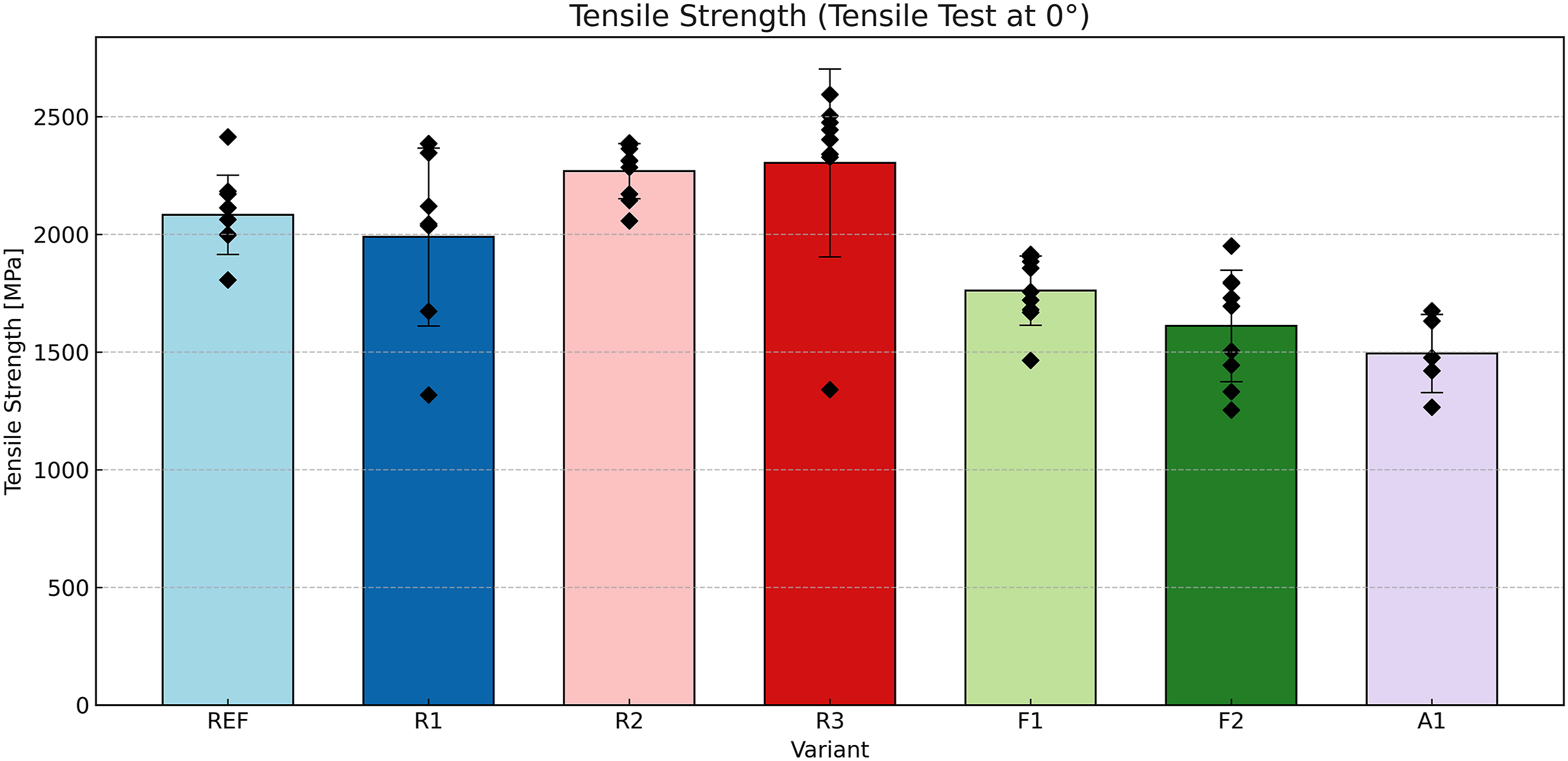
The reference configuration (REF) achieved a mean tensile strength of approximately 2080 MPa, with a narrow standard deviation. This confirms its status as a robust industrial baseline for fiber-dominated load conditions.
The highest tensile strength was observed in R3 (approximately 2300 MPa), followed closely by R2 (approximately 2250 MPa). Both variants use the same nanofiller-modified epoxy matrix system (ALBIDUR® F061), which contains nanoscale silica and rubbery core-shell domains to enhance fracture toughness. R3 includes an additional silane coupling agent (Dynasylan® GLYEO), intended to further strengthen the fiber–matrix interface. Given the small difference and associated scatter, the observed improvement should be interpreted with caution and may reflect batch-specific processing effects rather than intrinsic material superiority.
Variant R1 (silane-modified matrix) reached around 1980 MPa, which is slightly below the REF value.
The chemically surface-modified fiber systems F1 and F2 showed reduced tensile strength of approximately 1750 MPa and 1620 MPa, respectively. In both cases, the original sizing was fully removed through thermal desizing prior to the electrochemical surface treatment. This removal eliminates the protective layer that typically enhances fiber handling and matrix adhesion. The absence of sizing can lead to fiber surface damage, micro-defects, and reduced strength retention.
The alternative fiber variant A1, despite using a high strength 36K filament (T720), underperformed with a mean tensile strength of only 1500 MPa.
Four-point bending (maximum bending strength and flexural modulus)
The results of the transverse four-point bending tests are summarized in Figures 4 and 5. These tests assess matrix-dominated behavior and laminate stiffness in the transverse (90°) direction, which is particularly relevant for understanding composite performance under hoop stress and local impact conditions. Figure 4 presents the maximum bending strength. Maximum bending strength of CFRP variants determined by four-point bending testing at 90° fiber orientation according to ISO 14125. Bars indicate mean ± standard deviation; diamonds represent individual specimen values. Results normalized to 60% v/v fiber content. Flexural modulus of CFRP variants determined by four-point bending testing at 90° fiber orientation according to ISO 14125. Bars indicate mean ± standard deviation; diamonds represent individual specimen values. Results normalized to 60% v/v fiber content.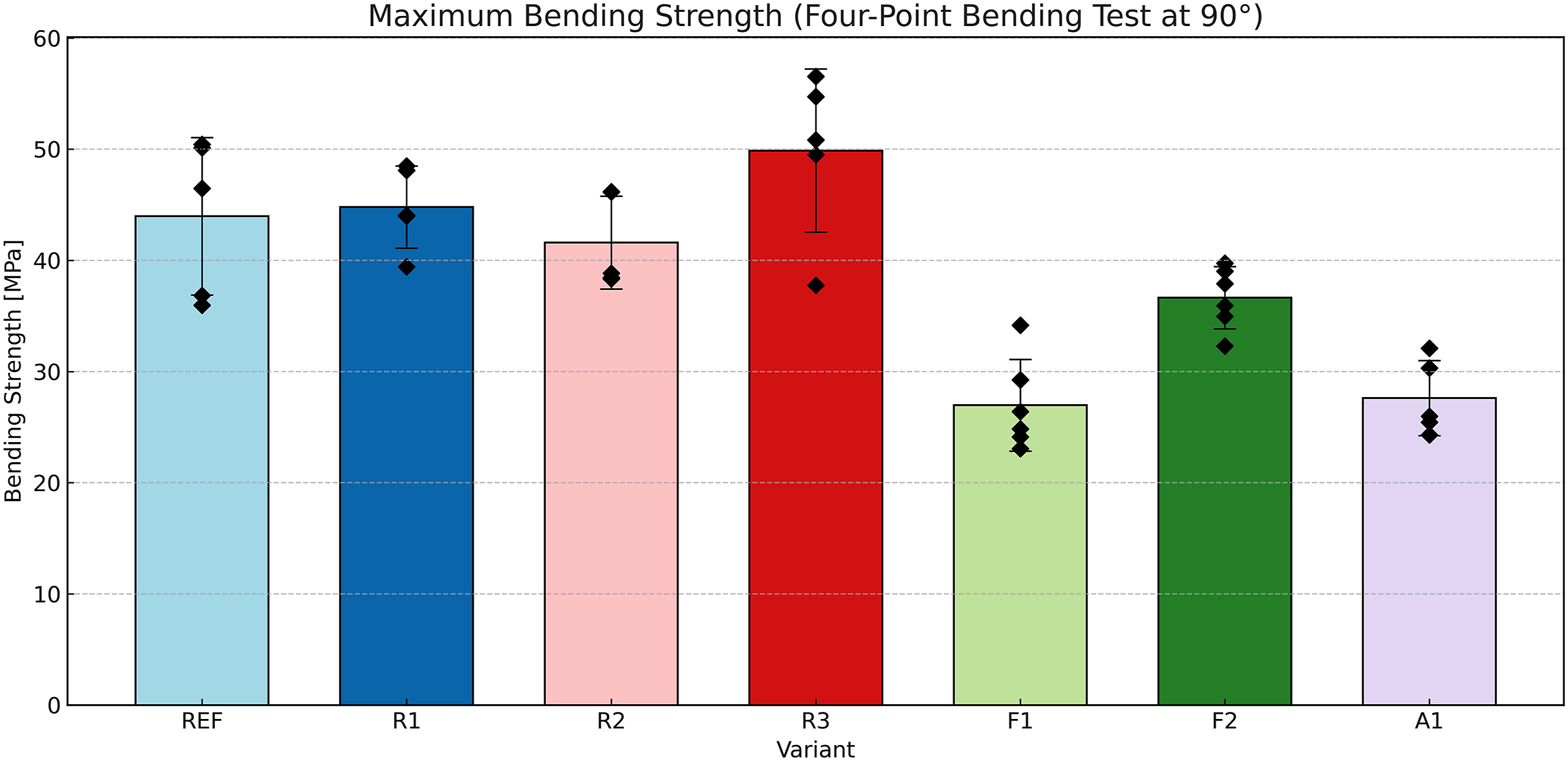
In terms of maximum bending strength (Figure 4), the R3 variant outperformed all other configurations with a mean value of approximately 50 MPa. This result confirms the potential of combining nanofillers and silane to enhance matrix-dominated failure resistance. However, the relatively wide scatter indicates some sensitivity to processing parameters, such as dispersion quality or local interface variation.
R1 and the reference system (REF) followed closely, achieving mean values of 45 MPa and 44 MPa, respectively. This confirms that the silane-modified matrix in R1 maintains reliable bending performance and may slightly improve transverse strength under ideal processing conditions.
R2 exhibited a moderate strength of 42 MPa, showing that matrix toughening alone does not lead to a bending strength benefit compared to the REF. The performance is stable but unremarkable, suggesting limited effect on transverse failure mechanisms.
The surface-modified fiber systems F1 and F2 underperformed, reaching only 28 MPa and 36 MPa, respectively. F2 performed slightly better, possibly due to more stable surface chemistry and reduced brittleness.
A1, despite the use of a high-strength fiber, also reached only 28 MPa. This highlights the importance of adequate impregnation in dense filament bundles, since incomplete matrix infiltration can greatly diminish matrix-dominated strength.
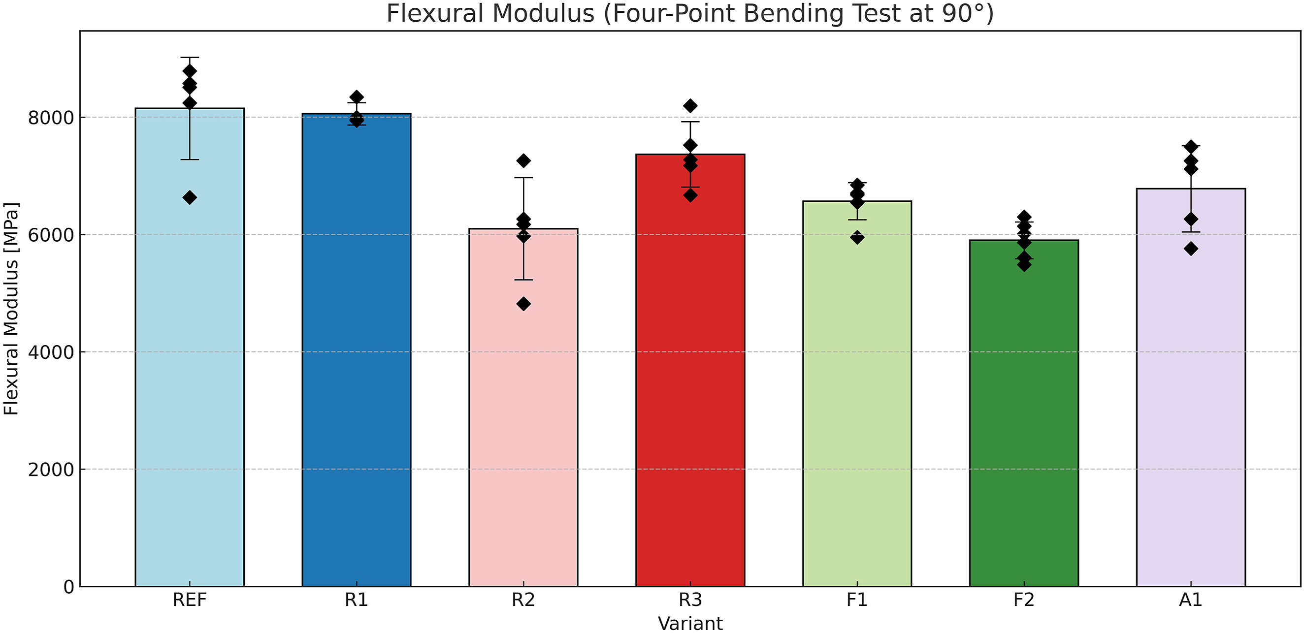
Unlike the bending strength results, the flexural modulus shown in Figure 5 reveals a different ranking among the material variants.
The reference system (REF) achieved the highest value, around 8200 MPa, indicating a well-balanced stiffness response under transverse elastic loading.
R1 followed closely with a mean of 8100 MPa, confirming that the silane additive has no adverse effect on matrix stiffness and may even stabilize the elastic modulus through improved stress transfer at the interface.
R3 showed a flexural modulus of approximately 7300 MPa, which is lower than REF and R1 but still within a functionally relevant range.
R2 had the lowest modulus among the matrix-modified variants, with 6100 MPa. This suggests that while the nanofillers in ALBIDUR® F061 improve toughness and strength, they reduce stiffness under elastic loading.
The fiber-modified systems F1 and F2 exhibited moduli of approximately 6600 MPa and 5900 MPa, respectively.
A1, using the denser 36K fiber tow, achieved a modulus of around 6800 MPa. However, the value remains below REF.
Double-beam shear test—Five-point bending
The interlaminar shear strength results, obtained via the five-point bending method according to ISO 19927, are presented in Figure 6. Interlaminar shear strength (ILSS) of CFRP variants determined by five-point bending testing (ISO 19927). Bars indicate mean ± standard deviation; diamonds represent individual specimen values. Results normalized to 60% v/v fiber content.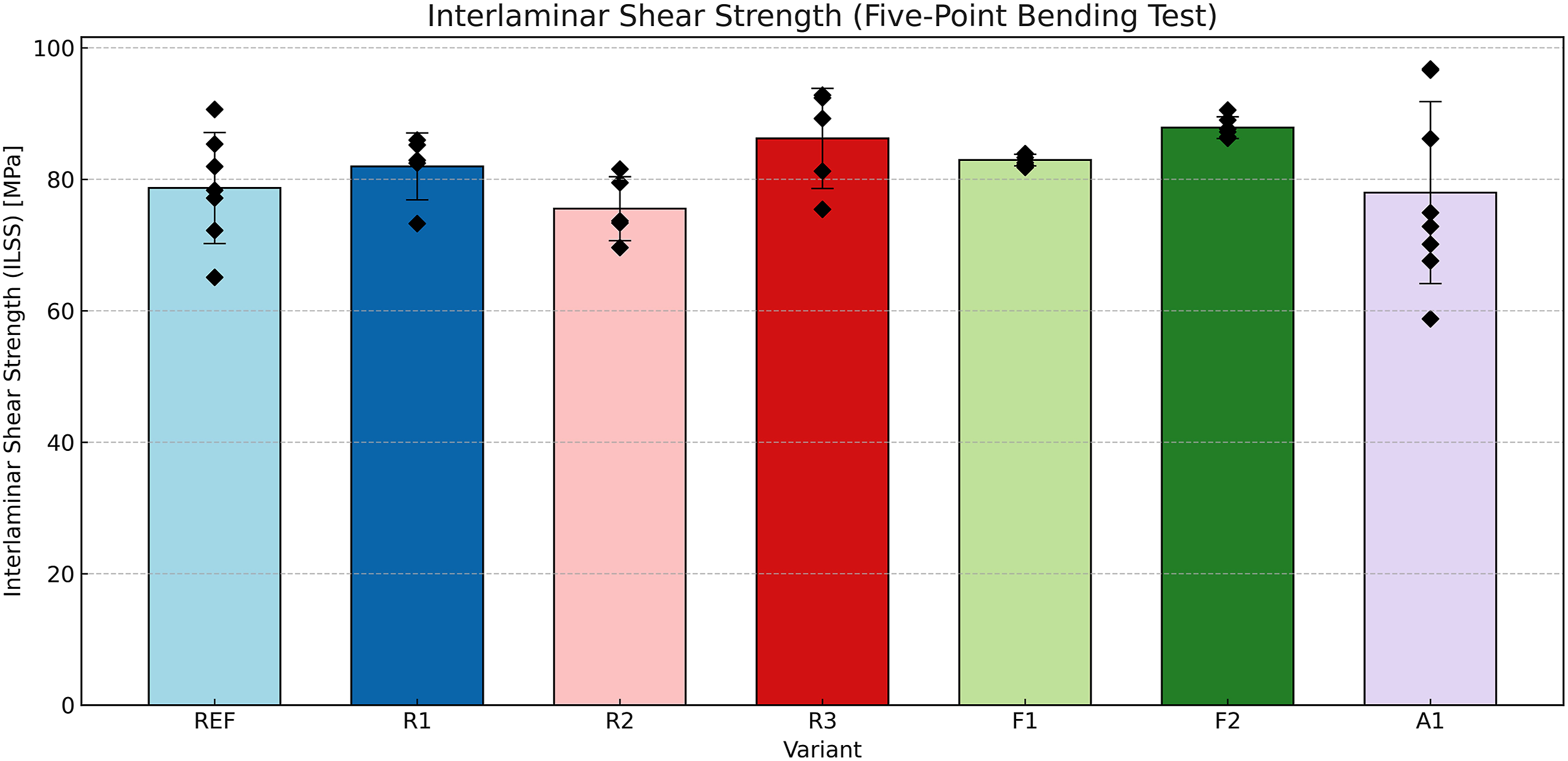
Among all variants, F2 and R3 exhibited the highest ILSS values, with mean strengths of approximately 88 MPa and 87 MPa, respectively. This suggests that both the phenol-functionalized fiber surface (F2) and the combined nanofiller–silane-modified matrix (R3) are effective in enhancing interfacial shear strength.
Variant F1 also performed well, reaching 83 MPa. Despite the desizing and chemical grafting process, the amine-modified fibers appear to support adequate interfacial shear strength.
R1 and R2 showed moderate performance with values of 82 MPa and 75 MPa, respectively.
The reference system (REF) and the alternative fiber variant A1 both achieved ILSS values around 78 MPa, confirming a consistent baseline performance. In the case of A1, the scatter is notably higher.
Notably, the ILSS values showed a relatively narrow range, spanning approximately 75 to 88 MPa. All systems demonstrated shear strength values within a technically acceptable range, suggesting general compatibility with filament-wound composite architectures for pressure vessel applications.
Thermal and physical properties
DSC
The results of the differential scanning calorimetry (DSC) measurements are presented in Figure 7, which summarizes the glass transition temperatures (Tg) of all tested material systems. Glass transition temperature (Tg) of CFRP variants determined by Differential Scanning Calorimetry (DSC) according to ISO 11357-2. Bars indicate mean ± standard deviation; diamonds represent individual specimen values.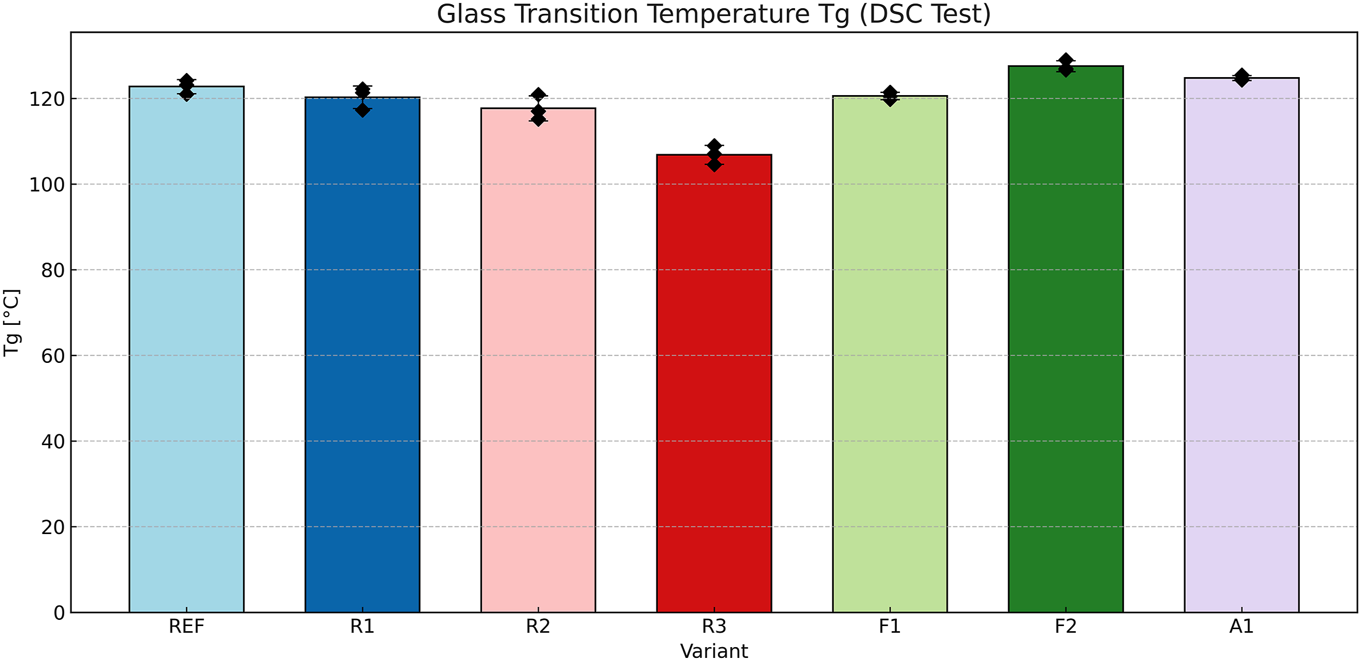
All variants exhibited Tg values in the range of approximately 105°C to 128°C, indicating that each matrix system reached a sufficient degree of cure under the applied thermal cycle. The reference system (REF) showed a Tg of around 123°C, serving as the benchmark.
Variants R1, R2, F1, F2, and A1 achieved similar Tg values between 120°C and 128°C, confirming that neither the matrix modifications nor the surface treatments significantly interfered with the curing behavior.
In contrast, R3 displayed a noticeably lower Tg, averaging just above 105°C, but still within the acceptable range for structural epoxy systems (typically 100°C to 130°C),. 32 In addition, Type IV hydrogen pressure vessel regulations such as ECE R134 and GTR No. 13 do not specify a fixed minimum glass transition temperature. Instead, thermal suitability is demonstrated through functional qualification tests, including pressure cycling at elevated temperatures (85°C). 33,34 All investigated matrix systems meet these requirements. Nevertheless, no indicators of undercuring, such as tacky surfaces, void formation, or mechanical degradation, were observed during processing or subsequent testing.
TGA
The results of the thermogravimetric analysis (TGA), conducted to estimate the volume composition of the composite laminates, are presented in Figure 8. The figure shows the relative volume fractions of fiber, matrix, and residual inorganic content after thermal degradation in an inert atmosphere. Each bar represents a single measurement per material variant and stacks the three constituents. Volume composition of CFRP variants determined by thermogravimetric analysis (TGA) based on ISO 1172 and ISO 11358-1. Bars indicate fiber, matrix, and residue volume fractions.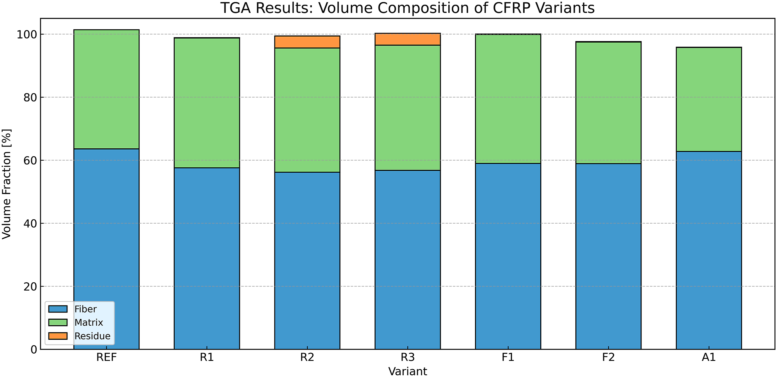
Across all tested variants, the fiber volume fraction (FVF) ranged from approximately 56% to 64%. The reference system (REF) exhibited a fiber content of about 63%, confirming consistent impregnation and good manufacturing quality. Variant A1 reached a similarly high fiber content, which is likely due to the tight packing of the 36K filament bundle used in this configuration.
Variants R1, R2, and R3 showed slightly reduced fiber contents between 56% and 58%, along with increased matrix fractions. This can be attributed to the increased viscosity and reduced flowability of the modified resin systems during impregnation. Notably, R2 and R3 also contained measurable residual mass (approximately 3%), which consists of silica deriving from the resin modification with nanosilica.
The surface-modified fiber systems F1 and F2 showed balanced fiber-to-matrix ratios in the range of 59–60%, with no detectable residue. These results indicate stable processing despite the absence of commercial sizing and confirm that fiber desizing and chemical surface modification did not adversely affect overall laminate composition.
A consolidated interpretation of the mechanical, thermal, and physical test results in conjunction with microstructural observations is provided later.
Microstructural and void fraction analysis
To provide physical evidence supporting the assessment of laminate quality and to document microstructural features resulting from the manufacturing process, selected composite plates were analyzed by optical microscopy. Cross-sectional micrographs were prepared from representative regions of the flat laminates after curing and trimming. The analysis focused on the spatial distribution of fibers and matrix, the presence and morphology of voids, and the occurrence of resin-rich regions.
Optical microscopy was performed at a magnification of 10× for five material variants (REF, R1, R2, R3, and A1). For the chemically surface-modified fiber systems F1 and F2, cross-sectional microscopy was not conducted; instead, process-related fiber damage was documented visually during filament winding. All observations reported in this section are strictly descriptive. A consolidated interpretation in relation to the mechanical and thermal test results is provided later.
General microstructural features across variants
Across all investigated laminates, voids were predominantly observed in interlaminar regions between adjacent fiber layers, while the fiber layers themselves generally remained continuous. The morphology, spatial distribution, and frequency of voids varied significantly between the material variants. In addition, differences were observed in fiber alignment, local fiber packing, and the presence of resin-rich regions, depending on the matrix formulation and fiber system.
Reference and matrix-modified systems (REF, R1, R2, R3)
Figure 9 shows the microstructure of the reference laminate (REF). Representative cross-sectional optical micrograph of the reference laminate (REF) at a magnification of 10×.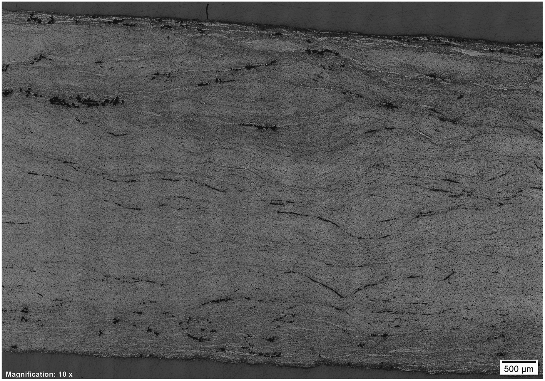
Void features are primarily present as elongated interlaminar voids aligned along the layer interfaces. No voids are observed within the fiber layers, and the void distribution appears relatively uniform across the laminate thickness. The porosity of the reference laminate was determined to be 3.54%.
In contrast, the silane-modified matrix system R1 (Figure 10) exhibits a markedly higher void population distributed throughout the laminate cross-section. Representative cross-sectional optical micrograph of the silane-modified matrix laminate (R1) at a magnification of 10×.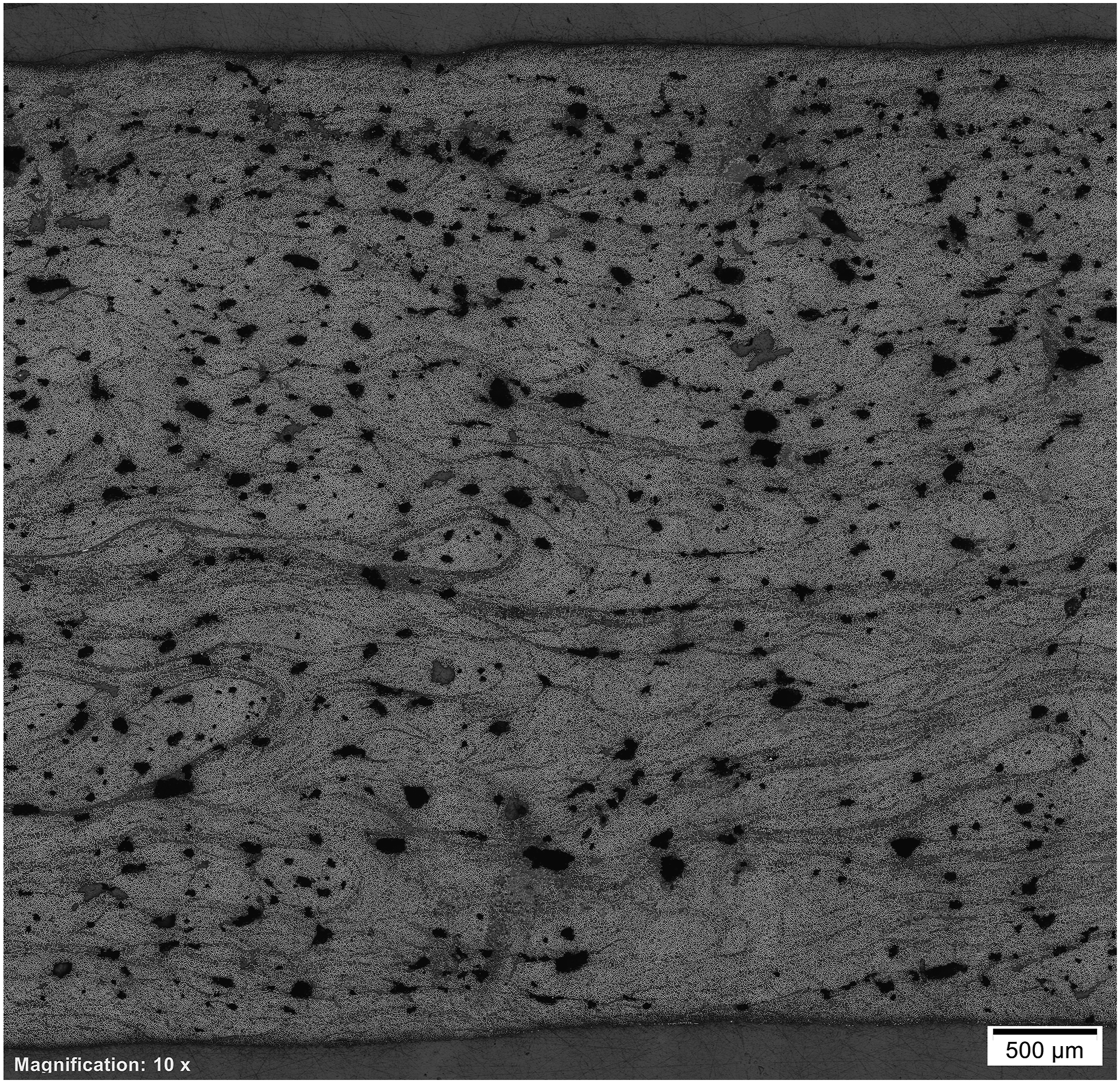
Void features vary in size and shape and are accompanied by streak-like structures and locally distorted fiber paths. Regions with increased resin content and reduced local fiber packing are observed. The porosity of R1 was measured at 12.97%.
The nanofiller-modified laminate R2 (Figure 11) shows a non-uniform void distribution across the laminate thickness. Representative cross-sectional optical micrograph of the nanofiller-modified matrix laminate (R2) at a magnification of 10×.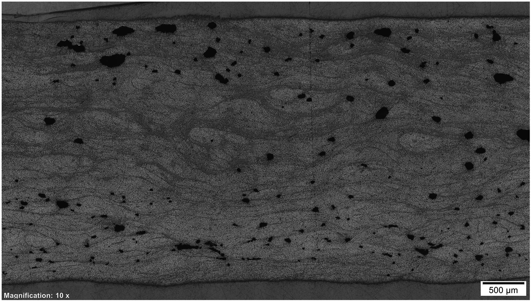
While relatively few voids are present in the central region, an increased void density is observed toward the laminate edges. The voids are predominantly interlaminar and exhibit a heterogeneous spatial distribution. The porosity of R2 was determined to be 15.57%.
The combined nanofiller- and silane-modified laminate R3 (Figure 12) exhibits the lowest void population among the matrix-modified systems. Representative cross-sectional optical micrograph of the nanofiller- and silane-modified matrix laminate (R3) at a magnification of 10×.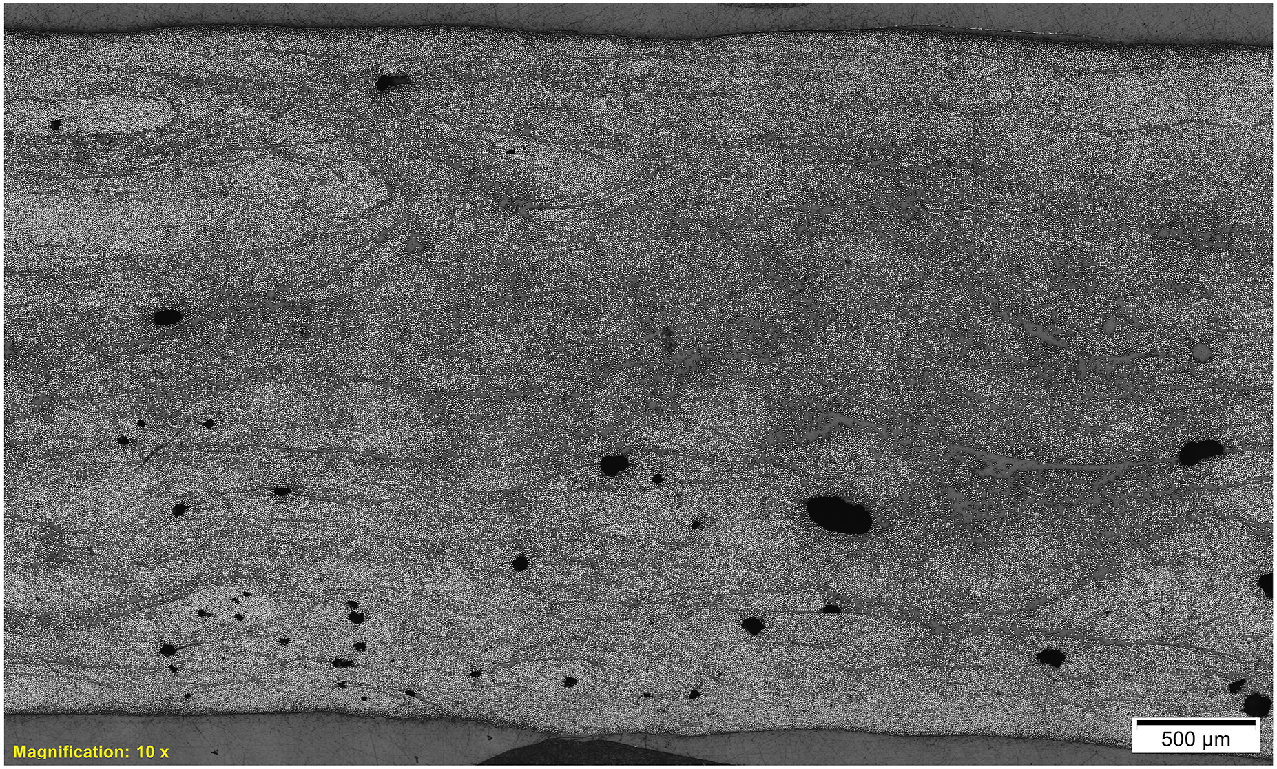
Void occurrences are sparse and mainly confined to isolated regions. In contrast, resin-rich zones are more pronounced and distributed between adjacent fiber layers. Despite the presence of resin-rich regions, the overall fiber and matrix distribution appears relatively uniform. The porosity of R3 was measured at 1.81%.
Alternative fiber system (A1)
Figure 13 shows the microstructure of the alternative fiber laminate A1 based on the T720 fiber system. Representative cross-sectional optical micrograph of the alternative fiber laminate (A1, T720 fiber system) at a magnification of 10×.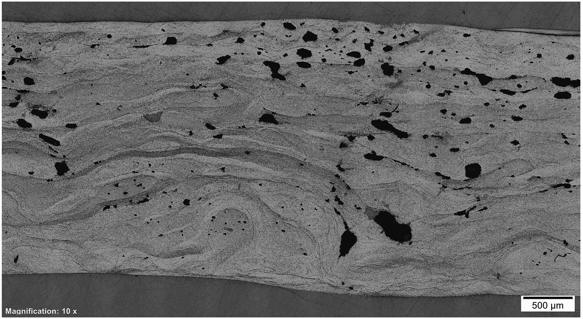
Void features are present across the laminate cross-section but occur less frequently than in the R1 laminate. However, individual voids appear larger in size and are predominantly located in interlaminar regions, with some voids extending across multiple layers. The fiber architecture shows locally compact fiber bundles adjacent to matrix-rich regions disrupted by larger voids. The porosity of the A1 laminate was determined to be 4.74%.
Process-related fiber damage observations (F1 and F2)
In addition to cross-sectional microscopy, process-related visual observations were documented for the chemically surface-modified fiber variants F1 and F2 during filament winding. Figure 14 shows the unwinding behavior of the treated carbon fiber roving during processing of specimen series F2. Visual documentation of process-related fiber damage during filament winding of chemically surface-modified carbon fiber variant F2. Pronounced fiber fuzz formation and filament protrusion are observed during unwinding of the treated roving, indicating advanced yarn damage and impaired handling behavior.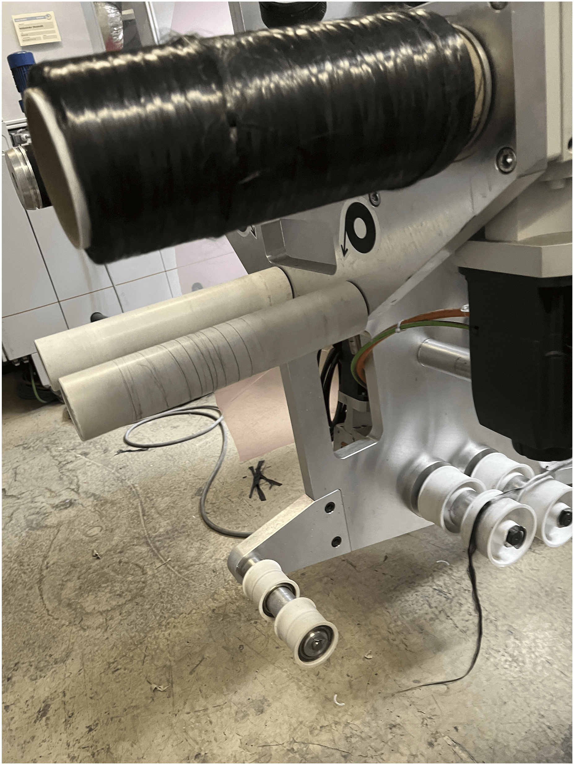
Pronounced fiber fuzz formation is visible during unwinding, indicating the presence of broken or damaged filaments protruding from the roving. The fiber surface appears irregular, and local filament bundles separate from the main roving, resulting in entanglement during handling and winding. The observed damage features correspond to advanced yarn damage levels reported and classified in the literature, ranging from protruding single broken filaments to bundles of broken filaments and partial yarn disintegration. Such damage states are associated with degraded fiber integrity and impaired handling behavior during composite processing. 35
Consolidated evaluation of test-based results
Variant-level interpretation
The mechanical and thermal test results place most material systems within a functionally comparable range, although none outperformed the reference configuration across all evaluated dimensions. Several variants exhibited isolated performance advantages; however, these were frequently accompanied by increased scatter or trade-offs in other performance domains. The following consolidated evaluation integrates the test-based results with the microstructural observations presented before to support a physically grounded interpretation of the observed performance trends.
The reference system (REF) displayed consistent mechanical behavior across all tests. Its relatively low porosity (3.54%) and uniform interlaminar void distribution confirm its robustness and suitability as an industrial baseline.
Among the matrix-modified systems, R3 achieved the strongest overall test-based performance, particularly in tensile and bending strength. This performance is consistent with the microstructural observations, where R3 exhibited the lowest porosity (1.81%) and a comparatively homogeneous fiber–matrix distribution. While resin-rich zones were observed, void occurrences were sparse and isolated, suggesting effective impregnation and load transfer at laminate level.
R2 reached similarly high tensile strength values but showed reduced stiffness and increased scatter. The non-uniform void distribution observed in the R2 micrographs, with elevated porosity toward laminate edges (15.57%), provides a plausible explanation for this less balanced mechanical response. These features indicate sensitivity to processing conditions and resin handling, which likely affected local laminate quality.
The silane-modified matrix system R1 exhibited stable but slightly reduced tensile performance compared to the reference. Microstructural analysis revealed a high void content (12.97%) and inhomogeneous fiber–matrix distribution, including streak-like features and resin-rich regions. These observations suggest that the potential benefits of improved interfacial chemistry were at least partially offset by laminate-level inhomogeneities under the applied processing conditions.
The chemically surface-modified fiber systems F1 and F2 did not deliver improvements in laminate-level mechanical performance. Tensile and bending strengths were significantly reduced compared to the reference. As documented in the microstructural and void fraction analysis section, pronounced fiber damage was observed during filament unwinding and handling, including fiber fuzz formation and filament breakage. These process-related defects are known to impair effective load transfer and reduce composite strength and are therefore considered a dominant factor governing the observed mechanical underperformance.
Despite employing a higher-strength carbon fiber, the alternative fiber system A1 showed reduced tensile and bending performance. Microstructural analysis revealed moderate porosity (4.74%) with fewer but larger interlaminar voids. These features, combined with the dense 36K tow architecture, suggest that impregnation quality and local stress concentrations limited the effective utilization of the enhanced fiber strength under the applied wet filament winding conditions.
Overall, the consolidated evaluation demonstrates that mechanical performance alone is insufficient to identify viable material candidates. Processing-induced microstructural features such as void distribution, fiber damage, and resin-rich regions strongly influence laminate-level behavior. Consequently, no configuration can be recommended or excluded based on test results alone, underscoring the necessity of complementing test-based findings with a structured criteria-based evaluation.
Role of processing and laminate quality
It is important to emphasize that many of the observed performance differences were strongly influenced by processing-related factors rather than intrinsic material properties alone. As demonstrated by the microstructural observations, variations in void content, void distribution, resin-rich regions, and fiber damage had a pronounced impact on laminate-level behavior.
In contrast, the reference system benefited from its established handling characteristics and proven compatibility with the wet filament winding process, resulting in a more consistent laminate microstructure and stable mechanical performance.
Thermal and physical screening results
Thermal and physical analyses confirmed that all investigated material systems achieved adequate curing behavior and fiber-to-matrix ratios. DSC measurements showed glass transition temperatures within the expected range for structural epoxy systems, and no indications of undercuring or incomplete reaction were observed. TGA results confirmed fiber volume fractions within a comparable range across all variants, without excessive deviation.
Accordingly, none of the tested configurations was excluded based on thermal or compositional criteria, and all variants were considered suitable for inclusion in the subsequent evaluation.
Implications for evaluation framework and Axis 1
Given the relatively small differences in mechanical performance and the strong sensitivity of laminate properties to manufacturing conditions, no configuration can be recommended or ruled out based on test results alone. This highlights the necessity of complementing test-based findings with a criteria-based evaluation to assess industrial viability.
To support this integration, the mechanical test results were consolidated into a unified performance index. Tensile strength, bending strength, and flexural modulus were normalized on a relative 0 to 5 scale within the investigated dataset, with the best-performing variant assigned a score of 5. Interlaminar shear strength (ILSS) was excluded from the composite score due to minimal variation between variants. Thermal and physical results served exclusively as screening criteria to verify curing and composition and did not influence the scoring, as no failures were observed in these domains.
The resulting “Mechanical Performance” index forms one axis of the combined radar chart presented in the material screening matrix section. The normalized index is used solely for comparative visualization within the defined design space and does not replace the interpretation of absolute property values and trends discussed above.
Criteria-based evaluation
In addition to the mechanical and thermal results, this section focuses on the criteria-based assessment of the investigated material systems. While test-based performance is essential for evaluating structural integrity, other dimensions such as process integration, cost-efficiency, and regulatory alignment play an equally critical role in determining industrial viability. These aspects are particularly relevant in early development stages, where only a small number of candidates can be advanced toward full-scale validation and implementation.
As introduced in the criteria-based evaluation section, six criteria were defined to capture the broader industrial relevance of each configuration: Processability and Process Changes, Technological Readiness, Scalability, Cost and Availability, Sustainability, and Regulatory Compatibility. Each criterion is scored on a uniform 0 to 5 scale, following established multi-criteria decision-making (MCDM) practices used in early-stage materials screening. 31
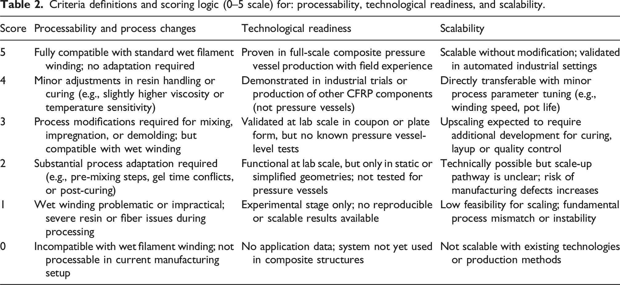
Criteria definitions and scoring logic (0–5 scale) for: processability, technological readiness, and scalability.
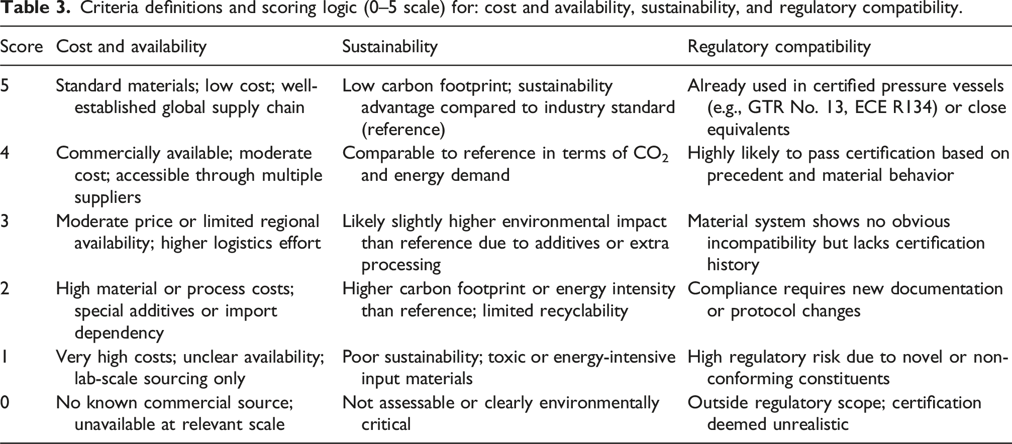
Criteria definitions and scoring logic (0–5 scale) for: cost and availability, sustainability, and regulatory compatibility.
Overview of criteria-based scores assigned to each material variant based on the six evaluation criteria. Scores range from 0 (least favorable) to 5 (most favorable) and are based on supplier data, literature, expert consultation, and manufacturing experience.
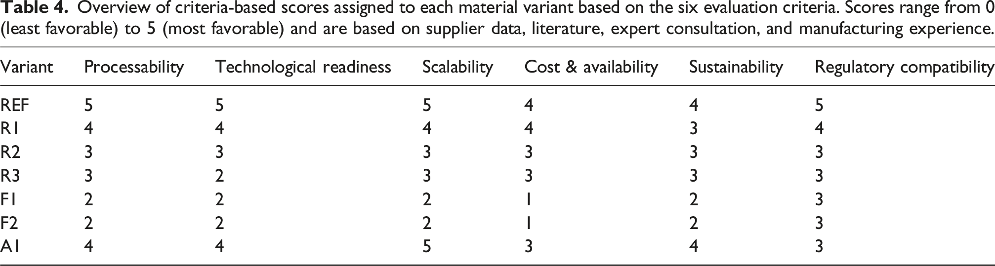
The two tables are structured by evaluation criterion and scoring level, ranging from 0 (least favorable) to 5 (most favorable). Each cell describes the criteria-based condition corresponding to its score, providing a transparent and reproducible basis for assessing the seven material variants summarized in Table 4. No weighting factors were applied at this stage to maintain an unbiased screening baseline. The detailed criteria-based scores for each variant are elaborated in the following sections.
Reference system (REF)
The reference system (REF) represents a widely adopted material configuration in the commercial production of Type IV hydrogen pressure vessels. It combines Torayca® T700SC-24K-50 C carbon fibers with the epoxy matrix system ARALDITE® LY 1135-1A/ARADUR® 917-1 and Accelerator 960-1 from Huntsman. This combination is fully compatible with wet filament winding and has been used in certified high-pressure pressure vessels, enabling it to score 5 in processability, technological readiness, scalability, and regulatory compatibility.2,5,17
Due to its commercial status, the system is also broadly available through established supply chains. However, it should be noted that high-performance carbon fibers and epoxy systems remain cost-intensive compared to commodity-grade alternatives. Therefore, a slightly reduced score of 4 is assigned for cost and availability to reflect their specialized nature.
In terms of sustainability, the reference system serves as the baseline. While no additional additives or resource-intensive processes are involved, it relies entirely on fossil-based materials with a high embodied energy, especially the carbon fiber component. Moreover, some alternative configurations in this study aim to reduce fiber usage, which may improve overall environmental impact. Accordingly, a sustainability score of 4 is assigned to represent a neutral but non-optimized environmental footprint.
Silane-modified matrix (R1)
The R1 variant combines the reference epoxy matrix system with Dynasylan® GLYEO, a commercially available silane coupling agent. The additive was incorporated into the resin component and successfully processed under standard wet filament winding conditions. As confirmed during plate manufacturing for this study, the additional silane component had no substantial impact on handling, degassing, or impregnation behavior. Processability is therefore rated as 4, reflecting minor but manageable adjustments to the resin formulation.
Dynasylan® GLYEO is widely used as an adhesion promoter in epoxy-based systems and has demonstrated compatibility with both fiber surfaces and bulk matrix modifications. While not specifically validated for high-pressure vessel use, it is used in industrial composites, supporting a technological readiness score of 4. Scalability is likewise rated 4, as the additive is compatible with existing dosing and mixing equipment and does not require process changes beyond formulation mixing. 18
Cost and availability are rated at 4, in alignment with the reference system. The additive is available from multiple suppliers and used in industrial practice, but incurs low additional cost compared to unmodified epoxy formulations. For sustainability, a score of 3 is assigned. The inclusion of a synthetic organosilane introduces slight additional environmental complexity compared to the baseline resin. 18
From a regulatory perspective, the matrix system remains epoxy-based and free of reactive chemistries that would compromise certification. A score of 4 is assigned, reflecting high compatibility with certification frameworks while acknowledging the absence of direct use cases in certified pressure vessels.
Nanofiller matrix (R2)
The R2 configuration replaces the reference epoxy resin with ALBIDUR® F061, a nanofiller-modified epoxy system containing silica nanoparticles and polysiloxane core shell particles. While the material was successfully processed into plates, its practical implementation revealed multiple challenges that reduce its industrial applicability.
The base resin exhibited significant viscosity-related difficulties during processing. As reported in both manufacturing phases, ALBIDUR® F061 was highly sensitive to temperature, prone to separation during storage, and difficult to mix homogeneously. Solid particles remained visible even after extended gas removal times, and foaming behavior complicated handling. Additionally, degassing required 45 to 60 min, which is impractical for efficient process management, particularly due to the increased viscosity at processing conditions compared to the reference. Consequently, processability is rated at 3, reflecting the need for substantial adaptation and careful thermal control.
Due to these handling issues and the absence of prior use in hydrogen pressure vessel applications, the system’s technological readiness and scalability are also rated 3. Although ALBIDUR® F061 is commercially available and marketed for high-performance applications, its successful implementation in pressure vessel production would require further development—especially regarding its reproducibility and cure reliability in thick laminates.19,20 Several plates produced with this resin exhibited internal cavities and incomplete curing, even after prolonged heat treatment, limiting their usability for testing.
Cost and availability are likewise rated at 3. While the material is obtainable from established suppliers, it represents a specialty resin with integrated nanostructures and therefore incurs a cost and sourcing premium compared to conventional epoxy systems. In terms of sustainability, the embedded nanophases increase the overall material complexity and embodied energy, justifying a sustainability rating of 3.
The resin remains chemically within the scope of conventional epoxy systems, which supports a regulatory compatibility score of 3. However, due to the presence of functional fillers and the lack of precedent in certified pressure vessel systems, additional validation efforts would likely be required for implementation in regulated environments.
Combined nanofiller and silane matrix (R3)
The R3 variant integrates two modification strategies by combining the nanofiller-modified epoxy resin ALBIDUR® F061 with the silane-based coupling agent Dynasylan® GLYEO. Both components are individually compatible with epoxy systems, but their combined use introduces a higher level of formulation complexity.
During manufacturing, the integrated system caused several challenges. The base resin ALBIDUR® F061 displayed strong sensitivity to temperature and shear, while also showing signs of phase separation and incomplete gas removal. The addition of silane did not significantly mitigate these effects but also did not render the system incompatible with wet filament winding. As such, processability is rated at 3, reflecting the need for controlled mixing and resin handling while maintaining industrial feasibility.
From a technological readiness perspective, the formulation represents an experimental combination without documented prior use in structural composite components or pressure vessels. Both ALBIDUR and Dynasylan® are industrially marketed, but the absence of precedent for their combination in CFRP pressure vessels justifies a technology readiness rating of 2.18,19 Scalability is rated at 3, as no new process steps or equipment are required beyond precise dosing and ensuring homogenous dispersion.
The cost and availability score is set to 3. Although both components are commercially available and used in industrial applications, their combined use entails slightly higher formulation effort and material costs, without presenting supply chain risks or specialized sourcing requirements. Sustainability is rated at 3 due to the increased material complexity and the use of synthetic additives. Finally, regulatory compatibility is rated at 3. While the formulation deviates from standard matrix systems, it remains within the epoxy resin family and does not introduce reactive or toxic components that would inherently conflict with hydrogen pressure vessel certification pathways.
Amine-functionalized fibers (F1)
The F1 variant uses carbon fibers that have been chemically modified with aromatic amine groups to enhance interfacial adhesion with the epoxy matrix. The functionalization was achieved via diazonium-based electrochemical grafting, in which thermally desized T700SC-12K-50C fibers were treated with in situ generated nitrophenyl diazonium salts, followed by partial reduction to amino functionalities. The process was conducted at a research line under controlled voltage and residence time, producing small batches of spooled fiber for experimental use.
Although the grafting technique effectively introduced amine functionalities, as verified by nitrogen signals in the XPS analysis, challenges arose during the processing and integration of the modified fibers into CFRP laminates. During wet filament winding, the modified fibers exhibited increased brittleness and resin uptake, leading to occasional fiber breakage and elevated resin loss in the winding equipment. The overall process remained compatible with wet winding but required significantly reduced winding speeds and careful handling. Based on these factors, processability is rated at 2, reflecting substantial but not prohibitive process modifications.
In terms of technological readiness and scalability, the system remains at a laboratory demonstration level. While amine-functionalized fibers have been shown to enhance interfacial strength in academic studies, 21 they are not currently available as commercial products for pressure vessel applications. The chemical grafting process is not yet compatible with high-throughput production and was conducted at a research facility. Both technology readiness and scalability are therefore rated at 2.
Cost and availability are rated at 1, as the fibers were custom-made using resource-intensive methods and are not commercially available in meaningful quantities. Sustainability is rated at 2, due to the use of thermal desizing, chemical baths, and electrochemical grafting—all of which add complexity, energy input, and chemical waste.
From a regulatory standpoint, the system remains within the epoxy-CFRP framework and does not introduce novel resin chemistries. However, the use of modified fibers with chemically active groups may require additional certification testing. As such, regulatory compatibility is rated at 3.
Phenol-functionalized fibers (F2)
The F2 variant uses carbon fibers modified with phenol groups to enhance fiber–matrix adhesion. Similar to F1, the modification was achieved via diazonium-based electrochemical surface grafting. In this case, phenol-functional diazonium salts were grafted onto thermally desized T700SC-12K-50C fibers, using a continuous electrochemical process. This procedure involved high-temperature desizing, electrochemical reduction, and spooling of modified fibers.
The phenol-grafted fibers were processed using wet filament winding with the standard epoxy matrix system. However, practical issues arose during production, including increased resin uptake, dripping resin accumulation on machine components, and brittle handling behavior of the treated fibers. These effects required reduced winding speed and cautious material handling. Processability via filament winding is rated 2, reflecting the substantial effort required for adaptation, including, for example, optimizing spreading, impregnation techniques, and preventing fiber damage or defects.
Technological readiness and scalability are each rated at 2. The modification process is experimental, and no known applications of phenol-functionalized fibers exist in certified structural composites. While the grafting technique was implemented successfully on a research line, it is not compatible with current industrial fiber production speeds or in-line equipment.
The cost and availability score is set at 1, as the fibers were produced on a non-commercial scale with high labor and process input and are not yet available through any supply chain. Sustainability is rated at 2 due to the cumulative energy and chemical demand of the surface modification process.
From a regulatory perspective, the system remains within the general framework of epoxy-based CFRP. Although the fiber surface has been chemically modified, the functional groups introduced (phenolic) are not expected to introduce hazardous reactivity. As such, regulatory compatibility is rated at 3.
Alternative fiber system (A1)
The A1 configuration replaces the standard Torayca® T700SC-24K-50C carbon fiber with Torayca® T720SC-36K-50C, a high-strength fiber grade offering approximately 20% higher tensile strength while maintaining a comparable modulus. 16 The goal of this substitution is to enable equivalent or improved composite performance at lower fiber volume fractions, potentially reducing both material cost and structural weight in hydrogen pressure vessels.
During manufacturing, the T720 fibers were processed using the same epoxy matrix and wet filament winding setup as the reference configuration. While the winding process itself did not require major adaptations, the 36K filament bundles exhibited slightly different impregnation behavior. Specifically, the plates showed increased resin uptake, and some specimens revealed localized inhomogeneities and elevated variability in tensile strength results. These effects are attributed to the tighter fiber packing and limited resin flow between filaments, which necessitate minor adjustments in winding parameters and degassing procedures. Based on these factors, processability is rated at 4.
Technological readiness is rated at 4, reflecting the industrial availability of T720 carbon fibers and their documented use in high-performance composites. However, no explicit application in certified 700 bar Type IV hydrogen pressure vessels was found, which limits the rating. Scalability is rated at 5, as the material is compatible with automated winding equipment and is available in large spool formats. No additional processing steps are required.
Cost and availability are rated at 3. T720 or comparable fibers are more expensive than standard T700 grades and are currently offered by a limited number of suppliers. Still, they are commercially accessible and available in industrial volumes. Sustainability is rated at 4, as the manufacturing processes for T720 fibers are comparable to the reference T700, implying a similar environmental footprint in terms of CO2 and energy demand.
From a regulatory perspective, the fiber remains within the established category of PAN-based carbon reinforcements. However, the lack of precedent in certified pressure vessel systems suggests that additional material qualification may be required. Accordingly, regulatory compatibility is rated at 3.
Combined ranking/material screening matrix
To support a holistic assessment of the investigated material systems, a combined radar chart was created that integrates both test-based and criteria-based evaluation. This approach aims to visualize the overall suitability of each configuration for use in Type IV hydrogen pressure vessels, considering not only mechanical performance but also industrial feasibility, cost, sustainability, and technological maturity. This method follows established multi-criteria decision-making approaches commonly used in engineering design and material screening. 31
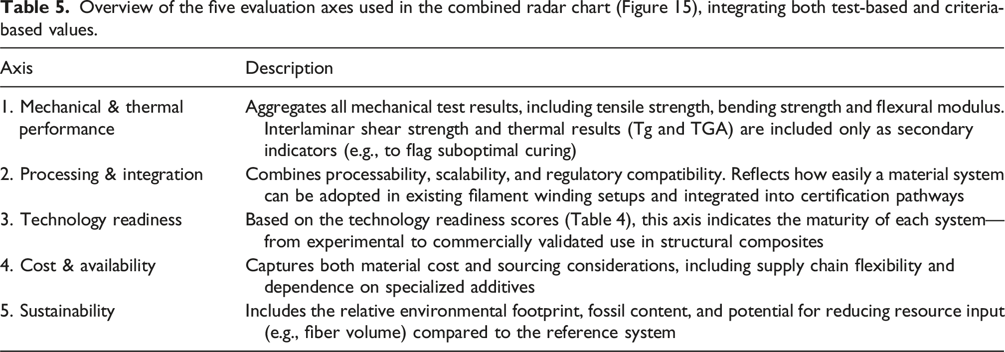
Overview of the five evaluation axes used in the combined radar chart (Figure 15), integrating both test-based and criteria-based values.
Each material variant was assigned a score from 0 to 5 along each axis, following the normalized scoring logic presented in Tables 2–4. No additional weighting was applied across criteria, as the focus of this study lies in early-stage screening rather than final design selection.
For axes 2 to 5, the scoring was derived from the criteria-based evaluation in Table 4. Axis 2 (Processing & Integration) was calculated as the average of the three contributing criteria—processability, scalability, and regulatory compatibility—while axes 3, 4, and 5 represent direct values from the respective categories: technological readiness, cost and availability, and sustainability.
Axis 1 (Mechanical & Thermal Performance) was calculated based on mechanical test results only, as thermal parameters (DSC and TGA) did not show significant variation and served merely as exclusion checks. The score reflects the average of three mechanical tests—tensile strength, bending strength and flexural modulus—all relevant for structural integrity in CFRP-based pressure vessels. Thermal properties (DSC and TGA) were used as qualification and exclusion checks to confirm sufficient curing and regulatory suitability but were not treated as linearly weighted performance parameters within Axis 1.
For each test, the best-performing variant within the investigated dataset received a score of 5, the lowest-performing variant a score of 0, and all others were scaled linearly in between. The normalized scores from these three tests were then averaged to calculate the final value for axis 1. Interlaminar shear strength (ILSS) was excluded from this composite score, as the results exhibited minimal variation across variants and were not deemed informative for overall performance ranking.
Normalized mechanical performance scores (axis 1) based on tensile strength, bending strength and flexural modulus. Values range from 0 (lowest-performing) to 5 (highest-performing).
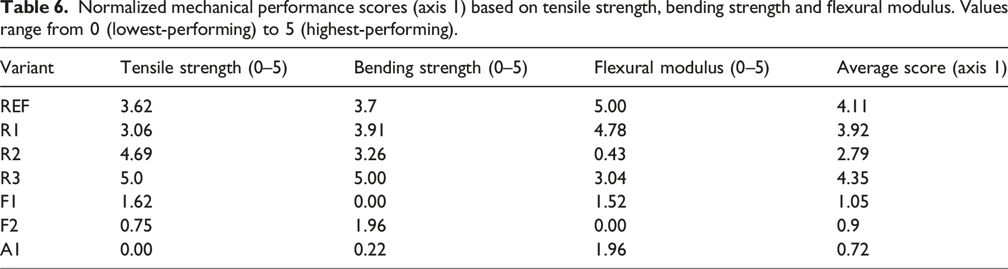
Among the tested systems, R3 achieved the highest overall score on Axis 1, confirming its strong performance across multiple structural properties. REF and R1 followed closely, with consistent and well-balanced results. R2 showed high tensile strength but was limited by reduced stiffness, indicating a less stable performance profile. The surface-functionalized fiber systems (F1 and F2) and the high-strength variant A1 reached the lowest scores. In all three cases, processing-related factors such as desizing, impregnation quality, or fiber damage likely prevented the intended material improvements from being realized at laminate level.
These scores illustrate that interface-level modifications or fiber upgrades alone are insufficient to ensure reliable improvements at the laminate scale. Structural performance remains sensitive to the balance of mechanical properties and to practical factors such as processing quality and matrix compatibility.
Figure 15 integrates the scores from all five axes into a single radar chart, enabling visual comparison of the full performance profiles across all material variants. The values are based on test-based (axis 1) and criteria-based assessment (axes 2–5) as detailed in Tables 4 and 6. Combined radar chart comparing all seven material variants across five evaluation axes: (1) Mechanical & Thermal Performance, (2) Processing & Integration, (3) Technology Readiness, (4) Cost & Availability, and (5) Sustainability. Scores range from 0 (least favorable) to 5 (most favorable) and were derived from a combination of test-based and criteria-based assessment. Marker points indicate axis-specific values; filled areas illustrate overall profiles.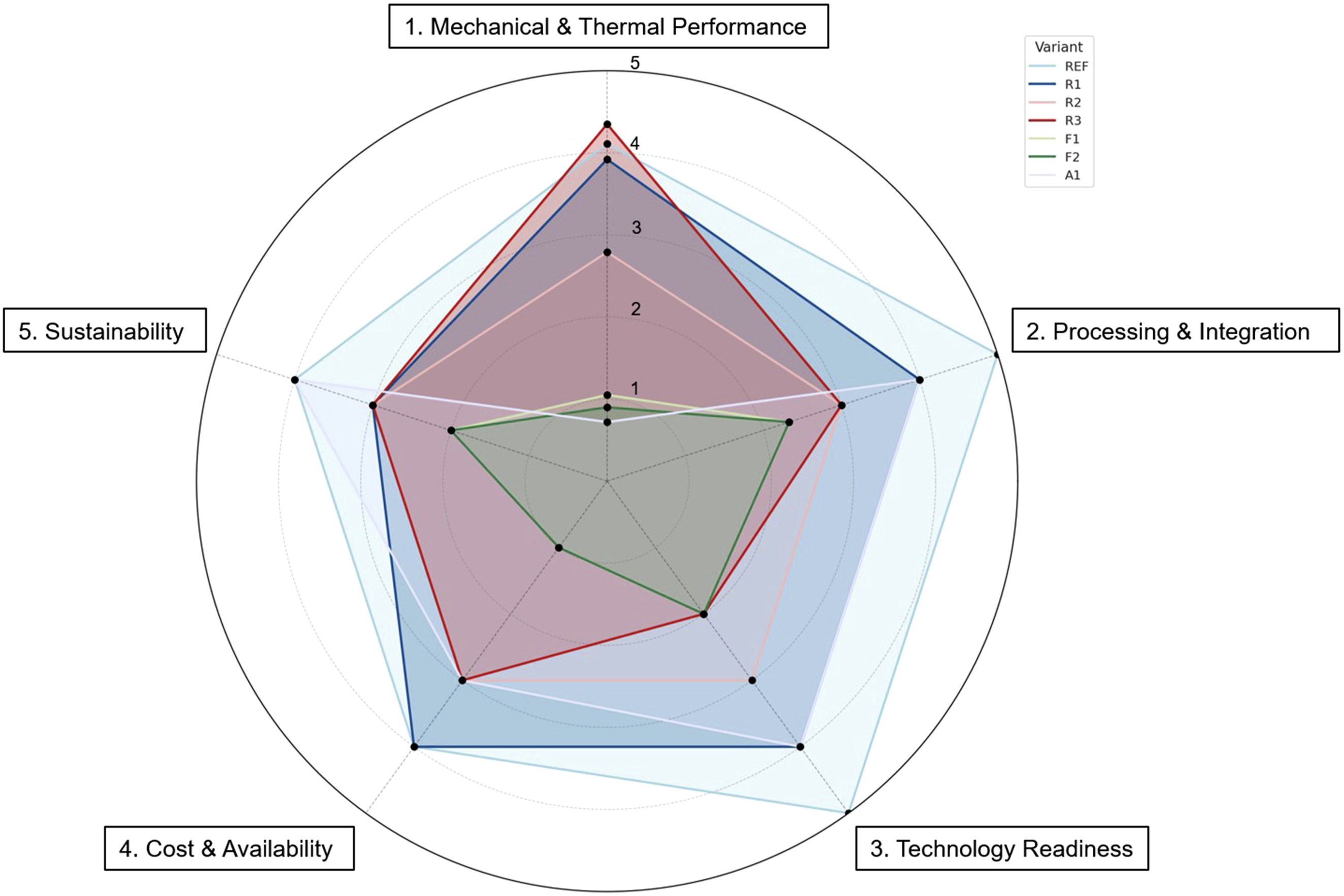
In this multi-criteria evaluation, each variant is represented as a polygon across the five axes, reflecting its relative performance on a normalized 0–5 scale. This enables a direct visual comparison of trade-offs and synergies among the different material strategies. The radar chart is used as a qualitative synthesis and visualization tool to highlight relative strengths, weaknesses, and trade-offs across different performance domains. The individual axes are not intended to be mathematically comparable or weighted against each other. This reflects the fundamentally different nature of quantitative test data and qualitative feasibility assessments. Instead, the chart provides an intuitive overview of how each material variant positions itself within the defined early-stage screening framework. Consequently, the numerical values shown in the radar chart should not be interpreted as absolute performance rankings across independent datasets.
R3 shows strong test-based performance but falls short in processing and readiness, limiting its implementation potential. REF presents the most balanced profile, while R1 offers a promising combination of mechanical and practical qualities. R2 demonstrates selective strengths but lacks consistency. The remaining variants F1, F2, and A1 score low across most axes, primarily due to processing limitations and underwhelming laminate-level performance.
The combined profiles underscore that strong performance in individual categories does not guarantee overall viability. Successful system selection depends on a balanced combination of structural performance, processing compatibility, and implementation potential.
Discussion
Interpretation of results
The combined evaluation reveals that only a few material variants achieve a well-balanced performance across all relevant dimensions. R3 stands out with the highest structural test performance, particularly in tensile and flexural strength. However, its limited scores in processing-related criteria and low technological readiness highlight a key limitation: strong test values alone are not sufficient if the formulation cannot be reliably scaled or integrated into existing manufacturing processes.
The reference system (REF) remains the most balanced configuration, with high and consistent scores across all axes. It combines established material properties with proven industrial compatibility, making it a dependable benchmark. R1 comes close in overall profile. Although it does not reach the peak mechanical scores of R3, it offers a favorable balance of process integration, availability, and sustainability, making it a realistic near-term optimization path without introducing significant risk.
R2 illustrates a common challenge in material development: selective improvements, in this case, tensile performance, can be offset by weaknesses in processability or material stability. This underscores the importance of viewing material systems as integrated entities, where individual gains must be considered in light of broader implications.
The surface-functionalized fiber variants (F1 and F2) and the high-strength fiber system (A1) show that conceptual advances do not necessarily lead to improved real-world performance. Despite promising ideas around interfacial adhesion or strength optimization, all three systems suffered from process-related drawbacks and failed to outperform the reference in any key area. This highlights how critical manufacturing compatibility is when moving from lab-scale innovation to applied composite design.
Taken together, these results reinforce the need for holistic evaluation frameworks when screening new material systems. Improvements in isolated performance categories may appear promising in early trials but often collapse when industrial feasibility is taken into account. Only those configurations that deliver well-rounded performance across structural, economic, and practical criteria should be advanced for further validation.
Addressing the research objectives
This study set out to explore alternative material configurations for CFRP-based Type IV hydrogen pressure vessels with the goal of reducing carbon fiber usage while maintaining sufficient structural and industrial performance. As outlined in the introduction, this ambition targets lower cost, increased vessel capacity, and improved sustainability for hydrogen storage systems in mobility applications.
The results show that this goal was only partially achieved. None of the tested variants outperformed the reference system in overall performance, and most did not reach comparable levels in mechanical balance or process robustness. Some enhancements were observed, particularly in the structural performance of R3 and the interface toughness and handling stability of R1, but these were typically accompanied by practical drawbacks such as high viscosity, limited scalability, or reduced readiness.
Nevertheless, the screening provided important insights. It confirmed the robustness of the reference system and clarified the narrow range in which meaningful improvements can be realized. The best-performing alternatives, R1 and R3, demonstrated that matrix modification can deliver tangible benefits, provided process integration and material compatibility are carefully managed. In contrast, surface-modified fibers and high-strength replacements like A1 did not translate their theoretical advantages into viable composite solutions under the tested conditions.
While no superior replacement was identified, the study yielded a validated and transferable evaluation framework structure that combines mechanical and thermal testing with criteria-based screening. This multi-dimensional approach enables efficient and transparent material selection within a defined design space and supports early-stage down-selection in development projects targeting high-performance composite structures, rather than providing universally applicable numerical performance thresholds.
Limitations
The findings presented in this study should be considered in the context of several limitations. The experimental work was carried out on flat plate laminates, rather than fully wound and cured composite pressure vessels. Although this approach facilitated systematic comparison under controlled conditions, it does not fully capture the geometric complexities, residual stress evolution, or in situ curing dynamics encountered in actual composite pressure vessels.
All processing steps were conducted at laboratory scale, where certain material variants posed practical challenges during mixing, degassing, and winding. These issues may manifest differently in industrial settings. The variability observed in some mechanical test results is likely influenced by such processing-related effects, rather than solely by the intrinsic properties of the materials. It is therefore conceivable that improved performance could be achieved under optimized industrial conditions, including automated dosing, tighter process control, and enhanced quality assurance. This is particularly relevant for matrix-modified systems, which demonstrated potential improvements in toughness and flexural strength but were affected by high viscosity or incomplete curing under lab-scale conditions.
The criteria-based evaluation framework applied in this study followed a structured and transparent methodology, yet it includes elements of expert judgment. Scoring in areas such as sustainability or regulatory alignment depended on available documentation and certain underlying assumptions. Further refinement of the data basis and decision metrics is recommended to support more objective and reproducible assessments in future work.
Despite these limitations, the combined evaluation approach remains a useful tool for early-stage material screening. It enables the identification of promising candidates and reveals potential trade-offs between mechanical performance and practical applicability. The trends observed can serve as a reliable basis for further development and industrial validation.
Conclusion
This study presented a structured screening of carbon fiber reinforced composite variants for application in Type IV hydrogen pressure vessels, with the goal of reducing carbon fiber usage while maintaining mechanical integrity and industrial applicability. Seven material systems were evaluated using a combined approach that integrated standardized mechanical testing with criteria-based assessment of processability, scalability, cost, sustainability, and regulatory compatibility.
Although the established reference system remained the most balanced and robust configuration overall, two alternative variants demonstrated promising characteristics in specific performance domains. The first, a silane-modified epoxy matrix system (R1), showed good mechanical performance combined with favorable processing behavior, availability, and sustainability. The second, a nanofiller- and silane-modified epoxy system (R3), achieved the highest structural performance in tensile and bending strength, although with notable limitations in process stability and readiness for industrial application, while still exhibiting glass transition temperatures within the established range for structural epoxy matrices and meeting the thermal qualification requirements for Type IV pressure vessels.
These findings underscore the need for holistic evaluation frameworks in composite development. High test-based performance alone does not guarantee industrial feasibility. Critical factors such as matrix handling, supply chain compatibility, and certification potential must also be addressed when selecting materials for hydrogen pressure vessels or other high-performance applications.
The combined screening approach applied in this work offers a transferable methodological framework for early-phase material selection, providing a structured and transparent evaluation logic whose methodological structure can be transferred to other material studies, while numerical results remain specific to the investigated design space. It enables transparent comparison across multiple technical and industrial criteria and can be adapted to other composite applications. Future work should explore hybrid strategies, refine interface modifications, and expand the framework to include life cycle metrics and component-level simulations.
In conclusion, advancing material systems for composite hydrogen storage requires both technical innovation and pragmatic consideration of industrial constraints. This study contributes to that objective by narrowing the field of viable candidates and providing a clear foundation for focused development and scale-up activities.
Footnotes
Acknowledgments
The authors would like to acknowledge the Faculty of Science, Engineering and Built Environment/Institute for Frontier Materials at Deakin University for providing the surface-treated carbon fibers used in this study. Special thanks go to Gabriel Eduardo Rojas Valenzuela, David Faron, and Sabrina Wirth from the Chair of Carbon Composites at the Technical University of Munich for their valuable support in the preparation and fabrication of test specimens, the execution of mechanical and thermal tests, and the processing of experimental data. During the preparation of this manuscript/study, the author(s) used OpenAI GPT-4/GPT-4o for the purposes of linguistic fine-tuning, stylistic refinement, format consistency, and the improvement of scientific expression and textual flow. The authors have reviewed and edited the output and take full responsibility for the content of this publication.
Author contributions
Conceptualization, N.R., Y.M., S.Z., and K.D.; methodology, N.R. and Y.M.; software, Y.M.; validation, N.R., Y.M. and S.S.; formal analysis, N.R., Y.M., S.S. and S.Z.; investigation, N.R., Y.M. and S.S.; resources, Y.M. and S.S.; data curation, N.R., Y.M. and S.S.; writing—original draft preparation, N.R.; writing—review and editing, Y.M., S.S. and S.Z.; visualization, N.R. and Y.M.; supervision, N.R. and K.D.; project administration, N.R., Y.M. and K.D.; funding acquisition, N.R., S.S., S.Z., and K.D. All authors have read and agreed to the published version of the manuscript.
Funding
The authors received no financial support for the research, authorship, and/or publication of this article.
Declaration of conflicting interests
The authors declared no potential conflicts of interest with respect to the research, authorship, and/or publication of this article.
Data Availability Statement
The original contributions presented in this study are included in the article. Further inquiries can be directed at the corresponding author.