
Abstract
In this study, the dispersion of reclaimed carbon fibres following cost-effective surface treatment is explored with a hydrodynamic fibre moving model, and a practical fibre dispersion effect is investigated through various physical dispersion methods. To utilise reclaimed carbon fibres for a desired composite product, our proposed low-cost surface treatment is shown to be beneficial to the physical and chemical properties of the reclaimed carbon fibres and to yield polar-hydrophilic characteristics. Single fibre tensile testing is performed to explore the effect of surface treatment on the reclaimed carbon fibres (a higher tensile strength was observed). A computational hydrodynamic fibre moving model based on a moving particle semi-implicit method is newly designed to perform hydrodynamic simulation to determine aqueous dispersion of discontinuous reclaimed carbon fibres. This simulation helps understanding fibre flocculation phenomena from the perspective of fibre stiffness, which should not be disregarded for the fibre dispersion. Fibre surface analyses including morphology and functional groups are carried out to investigate the effect of surface treatment. The hydrodynamic simulation and proposed fibre dispersion methods with a cost-effective surface treatment approach can be widely applicable to any type of reclaimed carbon fibres to produce recycled fibre reinforced polymer composite materials.
Introduction
Fibre reinforced polymer (FRP) composites are made from at least two constituent materials that are combined into a multi-phase material offering high strength and stiffness-to-weight ratio, and which are therefore used in various structural applications.1,2 FRP composites often consist of continuous or discontinuous carbon and glass fibres providing strength and stiffness to the composites, and synthetic organic or semi-organic matrices are mostly processed as thermoset or thermoplastic polymers to allow the composites to be set into the desired form.
Fibres, used as reinforcement, with thermoplastic composites have the potential to be more easily recycled and reprocessed than those of thermoset composites. Thermoplastic matrices are characterised as being re-melted and re-moulded with no degradation of the polymer chains, whereas thermoset matrices have a cross-linked structure that leads to irreversible and insoluble characteristics. 3 As such, thermoplastic matrices have been reprocessed by separating fibres with a variety of processes by controlling heat and pressure due to the intrinsic thermoplastic characteristics such as high melting temperature, high consolidation pressure and high viscosity. In contrast, thermoset matrices are widely used for composite engineering applications due to higher interfacial adhesion to fibres than thermoplastic matrices. This is because interphase region of the thermoset composite forms strong chemical bonds between the fibre and the matrix, whereas in thermoplastic composites, the thermoplastic matrix shrinks around the fibre and weak van der Waals bonds are formed at the fibre surface.4,5 When the fibres are reclaimed, the thermoset matrix is almost inevitably sacrificed, which is less attractive from the perspective of achieving a more sustainable product and promoting circularity.
The increase in use of FRP composites has led to a concomitant increase in waste production, and currently tonnes of end-of-life composites are disposed in landfill sites or incinerated. This is a critical issue for environmental and economic impact. Thus, the disposal process of composite wastes is more demanding than reproducing composites.6–9 According to the Composites Leadership Forum UK, in April 2021, the UK government set out its target to reduce carbon levels to 78% of those of 1990 to achieve ‘Net Zero’ by 2050. 10 To fulfil this aim, it is imperative that re-use or recycling technologies are now implemented to reduce the environmental impact associated with the FRP composites industry. Therefore, for the circular economy and zero carbon emission globally, recycling technologies for composites are now increasingly demanding as part of the energy-saving strategy.11,12
When considering how FRP composites are to be recycled, the first step is to reclaim fibrous reinforcements by separating them from the polymer matrices without causing damage to the fibres. Pyrolysis, fluidised bed, and combustion or incineration are currently used on varying industrial scales as reclamation methods to collect fibrous materials.3,13 In particular, the pyrolysis method is widely implemented in the composites industry for fibre reclamation by applying high temperature under a controlled atmosphere. This is often referred to as a thermal recycling technology involving resin decomposition and volatilisation to reduce the molecular weight of resin fragments using high thermal temperature (ca. 400–600°C) to break the char formed on the fibre surface and yield reclaimed fibres.3,14 However, during processing with the pyrolysis method, the reclaimed fibres tend to be highly entangled, making it necessary to separate and disperse the fibres at an early stage of the composite remanufacturing process prior to fibre alignment.
The High Performance Discontinuous Fibre (HiPerDiF) technology was invented in the University of Bristol and as a potential composite remanufacturing process to produce highly aligned discontinuous fibre prepreg tapes through fibre dispersion as shown in Figure 1. This technology involves a fibre-suspended water jet through a fibre alignment head and subsequent production of a highly aligned fibre preform and an ultimately prepreg,15,16 which has now been spun out as Lineat Composites (https://lineat.co.uk). The process is applicable to different types of fibres including natural and synthetic fibres as feedstock, but regardless of the fibres used, it is of critical importance that a stable fibre suspension is obtained. However, it is still challenging to get the stable fibre suspension because of various intrinsic physical and chemical properties of fibres. A schematic of the HiPerDiF (High Performance Discontinuous Fibre) technology.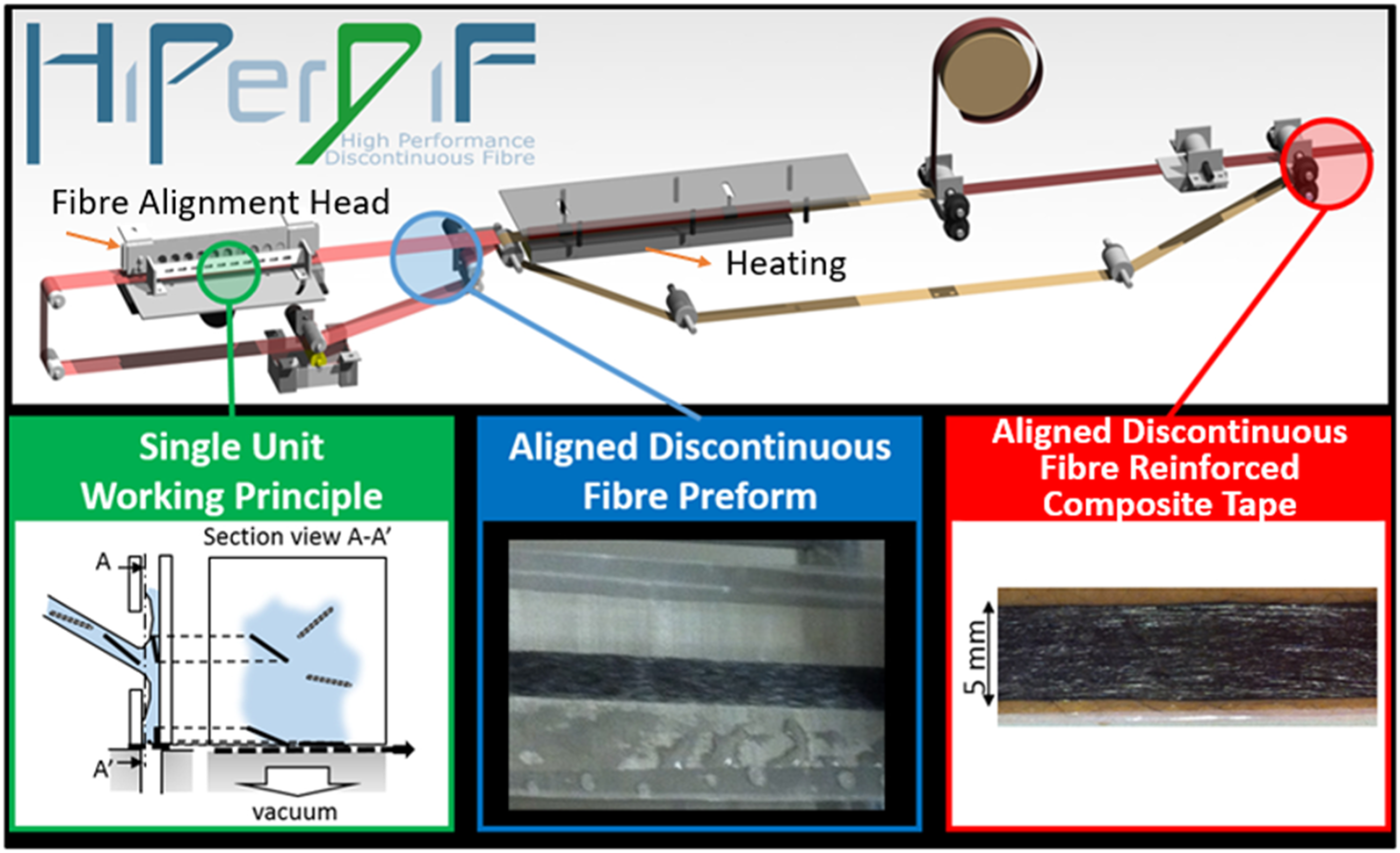
This study investigates the suspension of discontinuous reclaimed carbon fibres as a component of the advanced HiPerDiF technology. Achieving homogeneous fibre suspension is critical and challenging. However, we proposed a cost-effective method for obtaining a stable fibre suspension using fibre surface treatment in an aqueous medium environment. The primary limitation of this study is that it exclusively employs an aqueous medium for the fibre suspension. Nonetheless, the fibre suspension is effective in an aqueous medium environment, and the fibre alignment process has been developed as another component of the HiPerDiF technology. This technology can be widely applied to any type of fibres as long as surface-treated fibres are used, and it can impact recycling fibre reinforced composite structures through the use of discontinuous fibre prepreg tapes.
In this study, a cost-effective fibre surface treatment is designed under the aqueous medium environment, and the critical parameters to achieve a homogeneous and stable fibre dispersion are investigated. A hydrodynamic fibre moving simulation model is numerically newly designed using a moving particle semi-implicit method to investigate the fibre suspension. Furthermore, single fibre tensile testing is performed to explore the effect of the surface treatment of the reclaimed carbon fibres, and which is compared to virgin carbon fibres. Fibre surface analyses including morphology and element composition are carried out for reclaimed carbon fibres before and after surface treatment. The proposed low-cost surface treatment lies in tailoring reclaimed fibres with no detrimental effect on the fibre surface properties, and which is much more favourable compared to other more complicated and expensive chemical treatments disclosed in other literature (the detailed information is described in the sections of Materials and Surface treatment). Experimental results of fibre dispersion are discussed with computational simulations, and physical dispersion methods such as ultrasonication and high-shear mixing are additionally summarised with their respective mechanisms and characteristics.
Materials and methods
Materials
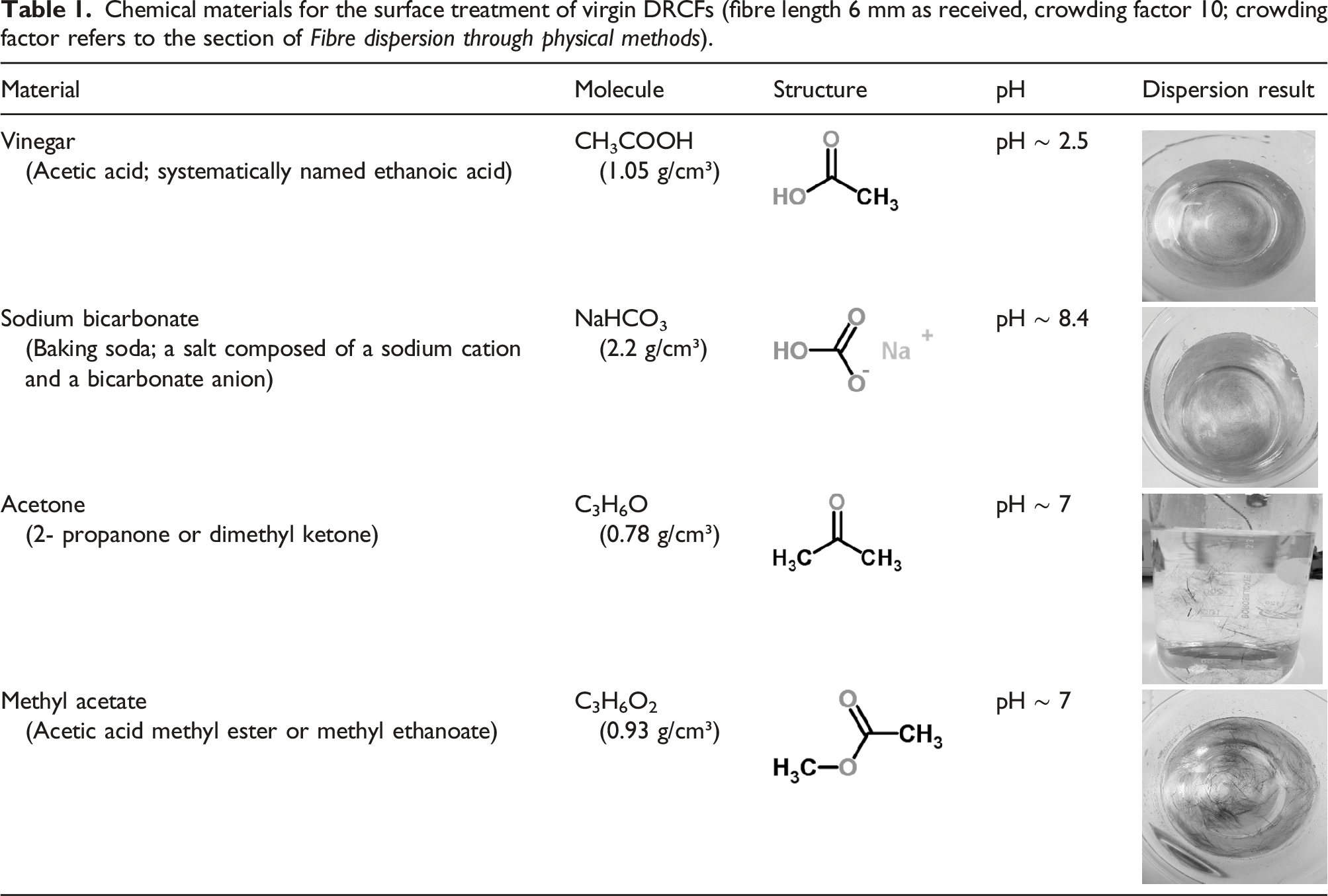
Discontinuous carbon fibre samples, reclaimed from end-of-life FRP composite materials using a commercial scaled pyrolysis process, were provided by ELG Carbon Fibre Ltd. (now renamed as Gen 2 Carbon Ltd., 2021). In this study, as lab-scale experiments, the surface treatment of the discontinuous reclaimed carbon fibres (DRCFs, that are 6 mm and longer in length as received; the longer DRCFs were treated with the optimised surface treatment and used for single fibre testing, which is referred to the section of Single fibre tensile performance) was performed via chemical treatment at different pH levels using various aqueous solutions of acetone, methyl acetate, vinegar and sodium bicarbonate. Acetone and methyl acetate solutions were obtained from Sigma-Aldrich, UK, while ethanoic acid (vinegar) and sodium bicarbonate powder (here, in the form of baking soda) were common household products. Aqueous solutions were prepared with vinegar (12% v/v), acetone (15% v/v), methyl acetate (15% v/v) and sodium bicarbonate (2% w/v). Tap water (pH 7.03 at 18.4°C) was used as solvent for each chemical concentration and as working fluid to investigate DRCFs dispersion before and after surface treatment. Tenax® short ‘water soluble’ carbon fibres (WSCFs) were obtained from Teijin Ltd. as the counterpart of DRCFs to compare fibre dispersion (N.B., the WSCFs are not literally soluble, but the term refers to a proprietary water-soluble sizing that is applied).
Surface treatment
The pyrolysed DRCFs used as received, and referred here as ‘virgin DRCFs’, were processed with surface treatment. The virgin DRCFs are inherently highly fluffy and entangled, so it is difficult to disperse them in water. In contrast, the commercial WSCFs with water-soluble sizing disperse well in water as their hydrophilic surface agents attract water molecules and facilitate hydrogen bonding, therefore leading to better fibre surface wetting. The main aim is to investigate fibre dispersion for the virgin DRCFs before and after surface treatment compared to WSCFs to yield relatively high fibre concentration and homogeneous suspension without fibre flocculation.
In this study, the surface treatment for the virgin DRCFs was carried out to increase surface polarity and the number of active sites on the fibres to yield surface wettability. This is due to the fact that the virgin DRCFs are pyrolysed and some impurities on the fibre surface are removed, thereby exhibiting a hydrophobic and relatively clean fibre surface.
The prepared chemical solutions are associated with alkalisation and acetylation modifications to remove undesired organic compounds and improve the wetting and adhesion properties of the virgin DRCFs by use of commodity chemicals, that is, acetic acid and sodium bicarbonate. Consequently, the dispersion in a fluid medium with the surface-treated DRCFs can be utilised via a simple and cost-effective way, which is competitive with other more complex and expensive chemical treatments. Surface-active agents in those solutions can contribute to the chemical functionalisation of the virgin DRCFs by creating functional groups on the fibres through the reaction of the hydrophilic and hydrophobic moieties. Consequently, hydrophilic fibres attract water molecules due to hydrogen bonds, and the fibre surface wetting promotes fibre dispersion.
Chemical materials for the surface treatment of virgin DRCFs (fibre length 6 mm as received, crowding factor 10; crowding factor refers to the section of Fibre dispersion through physical methods).
The further optimised surface treatment of the virgin DRCFs was observed after immersion in sodium bicarbonate solution (0.15 M) for 24 h. The chemical reaction of the virgin DRCFs in the sodium bicarbonate solution is shown in Figure 2. Chemical reaction of sodium bicarbonate to virgin DRCFs in water.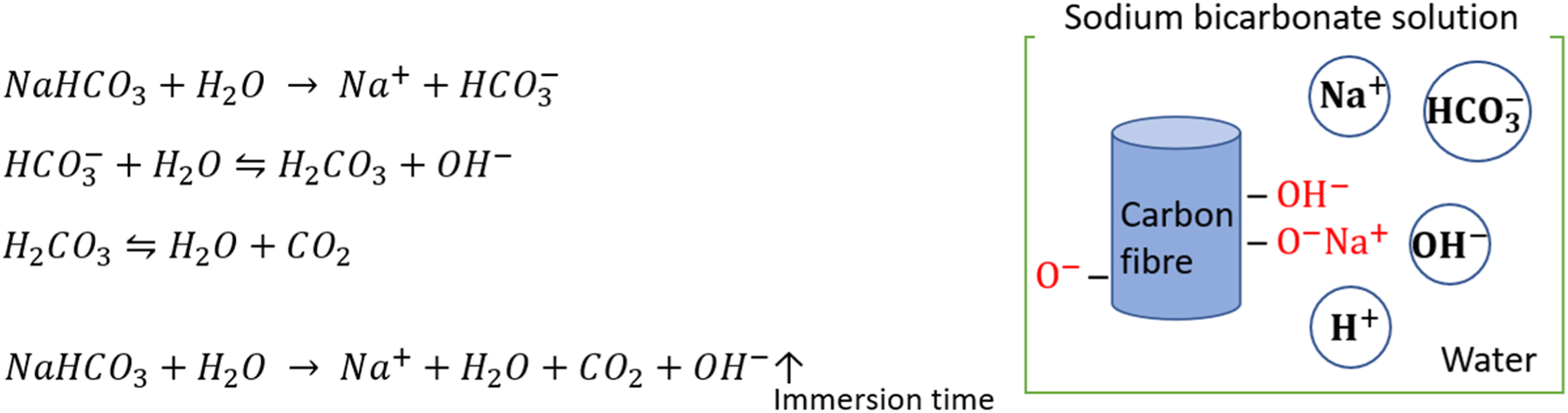
Sodium bicarbonate commonly consists of carbonic acid and hydroxide ion, and its aqueous solution performs as mildly alkaline. This surface treatment is designed to be a simple and cost-effective way to yield functional groups on the virgin DRCFs for the affinity to bond hydrogen molecules in water.
Characterisation
The surface morphology of the prepared fibres was determined by scanning electron microscopy (SEM; TM3030 Plus Tabletop, HITACHI, Berkshire, UK). The operating voltage of the machine was 15 kV, and the image resolution was adjusted corresponding to its magnification. Energy dispersive X-ray (EDX) spectroscopy was employed for investigating the change of elemental composition before and after surface treatment.
Fourier transform infrared spectroscopy (FTIR) was carried out with a PerkinElmer Spectrum 100 model. This is for the analysis of functional groups on the fibre surface using infrared spectroscopy (IR). In attenuated total reflectance mode, an IR spectrum resolution and its frequency ranges were adjusted to 1 cm−1 and 4000–600 cm−1, respectively.
Single fibre tensile testing was carried out using a Dia-Stron LEX 820 Extensometer machine (Dia-Stron Limited, Andover, UK) with a 20 N load cell. The surface-treated DRCF samples were prepared and set on the machine with a gauge length of 30 mm, in accordance with ASTM C 1557 standard. An ultraviolet curing adhesive, Dynamax 3139 adhesive, was used to consolidate the prepared single DRCFs at the end tabs. The single fibre diameter of the DRCF samples was measured at three different locations along the axial direction using an optical microscope (Zeiss Axio Imager M2). The mean diameter of the single fibre was used to calculate the axial tensile stress which results from the applied force divided by the cross-sectional area of the single fibre. During the test, the stress-strain graph was recorded with a crosshead speed of 0.02 mm/sec along the fibre direction until the fibre breakage was reached.
With the surface-treated DRCFs, a probe-type sonicator and a high-shear blending mixer as a physical dispersion method were used and compared each other for further fibre dispersion, respectively.
Computational fibre movement in a fluid
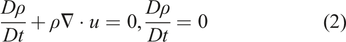
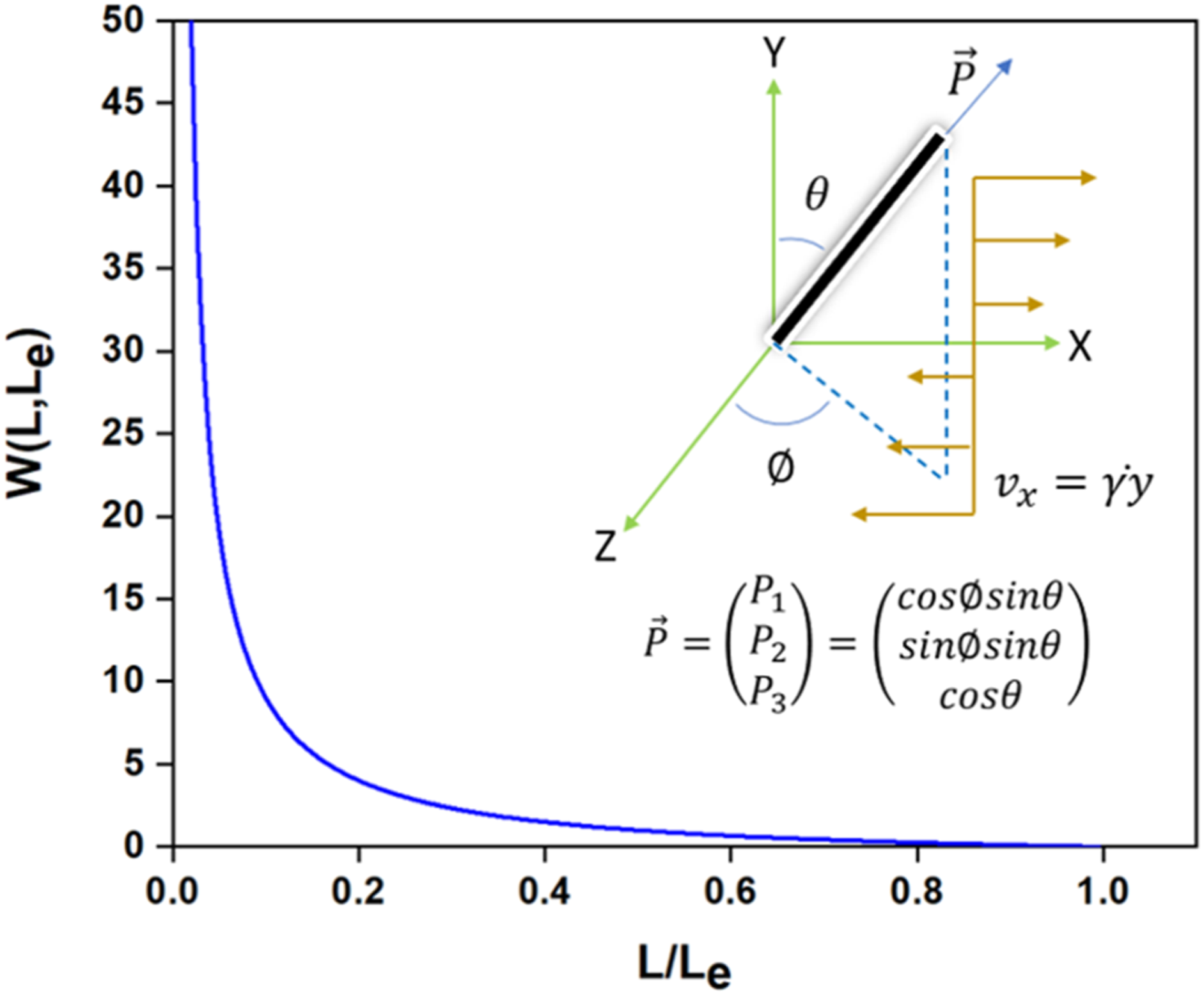
In fluid dynamics, Eulerian or Lagrangian methods are widely used in computational modelling of the particle transport and its distribution in an enclosed space. Eulerian methods are mostly used for fixed elements (volumes or points), whereas Lagrangian methods are to use elements (most usually points) that move with the flow velocity. In this study, a moving particle semi-implicit (MPS) method is used to investigate the effect of fibre dispersion, which is based on Lagrangian mesh-free particle tracking in an incompressible fluid phase. Fibre movement in an incompressible viscous fluid is described using Navier–Stokes and mass continuity equations as follows17,18: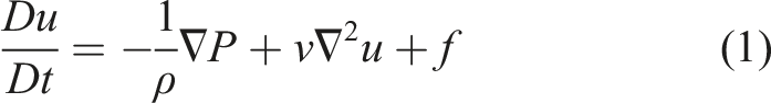
The MPS method for a particle 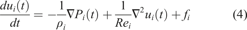
The weight function of fibre distribution in the MPS method can present the particle-to-particle interaction of fibres with the surrounding incompressible fluid particles.17–19 Weight function of the fibre distribution in the MPS method.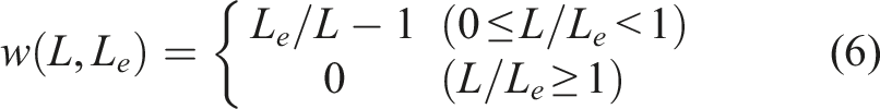
A dimensionless parameter, namely, fibre particle number density, 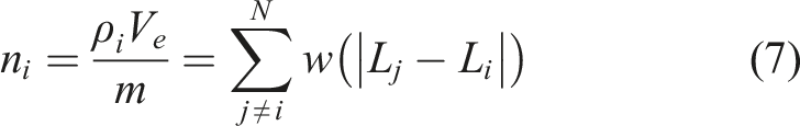
Results and discussion
SEM-EDX study
The simple and cost-effective surface treatment detailed in the section of Surface treatment was applied to the virgin DRCFs using a mild alkaline solution, that is, sodium bicarbonate solution at 0.15 M concentration. The surface morphology and element analysis are shown in Figures 4 and 5, which represent images of the fibre surface before and after surface treatment. The WSCFs, which were used as a counterpart to the DRCFs, are coated with a water-soluble binding agent. Hence, the treated WSCFs, that is, rinsed with water and dried, show an increase of surface roughness and a reduction in fibre diameter of 0.35%, following removal of the surface coating layer binding agent. In Figure 4, the virgin DRCFs show smooth and clean surfaces due to the pyrolysis process, whereas the surface-treated DRCFs display an increase in surface roughness, meaning that surface elements have changed as a result of the surface treatment. The surface element analysis was carried out using EDX. Surface morphology of WSCFs and DRCFs; (a) and (c) are virgin; (b) and (d) are treated with water and a mild alkaline solution, respectively. In particular, (b) is simply rinsed with water and dried. EDX spectra of DRCFs with different immersion time for the surface treatment; (a) indicates virgin DRCFs, and (b)–(f) are 3, 6, 24, 30 and 48 h immersion time at the 0.15 M of sodium bicarbonate solution, respectively.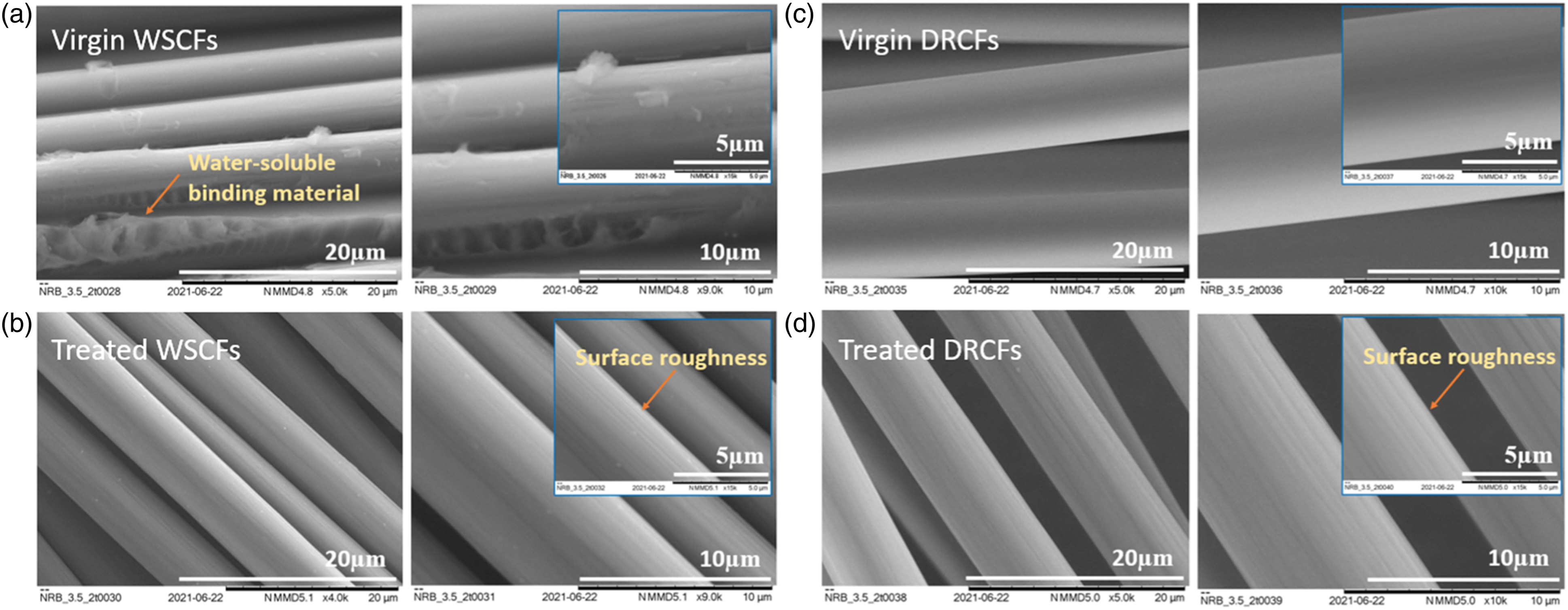
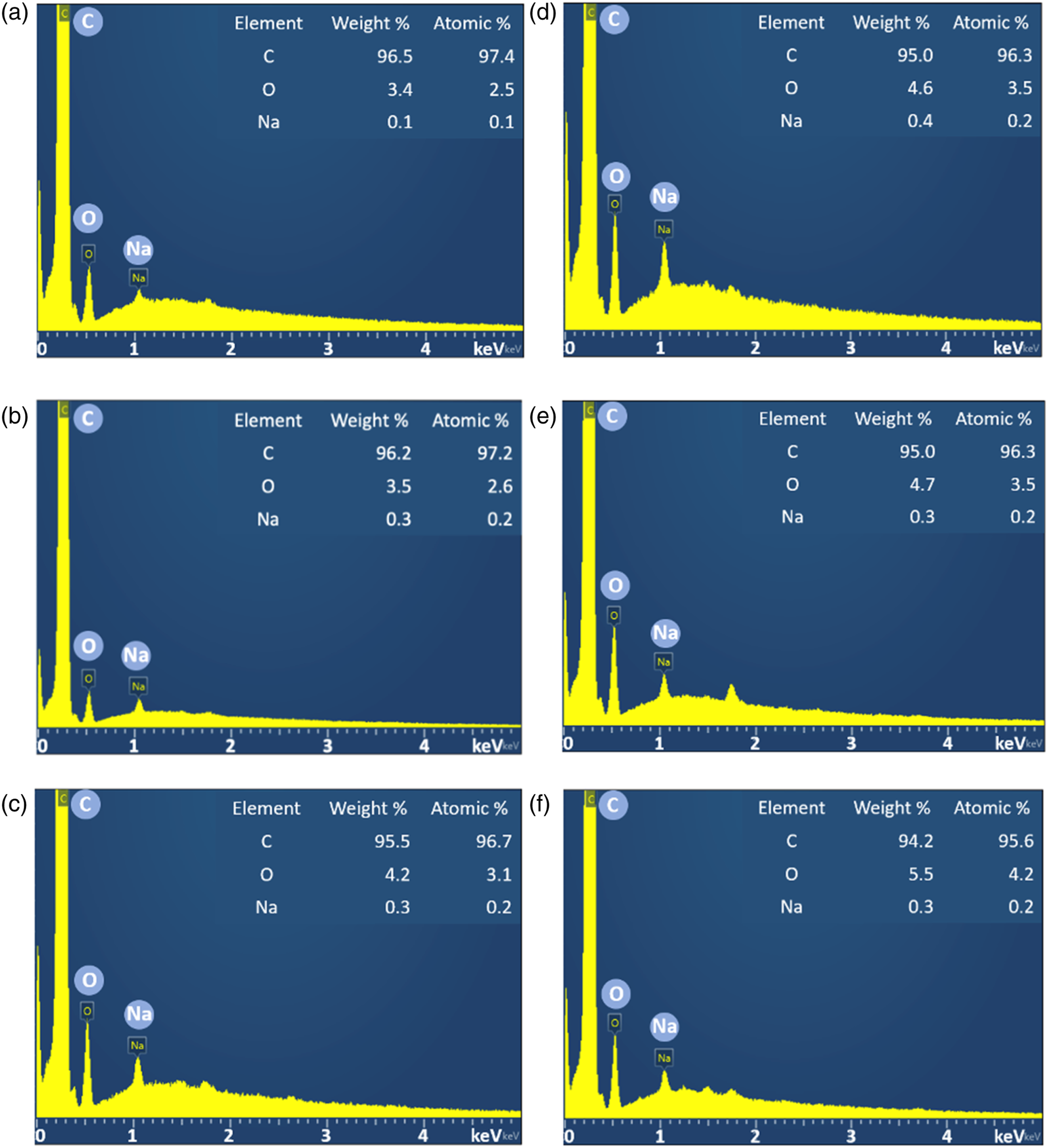
In Figure 5, the changes in element composition of the DRCF surface are identified as a function of immersion time, where the sodium bicarbonate solution was optimised at 0.15 M concentration. A weight percentage change of C, O and Na elements before and after surface treatment with the increase of immersion time is evident. According to the chemical reaction as shown in Figure 2, the presence of hydroxyl groups on the fibre increases with the immersion time. In Figure 5, the main elements that showed a weight percentage change were C and O. As the immersion time increased, the weight percentage of C decreased, while that of O increased. Although the weight percentage of the element Na was not significantly observed during the immersion time, it increased after 3 h immersion time for the surface treatment. The weight percentage of Na element after 3 h immersion time is the critical factor because the O–Na+ formation on the carbon fibre surface is varied, and the C element gradually decreases. As such, the surface morphology of DRCFs shows more roughness due to the decrease in the C element. Also, the lower percentage of C element results in a DRCF diameter decrease of about 0.28% when the immersion time was 24 h. The decreased fibre diameter can influence the fibre dispersion due to the higher aspect ratio with the same fibre length. Consequently, the surface treatment alters the reclaimed carbon fibre morphology and surface roughness. The use of mildly basic sodium bicarbonate is sufficient for the surface treatment of reclaimed fibres to increase the number of active sites (-H-C=O, -C-OH-, -O-C-, -C=O, -O-C=O) on the fibre surface to react with water molecules for the suspension, and resulting in no fibre flocculation. The further discussion is followed by sections.
FTIR spectral analysis
The presence of functional groups on the DRCFs after surface treatment were analysed using FTIR spectroscopy in the 4000–600 cm−1 range. In Figure 6, FTIR spectra were collected and compared with the different proportional transmittance and peak ranges of the prepared fibres by acquiring 16 co-added FTIR spectral scans. It is interesting to note that the functional groups are at 1465 cm−1 and 860 cm−1 (C–H bending) for the surface-treated DRCFs and at 1680 cm−1 (C = O stretching) for the virgin WSCFs due to the presence of a water-soluble binding agent. A very broad band characteristic of O–H stretch from polymeric hydroxyl groups was found in the 3550–3200 cm−1 range, where this is common to both surface-treated DRCFs and virgin WSCFs. Methylene groups (-CH2) were also commonly detected as a resolved combination of asymmetric and symmetric C–H stretches in the vicinity of 2925 cm−1 wavelength.
20
Characteristic vibrations were observed at 1420 cm− and 1268 cm−1 for the virgin WSCFS, which were attributed to O–H bending and C–O stretching, respectively. For the surface-treated DRCFs, O–H bending and vibration spectra were also broadly observed in the 1480–1400 cm−1 range,
20
corroborating the presence of the hydroxylic group. In short, the virgin WSCFs show predominantly bands due to conjugated C = O stretching on the fibre surface, whereas the surface-treated DRCFs show both C–H stretching and bending modes and O–H bending and vibration modes on the fibre surface. FTIR spectra for the prepared samples; virgin WSCFs are used for the counterpart of DRCFs to compare each other.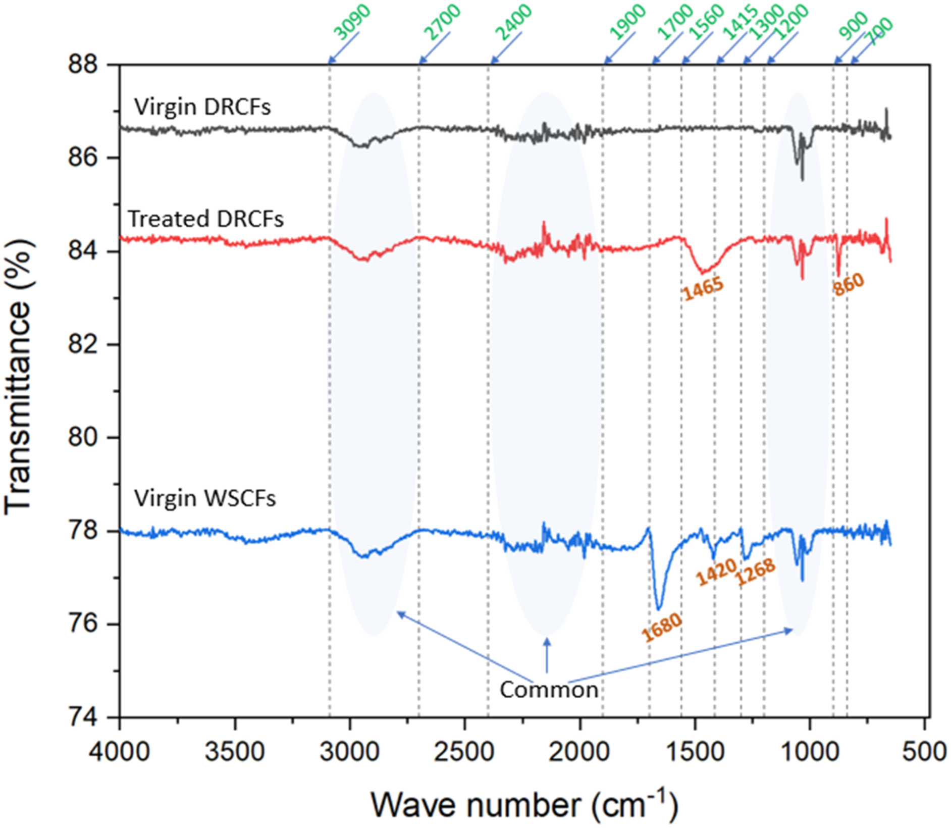
Figure 7(a) shows the FTIR transmittance spectra of both treated and virgin WSCFs in comparison with the virgin DRCFs. The FTIR transmittance spectra of the virgin DRCFs and the treated WSCFs are similar, as the water-soluble binding agent on the virgin WSCFs is dissolved during immersion in water; hence, there are no unique surface reactive sites remaining on the treated WSCFs, and therefore they become similar to virgin DRCFs. Figure 7(b) shows the effect on different molar concentrations of sodium bicarbonate and its surface functional groups. The increasing concentration of sodium bicarbonate applied to virgin DRCFs yields the same spectrum noting the same functional groups. FTIR spectra (a) to compare WSCFs before and after treatment and (b) to compare the effect of molar concentration on DRCFs.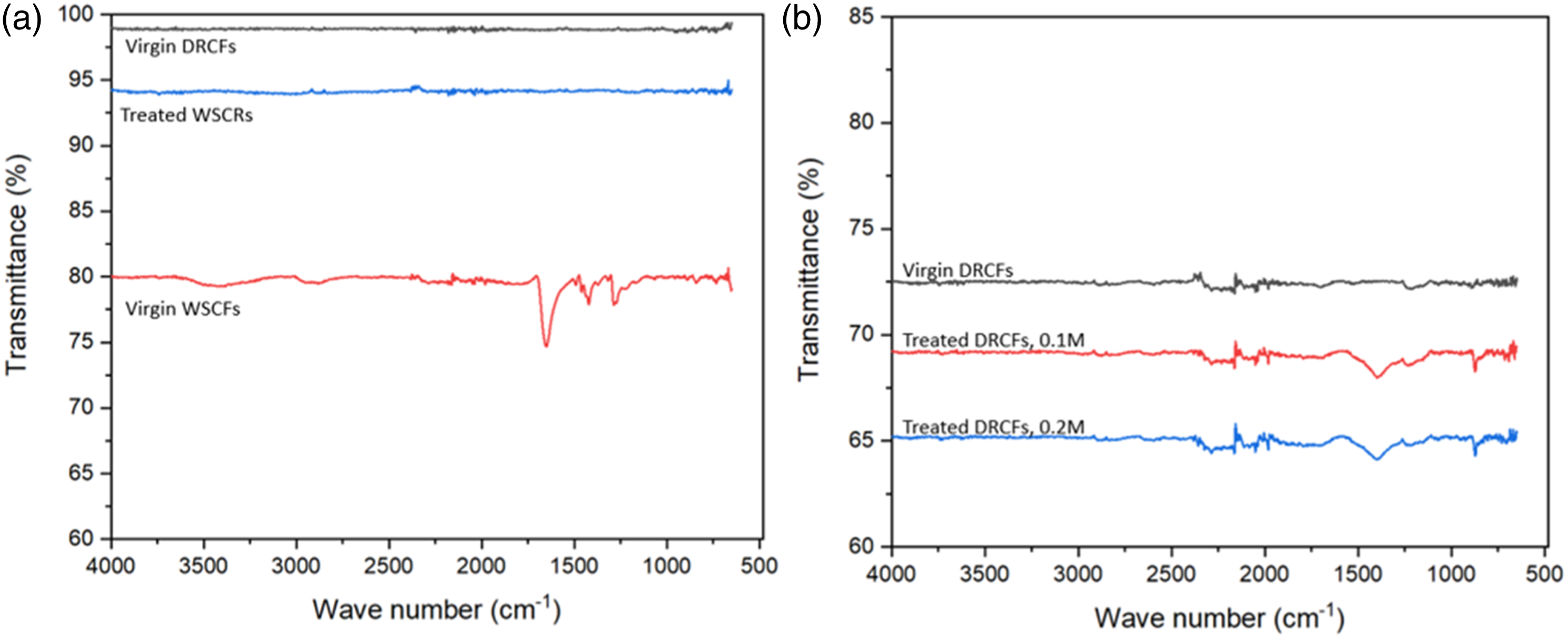
In Figure 6, the presence of hydroxyl groups on the treated DRCFs are evidenced by the presence of broad bands observed between 1480–1400 cm−1 as bending and vibration spectra, meaning that this is beneficial for fibre dispersion due to the presence of polar groups on the fibre surface yielding polar-hydrophilic characteristics. The presence of hydroxyl groups on the fibre leads to a hydrophilic behaviour improving dispersibility of the fibres through the formation of hydrogen bonds with water molecules. Therefore, polar-hydrophilic fibres can be obtained through a surface treatment based on a mild alkali solution from sodium bicarbonate.
Single fibre tensile performance
Single fibre tensile testing was conducted to investigate the effect of fibre surface treatment on the mechanical properties. Typical stress-strain graphs for DRCFs before and after optimised surface treatment are shown in Figure 8. The tensile stress is calculated from the mean diameter of each fibre (fibre cross-sectional area) and the applied loading force. The stress-strain graph shows an elastic-brittle behaviour. The test results and change ratios are summarised in Table 2. The chemical treatment does not change adversely the intrinsic elastic properties of the fibre. The surface-treated fibre shows a comparatively higher ultimate tensile strength. The axial modulus is observed at a little higher to the surface-treated fibre. The interesting finding is that the surface-treated fibre shows a modest increase in the axial modulus of 0.38%, while the change ratio of the ultimate tensile strength is incremental of 15.86%. This is caused by a reduction in the mean fibre diameter and in a chemical change of the fibre surface resulting in a weakening of the surface stress concentration and an increased resistance to the tensile force. Those ratios falling below 1% after surface treatment (and summarised in Table 2) are not significant. However, the data help to identify the optimised surface treatment proposed in our work by confirming which offer the most effective treatment to achieve strength against external load. Thus, it is evident that this optimised surface treatment does not adversely affect virgin type of reclaimed carbon fibres by creating active functional groups on the fibre surface due to a slight change in intrinsic physiochemical properties. Stress-strain plots of (a) virgin DRCFs and (b) surface-treated DRCFs using single fibre tensile testing. Single fibre tensile testing results with virgin and surface-treated DRCFs.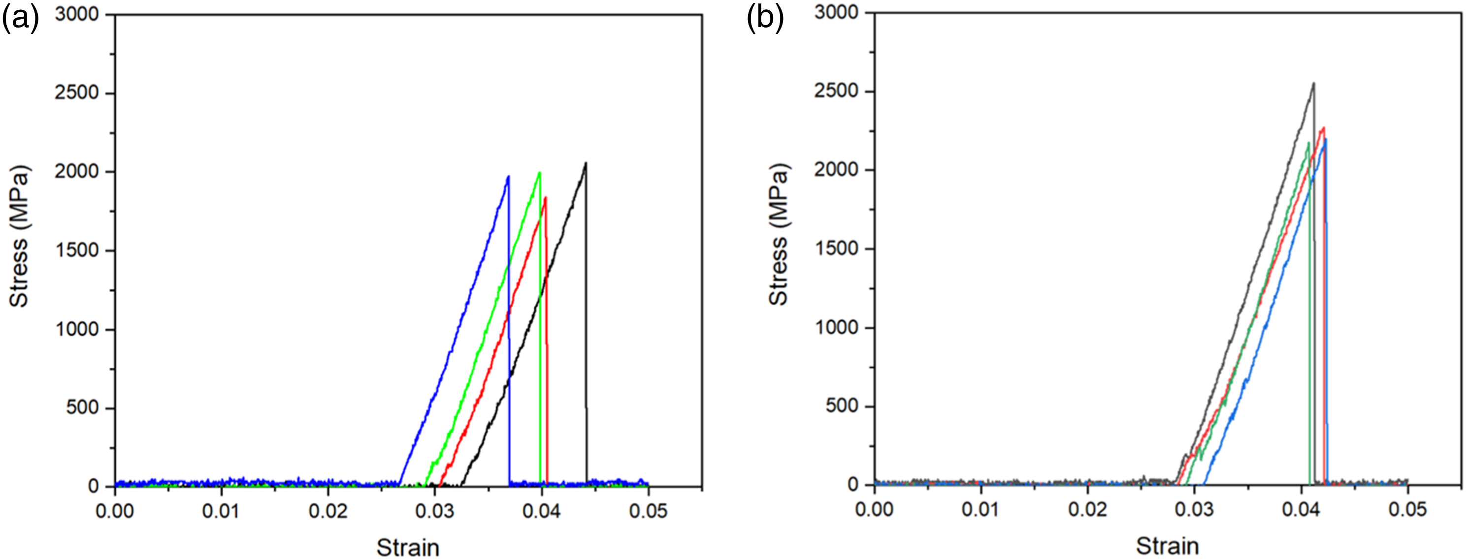
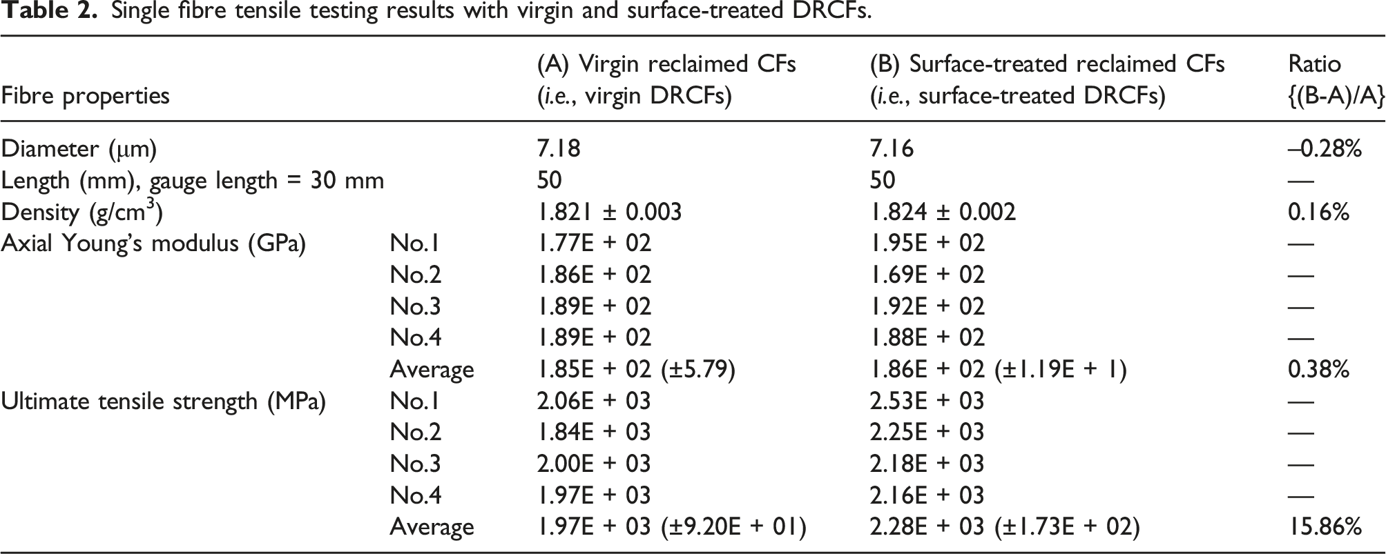
The density of DRCFs was measured using the pycnometer method with distilled water as the immersion liquid, following ASTM D2320-98(2003). The density was calculated using the following relation
21
:
In Table 2, the fibre density after surface treatment showed a small increment. The reason is that the mild alkali treatment of DRCFs etched the surface of the fibre leading to increased surface roughness and reduced diameter after treatment. In addition, this alkali solution led to the dissolution of amorphous fibre components, altering the chemical composition and causing a denser packing structure. As such, a layer of the mild alkali was deposited, resulting in an increase in both density and tensile strength of the single DRCF after surface treatment.
As a result of the surface treatment, reclaimed carbon fibres are less prone to undergo fibre flocculation in a fluid medium and transfer more load to the polymer matrix when remanufactured to composite product than using the virgin type of reclaimed fibres.
Computational fibre model and dispersion
Eulerian and Lagrangian methods are commonly used numerical methods in fluid dynamics. Fluid flow simulations based on the Eulerian approach generally employ a mesh-based technique, that is, the discretisation of space into regular grids or meshes for simulation. This mesh-based Eulerian method has certain limitations when modelling complicated fluid phenomena involving large motions. Mesh-free methods in comparison offer great flexibility in terms of boundary motion, including for cases where there is a rigid body motion. Common approaches for the mesh-free method are Smoothed Particle Hydrodynamics (SPH22–24) and Moving Particle Semi-implicit simulation (MPS17,18). The SPH method is mainly applied to the weakly compressible form in fluid dynamics, whereas the MPS method is well adapted for incompressible fluid flows involving an explicit calculation of the external force and an implicit calculation of the pressure.25–28
In this study, the MPS method based on Lagrangian approach is considered using the semi-implicit algorithm of a simplified marker and cell method which is widely used in incompressible fluid flow. Here, in practice, water (incompressible fluid flow) is used as a suitable phase for fibre dispersion since the water pressure changes involved are too small to make an appreciable change to the density. Pressure gradients between inter-fibre particles act as a repulsive force, which prevents close approach of the particles and facilitates dispersion. As part of a multi-phase flow involving solid and liquid phases, physical quantities pertain to each of the phases at position and velocity. For fibre dispersion in fluid flow, the fibre model is expressed as a set of particles of the bead-chain formation.29,30 The fibre movement in the fluid is characterised as exhibiting extension, bending and torsion, whereas the fluid model is assumed as extension and bending; fibre and fluid phases are derived from Stokes flow. 30
Fibre orientation is determined by several parameters such as fibre aspect ratio (length to diameter), fibre density (fibre concentration) and shear fluid flow. The fibre orientation can be influenced by fluid-mediated interactions between fibre-to-fluid and fibre-to-fibre contacts. Shear fluid flow is assumed in which fluid-mediated interactions with fibres occur continuously when the fibre concentration is set. The fibre orientation in relation to the fibre concentration influences the fibre dispersion along the fluid flow. At lower fibre concentrations, that is, when the extent of fibre orientational distribution is large, fibre flocculation rarely arises since the lower fibre concentration causes fewer fibre-fibre interactive contacts, so that fibre flocculation rarely arises.
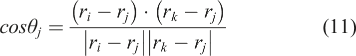
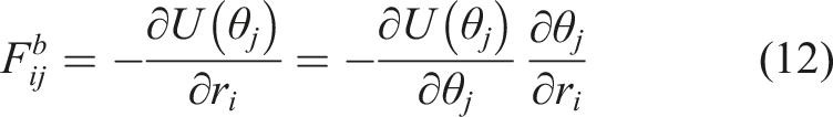
In this study, the fibre model based on the MPS method is developed by stretching and bending forces in 2-dimensional space. A stretching force is to maintain the distance between the fibre particles, and a bending force is to set an angle between the neighbouring fibres. The stretching force on a fibre is expressed as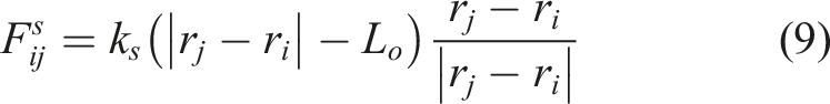
The bending force applied to a particle is shown in Figure 9. A pair of fibre particles used to build a fibre model.
The computational fibre model is executed using PETSc (Portable, Extensible Toolkit for Scientific Computation) libraries for partial differential equations and sparse matrix computations. 31 Thus, the incomplete Cholesky conjugate gradient (ICCG) method and the message passing interface (MPI) for pressure calculation are used in PETSc library. For boundary conditions, two layers of ghost (or so-called dummy) particles are used to avoid density deficiency near the boundary, and the velocity of the solid inner wall particles are set to zero so that fluid particles can flow without interference of the wall.
The fibre dispersion analysis with different fibre concentrations is shown in Figure 10. As time flows, fibre movement becomes more vigorous. Fibre orientation is changed along the shearing fluid flow in which the higher fibre density comes to yield a lower degree of orientational fibres. This is attributed to the higher fibre volume occupied in a fluid space, so the fluid resistance to fibre orientation relatively increases. This can be also applied to the longer fibres due to the larger fibre volume fraction occupied. Besides, the increase in fibre-to-fibre contacts cause fibre aggregation as shown in Figure 10. When the fibre bending ratio to stretching is high, the whirling of fibres occurs more as shown in Figure 10(c) and (f). At the higher fibre concentration, when the fibre-to-fluid contacts are achieved more, fibre accumulation is clearly observed. Fibre dispersion varied by fibre concentration and stiffness ratio.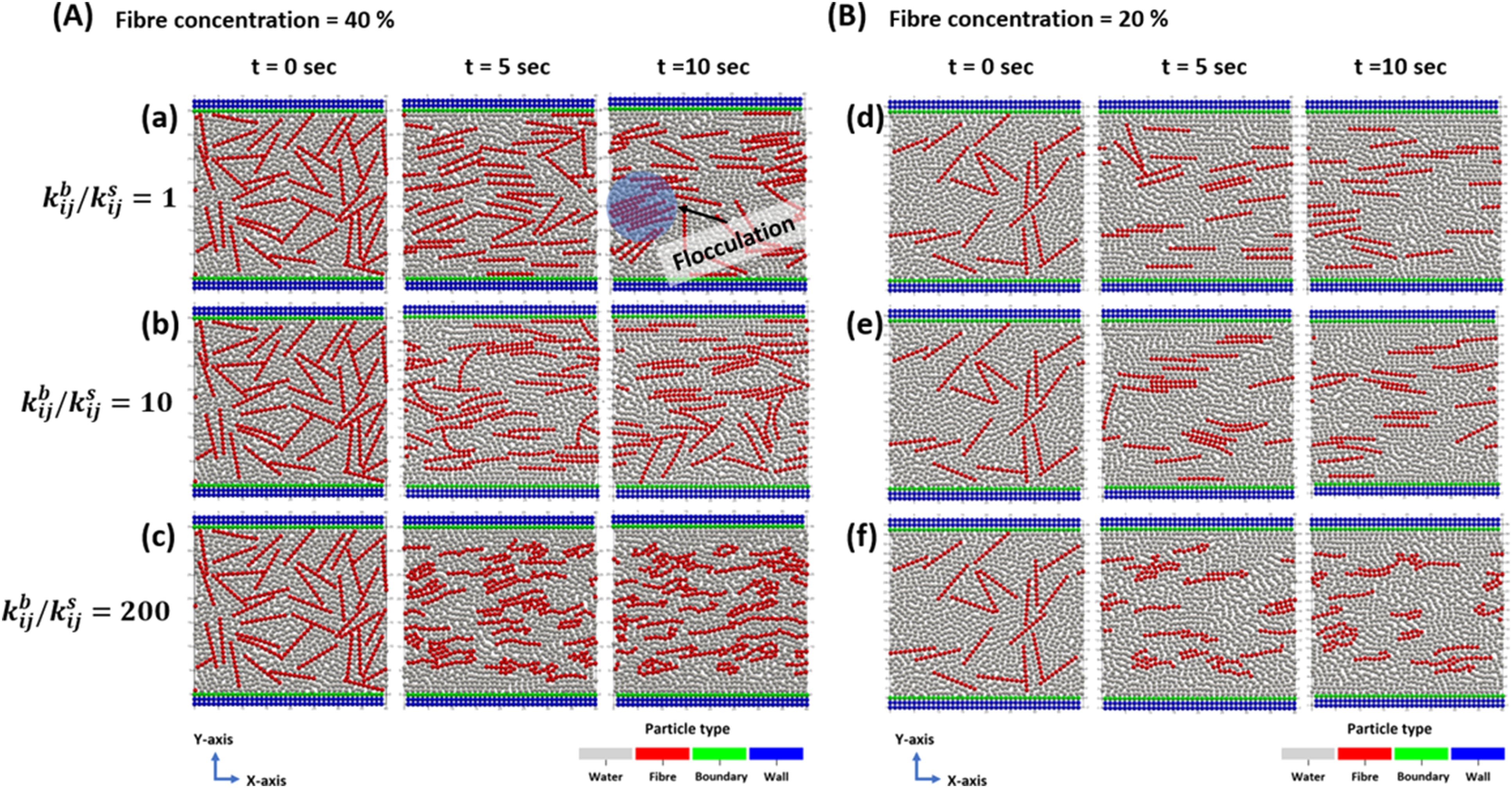
In Figure 11, the fibre bending angle is traced with respect to time for each case of Figure 10. The fibre bending effect is characterised according to the fibre concentration. Also, the fibre bending effect can respond to the fibre stiffness in that the higher fibre bending indicates the lower fibre stiffness. At the higher fibre stiffness index ( Fibre bending effect corresponding to Figure 10; (a)–(c) indicating to Figure 10(A) and (d)–(f) indicating to Figure 10(B).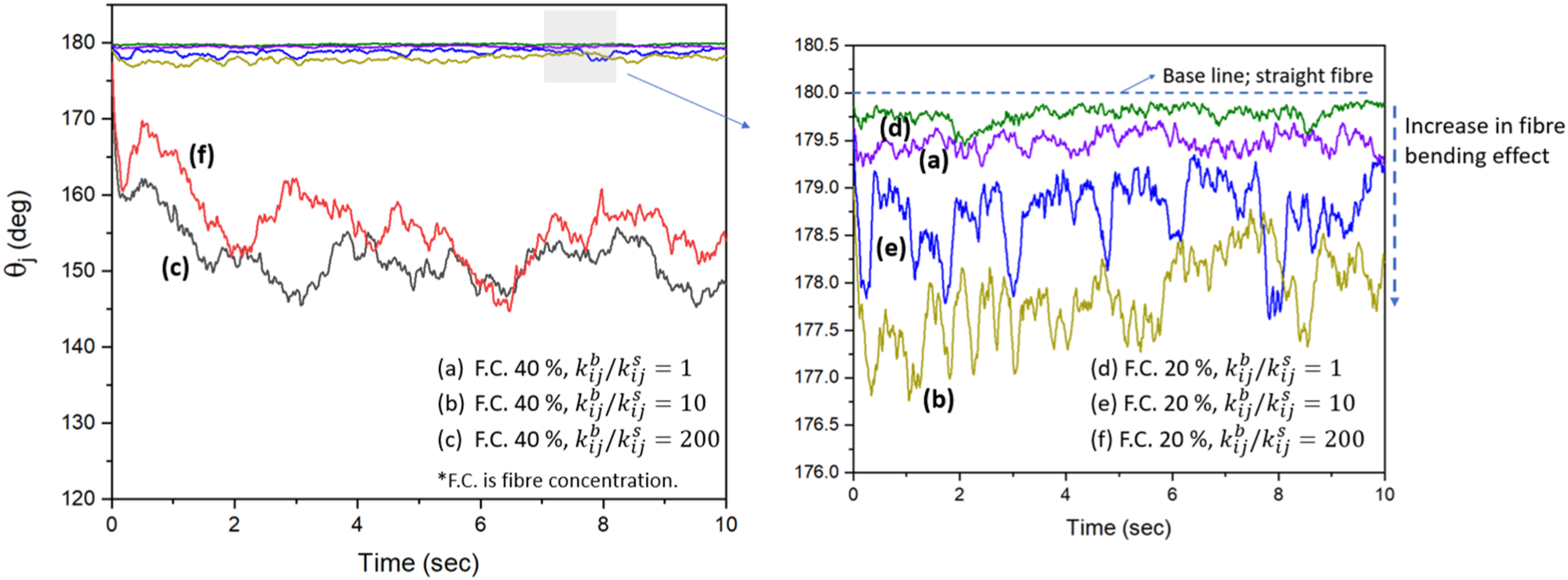
Fibre dispersion through physical methods
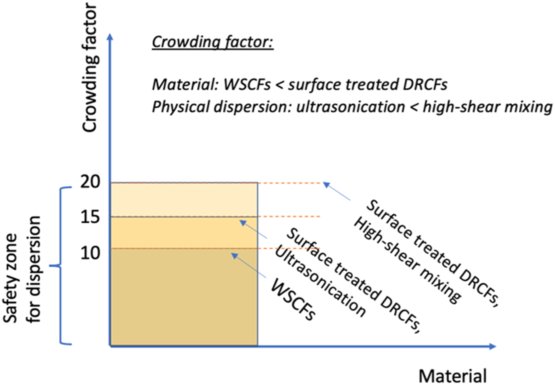
Fibre flocculation, that is, the formation of fibre entanglement by inter-fibre collisions, is a critical issue in the achievement of a stable fibre dispersion. The phenomenon of the inter-fibre collision is mainly attributed to the long fibres, fibre concentration (or fibre volume fraction) and the fibre thickness. The effect of fibre flocculation can be inversely interpreted by how uniformly the fibres are dispersed in water. The crowding factor is widely used for the fibre dispersion and as indication of fibre flocculation to predict a degree of the fibre flocs.
32
The crowding factor 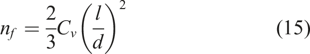
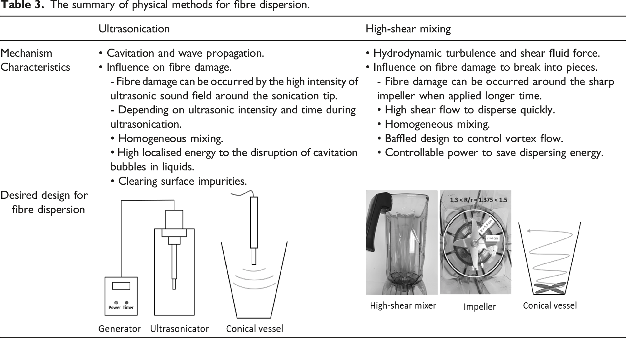
Fibre surface treatment contributes to a reduction in the number of fibre-fibre contacts and an increase in the number of interactions between the functional active sites on the fibres and water molecules. To investigate fibre dispersion before and after surface treatment, physical methods were used, that is, ultrasonication and high-shear mixing to break the initial fibre clumps and create high-shear fluid flow to overcome the fibre flocculation. Ultrasonication has been widely used and reported in many applications for the dispersion of strong agglomerates such as nanoparticles, because it can provide high energy to break interparticle bonds of the agglomerates.33–35 However, it has adverse effects on the surface damage of dispersive media when high power and long-lasting ultrasonication time are applied. Thus, a mixing system including a vessel size and a probe position in ultrasonication is important when attempting to achieve a homogeneous dispersion. 33 On the other hand, high-shear mixing can be used to quickly suspend more fibres due to the highly intensive shear force available to overcome fibre flocs due to the turbulent flow. However, the design of the vessel, baffles, and the number and shape of the mixing blades are critical to achieve the desired level of dispersion.36,37
The practical fibre dispersion was experimentally observed as shown in Figure 12; the vertical axis indicates the fibre dispersion in an arbitrary unit. Fibre dispersion per unit volume with respect to crowding factor implies how much fibre suspension was achieved per unit volume by observing a 3-dimensional volume vessel. It is obvious that the fibre dispersion is clearly influenced by the crowding factor. Polar-hydrophilic fibres obtained from surface treatment have large functional active sites to interact water molecules, thereby the less fibre flocculation is shown. Figure 13 shows the effect of fibre dispersion depending on the physical dispersion methods. When setting a 6 mm fibre length for the prepared fibres, the surface-treated DRCFs have the highest crowding factor, followed by ultrasonication and WSCFs. As for WSCFs, there was no such outstanding dispersion effect even using ultrasonication and high-shear mixing methods. This is because non-polar hydrophobic fibres are suspended after coated binding agents on the fibres are dissolved in water, and prone to fibre flocs. This is the limitation to the non-polar hydrophobic fibres in terms of fibre dispersion, which is unlike to the surface-treated DRCFs. The surface-treated DRCFs are acting as polar-hydrophilic fibres, so water molecules of the working fluid are more active to react with them. Fibre dispersion per unit volume with respect to crowding factor. Fibre dispersion per unit volume with respect to crowding factor.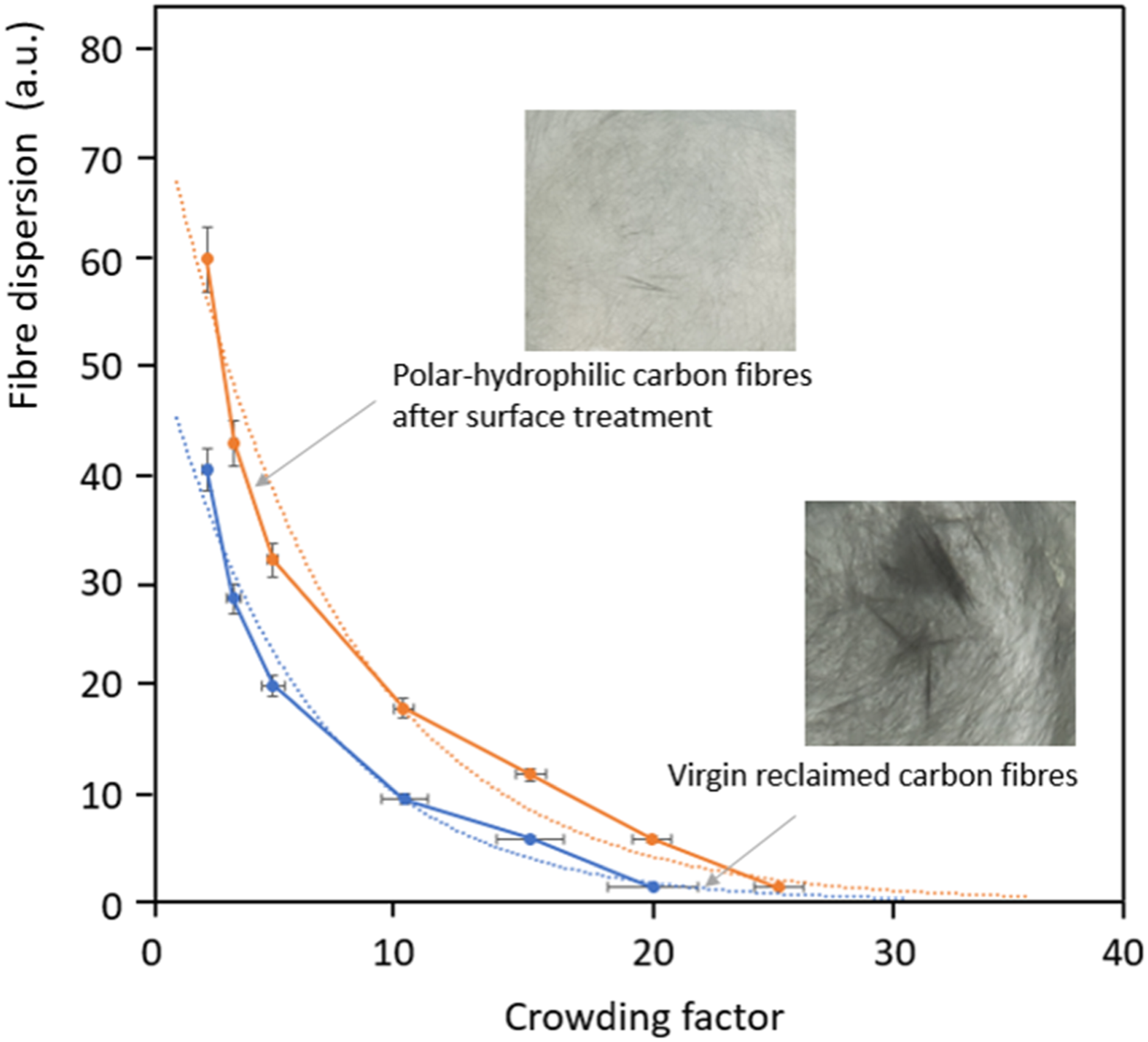
Comparison of physical dispersion methods
The summary of physical methods for fibre dispersion.
Compared to ultrasonication, high-shear mixing is much preferred to achieve the high level of fibre dispersion with a relatively lower power and less time. The effect of baffles was investigated with the use of DRCFs. In Figure 14(a), without baffles, fibre initial clumps and flocs remained to the virgin DRCFs. However, the surface-treated DRCFs produce a stable dispersion. In Figure 14(b), fibre dispersion is shown with respect to time for the simple baffled design of the vessel. The homogeneous fibre dispersion was observed to the surface-treated DRCFs as the baffles obstruct turbulent eddies and contribute to a more homogenous suspension flow. Baffle effect for achieving a stable fibre dispersion.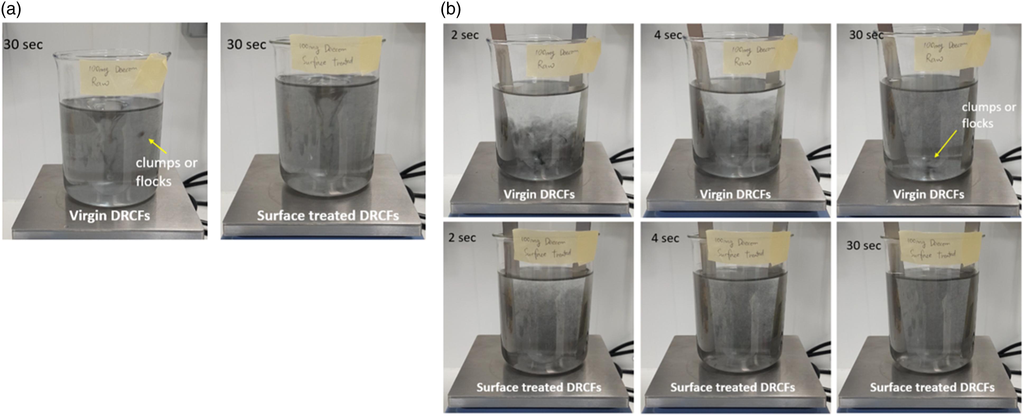
Consequently, the desired surface roughness and the functional groups on the fibres are important to control fibre suspension in a fluid medium with no flocculation. Most of the research literature relating to fibre flocculation cites the increasing fibre stiffness as one of the parameters to cause fibre flocs; however, polar-hydrophilic fibres even with the increased stiffness do not present adverse effects on the fibre dispersion in this study, which is interesting in our findings. Thus, the increased fibre stiffness induced by the surface treatment can contribute to the interfacial bonding with polymer resins to yield the improving mechanical properties of FRP composites.
Conclusion
The desired surface roughness and the surface functional groups on the reclaimed fibres are critical parameters to effect on the fibre suspension in a fluid medium to avoid fibre flocculation. In this study, the surface treatment of virgin discontinuous reclaimed carbon fibres yields C–H stretching and bending modes and O–H bending and vibration modes, and the increase of hydroxyl functional groups on the fibres acts as polar-hydrophilic performance, which is favourable for the interactions with water molecules. After surface treatment of the reclaimed carbon fibres, fibre dispersion increases higher than the proprietary water-soluble carbon fibres used for comparison (N.B., the water-soluble carbon fibres are not literally soluble, but the term refers to a proprietary water-soluble sizing that is applied). The mild alkali surface treatment on the reclaimed carbon fibres yields improving mechanical properties (15.86% increase in the ultimate tensile strength and 0.38% increase in the axial Young’s modulus).
Hydrodynamic simulation with a fibre model was carried out using a moving particle semi-implicit method. Fibre stiffness index (
With the increase in crowding factor used to characterise fibre dispersion effect in water suspension, the fibre surface treatment contributes to the decrease in bridging fibre-fibre contacts and the relative increase in affinity to the water molecules, and thereby the level of fibre dispersion reaches high. Physical dispersion methods including ultrasonication and high-shear mixing were compared, and consequently, the high-shear mixing method was shown for the better fibre dispersion due to the hydrodynamic turbulence and shear fluid force. A baffled vessel yielded the formation of a stable fibre dispersion for the surface-treated reclaimed fibres; this is due to the reason that the baffles obstruct hydrodynamic turbulent eddies and contribute the more homogenous suspension flow.
Footnotes
Declaration of conflicting interests
The author(s) declared no potential conflicts of interest with respect to the research, authorship, and/or publication of this article.
Funding
The author(s) disclosed receipt of the following financial support for the research, authorship, and/or publication of this article: This work was supported by the Engineering and Physical Sciences Research Council (EPSRC) through grant EP/P027393/1 (High Performance Discontinuous Fibre Composites - a sustainable route to the next generation of composites) and the EPSRC Centre for Doctoral Training in Advanced Composites for Innovation and Science (EP/L016028/1) (DB) University of Bristol.