
Abstract
Tidal turbine infrastructure is currently in the large-scale prototype and short-term demonstration phase. However, the immediate requirement is to develop materials, processes and long-term life predictive facilities for tidal turbine plant that has decades of operational lifetime requirements. Computational modelling is a key tool to interpret the experimental data, understand the relevant mechanisms and provide a predictive capability for the performance of aged components for industries. The goal of this paper is a prediction of the long-term life of marine-based glass/epoxy and carbon/epoxy composite laminates aged in artificial seawater with 3.5% salinity based on Arrhenius degradation theory and tensile strength retention over 180 days ageing at room temperature and 60°C. Three different analytical models (linear and exponential) were implemented to calculate time shift factors and corresponding life in a real marine environment. Additionally, multi-scale modelling has been implemented via a representative volume element approach for square and hexagonal cells, and two-step homogenization of textile composites in accordance with nanoindentation testing for matrix/resin cells and fibre constraint cells after 90 days of immersion in saltwater. In general, the multi-scale modelling in ABAQUS and TexGen4SC was able to approximate (with about 10% difference) the mechanical properties of dry and aged composite laminates.
Introduction
The term ‘lifetime of a product’ defines the time frame over which minimal degradation is expected to occur and is a primary consideration for customers acquiring composite based products and consequently it is of primary importance to composite product manufacturers. The challenge is to understand, predict and minimise the long-term degradation mechanisms of a composite material in its environment. This knowledge is required for accurate predictions of product lifetimes and warranties. In addition, understanding degradation mechanisms will ultimately lead to increased product lifetimes, longer product warranties and increased customer options and experiences through new materials, coatings and processes. Understanding the ageing process often requires an accelerated testing program that induces progressive damage or delamination leading directly to failure or loss in service performance. Therefore, it is essential to make a connection between the laboratory ageing process (accelerated testing time) and service environment (i.e. seawater) exposure time (long-term life). Accelerated exposures are used to produce end-of-life micro-structure or damage states for subsequent characterization tests. The required life cycle for marine-based structures (10–20 years) means that accelerated ageing tests in suitable hydrothermal environments provide a more cost-effective strategy than real-time testing to evaluate material performance. There is a wide variety of literature that explores the ageing of composites in marine environments.1,2,3,4 Most use immersion in water at elevated temperatures for varying lengths of time, and rely on time-temperature superposition principle to extrapolate long-term exposure properties. Kant and Penumadu 5 showed that the fibres soaked with seawater did not show a clear trend of variation in measured properties such as failure stress and modulus variation with strain as a function of exposure conditions. Santos Souza et al. 6 explored an effective decrease in properties of elasticity and tensile resistance by the composite, directly proportionally to the ageing time. It’s possible to conclude that salt water absorption degrades both fibre and resin. Ghabezi and Harrison 3 investigated the long-term performance of carbon/epoxy and glass/epoxy laminates in an artificial seawater environment. Accelerated ageing tests were conducted at 60°C for 45 days to characterise the long-term effect of seawater on the mechanical response of fibre reinforced composite laminates. Öndürücü et al. 7 observed that the critical buckling loads of the samples immersed in seawater decreased when compared to the critical buckling loads of the samples kept at room temperature. Ray 8 has examined the effects of changing seawater temperature on the mechanical properties of GRP composites. Glass fibers were exposed to two seawater bath and then subjected to two thermal shocks (higher and lower side). The numerical results showed that it was possible to relate the experimental results to the linear or elastic portion of the plots. Li 9 has assessed the effect of temperature and moisture effects on composite materials for wind turbine blades with E-glass fibers and different matrices (vinyl esters and epoxy). Pan and Zhong 10 have developed a micromechanical model to study the mechanical degradation of natural fibre reinforced composites induced by moisture absorption. The results from theoretical prediction for the randomly oriented straight fibre reinforced composite were compared with experimental results from literature. Deroin et al. 11 revealed the presence of only one irreversible degradation mechanism, that is, hydrolytic degradation, which is temperature dependant. So, within the approach assumptions, the lifetime in distilled water of poly (3-hydroxybutyrate-co-3-hydroxyvalerate) following Arrhenius behaviour can be predicted. The long-term behaviour of basalt- and glass-fibre reinforced polymer bars under the seawater and sea sand concrete environment was predicted by Wang et al. 12 using Arrhenius degradation theory. Udhayaraman and Mulay 13 have studied the micromechanical constitutive modelling of unidirectional fibre reinforced and plain woven textile composites. Computational homogenisation of representative volume element (RVE) of transverse direction unidirectional composite was performed satisfying the periodicity of RVE. Liu et al. 14 developed an RVE model with embedded solid elements to predict the effective elastic constants of discontinuous fibre reinforced composites.
In this novel study, firstly, long-term life of glass/epoxy composite made by hand lay-up and procured carbon/epoxy composite laminates are aged in artificial seawater are assessed through a range of experimental-analytical models based on Arrhenius degradation theory and tensile strength retention following 6 months ageing in salt water at room temperature and elevated temperature. Secondly, multi-scale modelling of the aged samples was implemented via RVE approach in ABAQUS and TexGen4SC software based on nanoindentation test results after 90 days of immersion in saltwater for two different material configuration cells.
Materials and preparation
Six layers of Biaxial glass reinforcement with ±45° fibre orientation and surface density 320 gr/m2 suitable for use in a wide range of glass reinforced composite applications was used as reinforcing in EL2 epoxy AT30 FAST laminating resin (Easy Composites Ltd, Staffordshire, UK, product code: EP-L2-F-05, tensile strength 70 MPa and 7% elongation at break 15) made by hand lay-up method. Easycomposites’ (Staffordshire, UK) high strength carbon fibre sheet (CFS-RI-2-1900, 2 mm × 2000 mm × 950 mm) was manufactured using 100% carbon fibre reinforcement and epoxy resin matrix, 15 cured under pressure at elevated temperature to produce a carbon fibre sheet with engineering-grade mechanical properties and a class-A surface finish. To create a more uniform distribution of strength, the sheets are manufactured using both layers of 0°/90° and 45°/−45° oriented reinforcement with 2 mm thickness in what is known as quasi-isotropic fibre orientation. In this research, to make seawater with 3.5% salinity (the average ocean surface salinity 16 ) in a laboratory, 35 g of salt was added to a beaker, and then added tap water until the total mass was 1000 g, stirring until the salt was completely dissolved in the water. For the ageing process of composite laminates at room temperature and 60°C for 6 months, water-heating WiseCircu baths (EDHWCB-11 and EDHWCB-22, Seoul, South Korea) with a circulating pump continuously used.
Tensile test
The mechanical properties of dry and aged glass/epoxy and carbon/epoxy laminates (the average value of five tested samples) were conducted using a hydraulic Instron 8800 tensile test machine according to ASTM D3039.
17
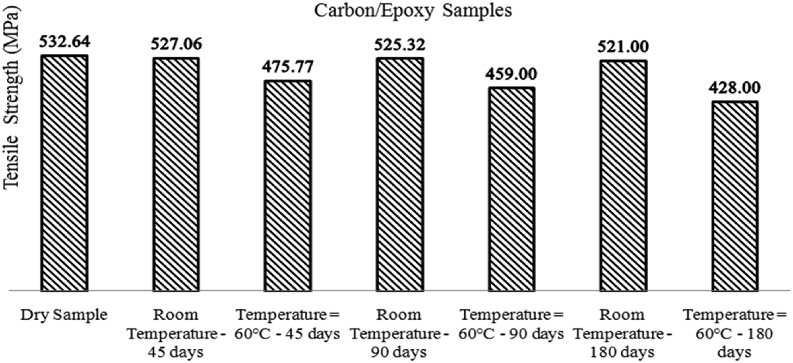
The tensile strength in glass/epoxy was determined as a mean value of 106.33 ± 1.7 MPa for the dry (reference) specimen (Figure 1). The tensile strength of glass/epoxy at room temperature after 45 (105.03 ± 2 MPa), 90 (104.4 ± 2 MPa) and 180 (102.24 ± 2 MPa) days were measured. The elevated temperature has affected the tensile strength significantly. Mean tensile strength at 60°C after 45 days immersion in salt water was 83.66 ± 2 MPa. Continuing the water immersion in the artificial salt water showed more reduction in the tensile strength of glass/epoxy specimens as 79 ± 1.8 MPa after 90 days, whereas this value decreased to 77.77 ± 1.5 MPa after 180 days. In the same way, the tensile strength of carbon/epoxy was determined, obtaining a mean value of 532.64 ± 2 MPa for dry carbon/epoxy specimens (Figure 2). The tensile strength was 475.77 ± 2.1 MPa for aged carbon/epoxy specimens at 60°C, after 45 days. The effect of seawater on tensile strength after 90 days (459 ± 2.5 MPa) and 180 (428 ± 2 MPa) days at elevated temperature was significant. Tensile test results of dry and aged composite glass/epoxy samples. Tensile test results of dry and aged composite carbon/epoxy samples.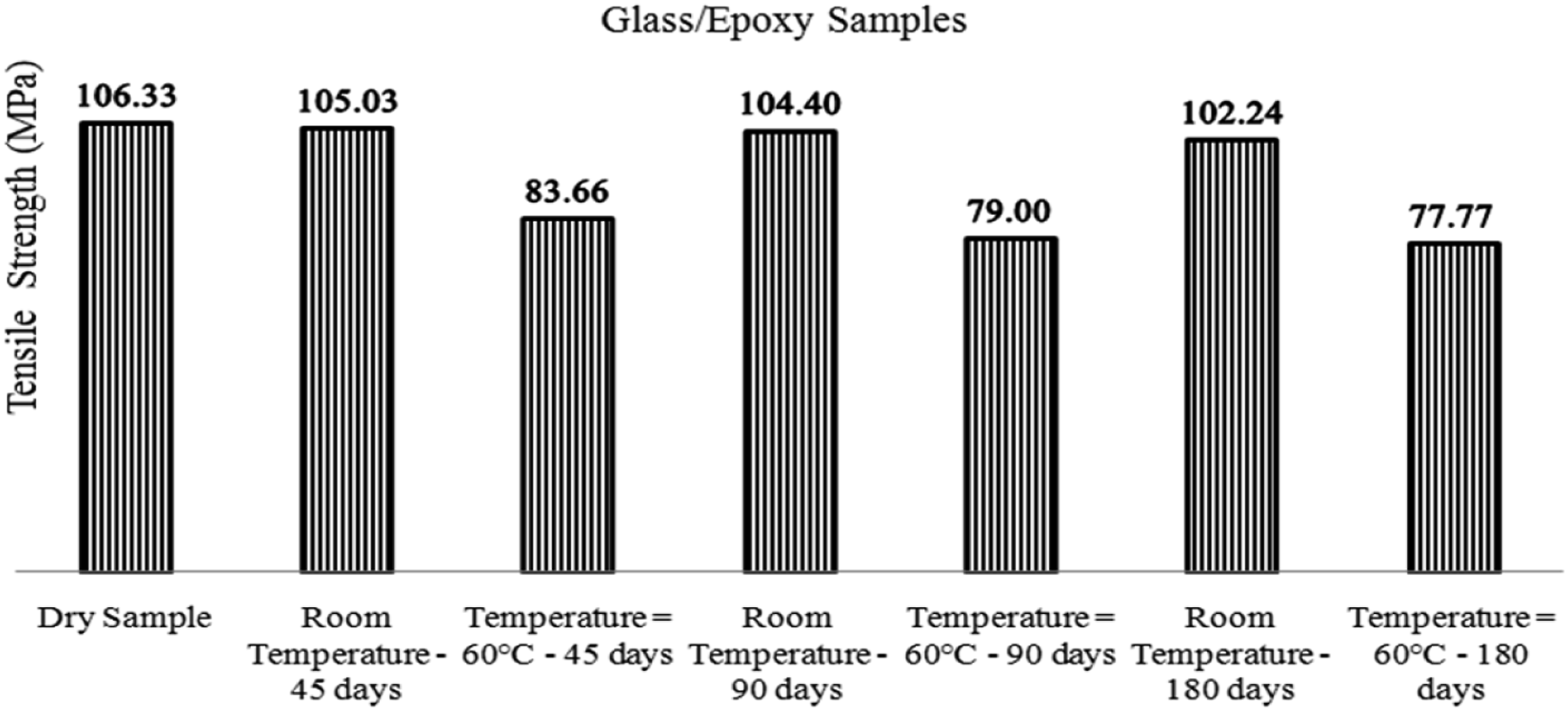
Nanoindentation testing of composite materials
The nanoindentation technique was carried out using a Keysight Nanoindenter G200 (Compliance with ISO 14,577). The nanoindentation characterisation tests involve a Berkovich indentor have been carried out in compliance with a standard test method, which measures elastic modulus and hardness in maximum depth or load. Load is measured as a function of penetration depth in nanoindentation tests. The bulk properties of the fibre and matrix constituents are often used in fibrous composite micromechanical simulations to predict the composite properties and failure behaviour.18,19 Grinding and polishing procedure was carried out on the specimens using the Buehler AutoMet 250 machine in order to reduce the surface roughness less than 5%
18
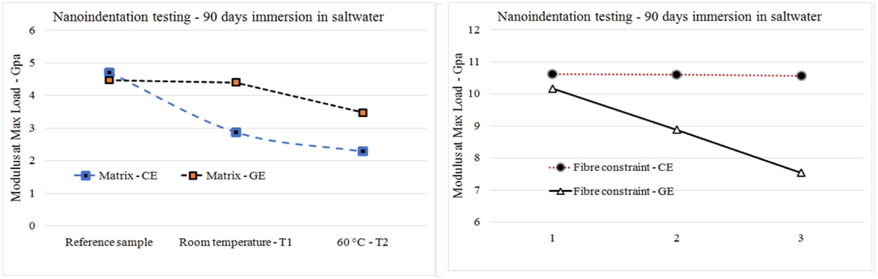
of the depth at which results are required. The modulus at the maximum penetration of a four load–unload indent cycle for both resin cell and fibre constraint cell as shown in Figure 3 were measured. Average modulus of matrix cells at maximum load in reference glass/epoxy specimens was 4.47 ± 0.5 GPa, which after 90 days of ageing in room temperature, there was just a very slight drop in modulus (4.4 ± 0.4 GPa) (Figure 4). It is apparent from Figure 4 that the average value of modulus in the aged glass/epoxy at 60°C was 3.47 ± 0.5 GPa, corresponding to a 22.3% degradation in these samples. It can be seen that the average value of modulus in the reference carbon/epoxy samples was 4.7 ± 0.3 GPa, while those values for aged samples at room temperature and 60°C were calculated as 2.875 ± 0.1 GPa (−38.8%) and 2.287 ± 0.1 GPa (−51.3%), respectively. The constraining effect of the surrounding fibres on the indentation modulus of composite specimens was characterised using nanoindentation technique. The tests were performed in parallel direction of fibres. The experimental data for modulus are presented in Figure 4. It is evident from the results for carbon/epoxy composite cells that there was no change in modulus indentation (10.6 ± 0.2 GPa) during ageing process at both temperatures. With regard to the indentation characterisation in glass/epoxy samples, 12.58% (8.89 ± 0.4 GPa) reduction in modulus was calculated at room temperature, and 25.8% (7.54 ± 0.5 GPa) at 60°C with respect to the reference specimen (10.17 ± 0.5 GPa). In situ resin/matrix and fibre constraint cells. Nanoindentation results for matrix cells (CE = carbon/epoxy, and GE = glass/epoxy).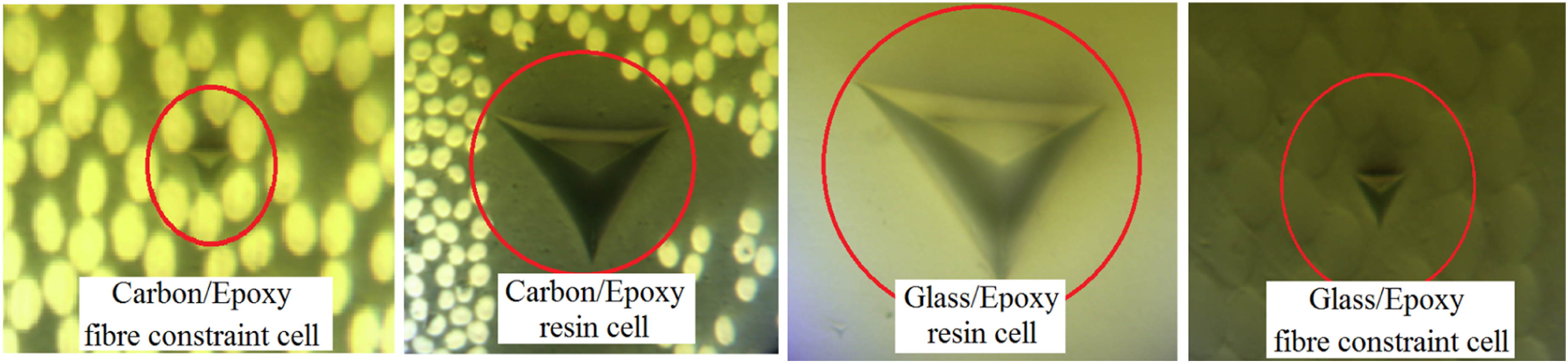
The main physical degradation mechanisms of the polymer resins are mechanical-based damage such as plasticisation and swelling, which may cause softening in the polymer/composite, reducing its mechanical properties such as tensile strength, flexural properties and micro-scale properties from nanoindentation as shown above. Water penetration can also result in hydrolysis of epoxy resin and deteoriation of the fibre/matrix interface. In addition, chemical-based mechanisms lead to changes to the polymer matrix that are not reversible and occur primarily due to hydrolytic deterioration, whereby the diffusion of water into the composite causes chain scission. 20
Theoretical prediction of long-term behaviour of composite samples
Linear model
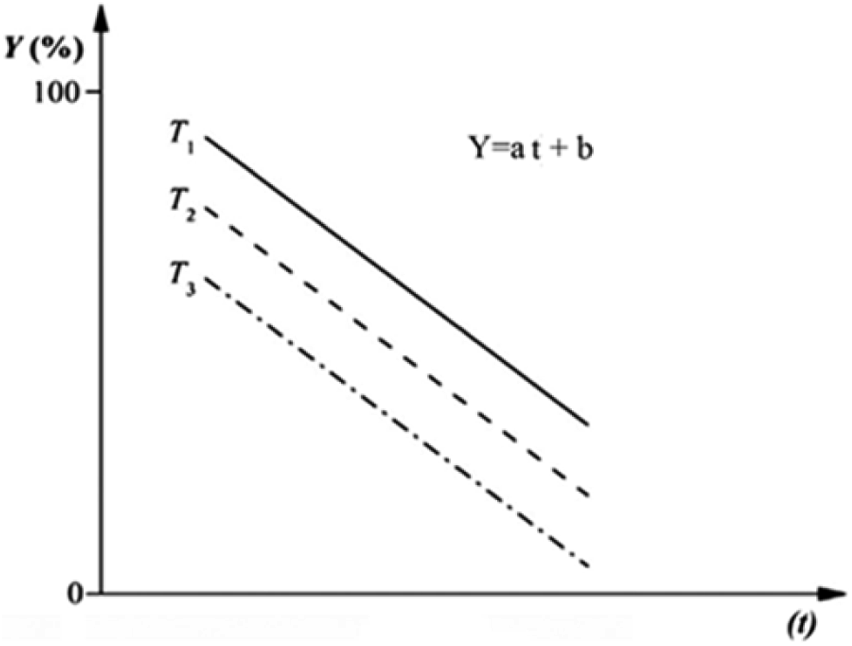
To evaluate the long-term performance of glass/epoxy and carbon/epoxy composite samples in its environment, the Arrhenius relation was adopted by researchers based on the short-term data from accelerated ageing tests. The basic assumption of Arrhenius relation is that the single dominant degradation mechanism of the material does not change with time and temperature during the exposure, whereas the rate of degradation is accelerated with the increase in temperature.12 There are different theoretical models to predict long-term life of composite aged specimens in compliance with Arrhenius law. Linear model
21
(Figure 5) has been successfully used to predict the long-term tensile strength of composite bars, in spite of some limitations of this model.
22
This model is only a phenomenological representation of test data and never provides any hypothesis of the degradation mechanism (Y represents the tensile strength retention (%), and t represents the exposure time). On the other hand, according to this model, the residual strength reaches minus values at long ageing time (crosses time axis), which is obviously contradictory with the real test data. Schematic of linear model for life prediction of composite materials.
21
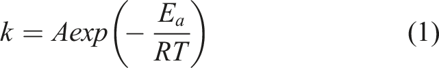
In the prediction models, the degradation rate can be expressed in the Arrhenius relationship by the following equation
12
The long-term behaviour of the composite samples under the service construction condition in the coast of Ireland was predicted using Arrhenius degradation theory in compliance with linear and non-linear models. First of all, on the basis of Figure 5(a), the fitted curve for glass/epoxy composite samples aged at room temperature and elevated temperature (60°C) after 45, 90 and 180 days was drawn and shown in Figure 6, and corresponding a and b coefficients were calculated. Second of all, The curve was drawn for ln (t) versus 1/T, and time to reach 90%, 80%, 70% and 60% tensile strength retention, which the straight lines were exactly parallel (the same slope). The slope of the straight lines which is corresponding to E
a
/R was measured as 5670 (J/mol)/(J K−1mol−1) (Figure 7). Tensile strength retention for glass/epoxy samples versus days. Logarithmic of time to reach different levels of tensile strength retention Vs 1/T (1/K).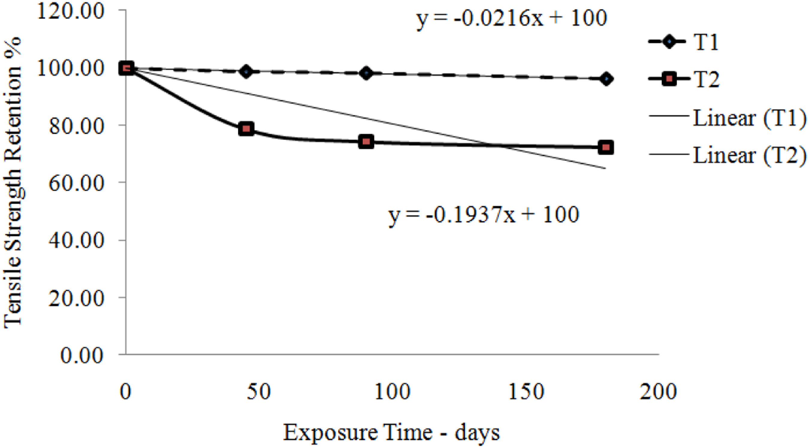
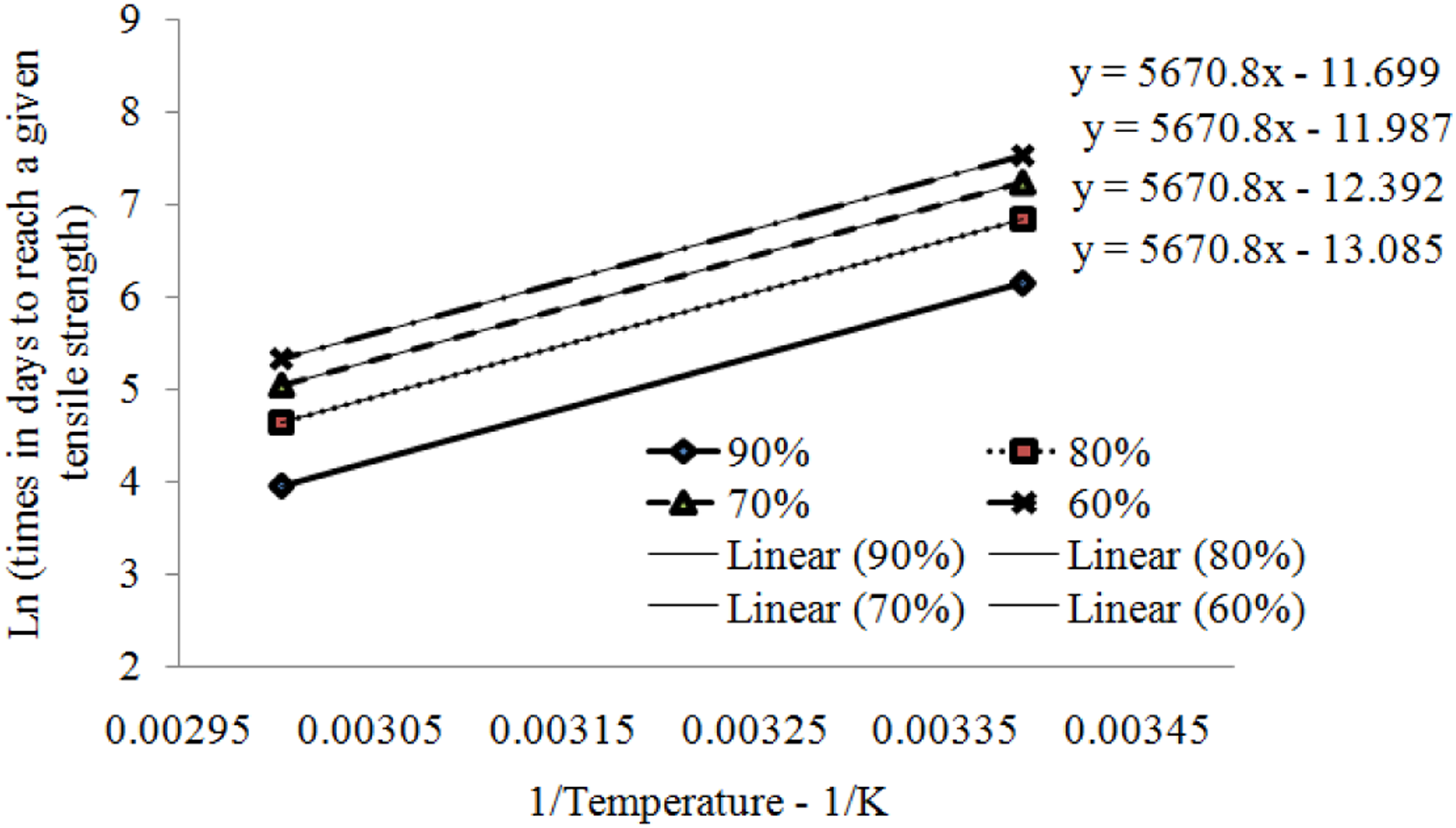
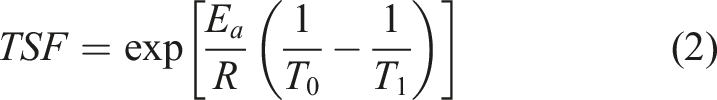
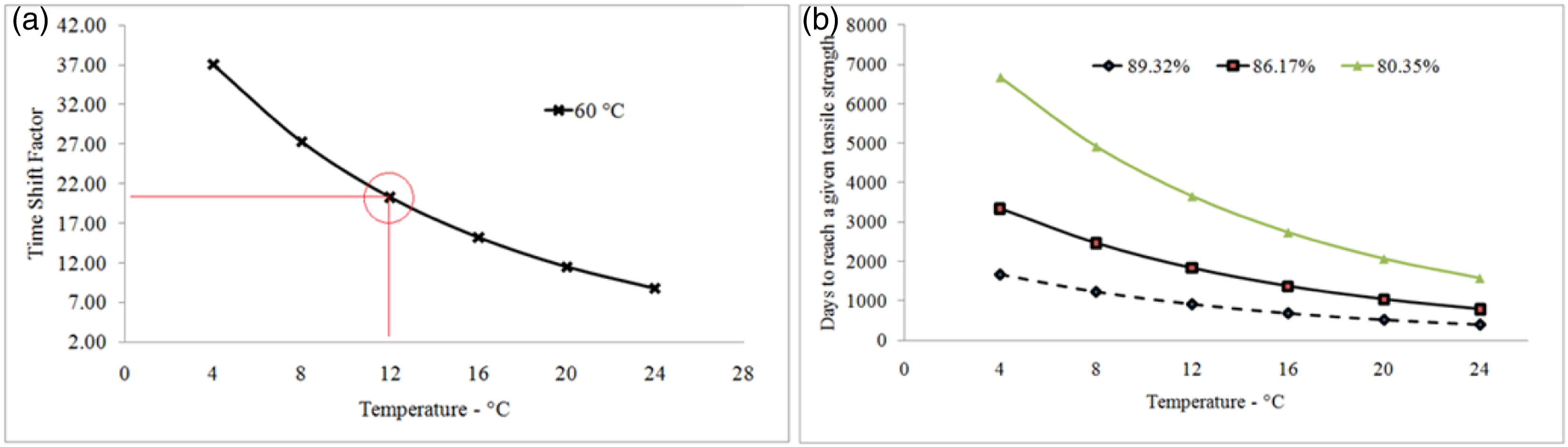
Figure 8a indicates the variation of time shift factor or acceleration factor for glass/epoxy composite samples for a range of reference temperatures and an ageing temperature of 60°C. This information is useful in linking the accelerated ageing test results in this work to the actual ageing experienced by real applications such as turbine blade materials over the expected operational life of a tidal energy device
23
immersed in water temperatures between 4°C and 24°C. Based on a reference temperature of 12°C, estimated as the operating temperature of a tidal turbine device off the coast of Ireland,
23
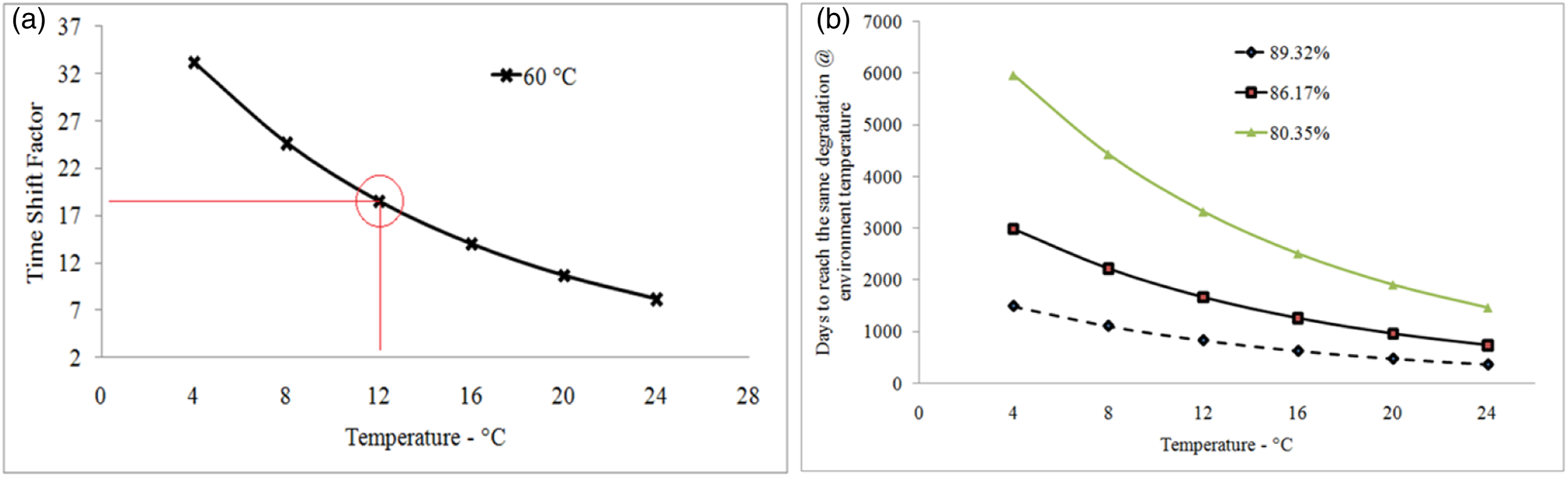
an acceleration factor of 17.6 was estimated for glass/epoxy tested in this research at 12°C (Figure 8a). In this work, accelerated ageing and tensile strength retention 78.67% during 45 days, 74.3% over 90 days and 72.42% after 180 days took place at 60°C, corresponding to an ageing period of 792, 1584 and 3167 days at 12°C, respectively (Figure 8b). In the same way, Figure 9a illustrates the variation of TSF for carbon/epoxy composite samples. Accelerated ageing and tensile strength retention 89.32% during 45 days, 86.17% over 90 days and 80.35% after 180 days took place at 60°C, corresponding to an ageing period of 831, 1662, and 3323 days at 12°C, respectively (Figure 9b). TSF versus reference temperature for glass/epoxy composites at 60°C (a), and Prediction of long-term life of glass/epoxy composite samples at 12°C (b). TSF versus reference temperature for carbon/epoxy composites at 60°C (a), and Prediction of long-term life of carbon/epoxy composite samples at 12°C (b).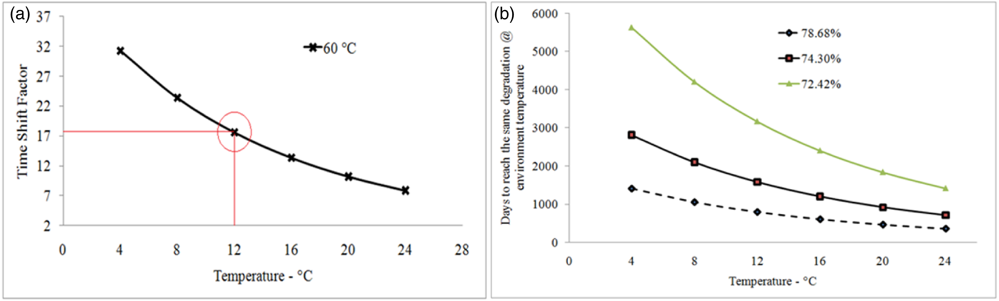
Non-linear models
Unlike linear model, non-linear models such as exponential models consider that the degradation rate of mechanical properties of aged composites is high in the initial stage, and then reduces with the increase of exposure time.
12
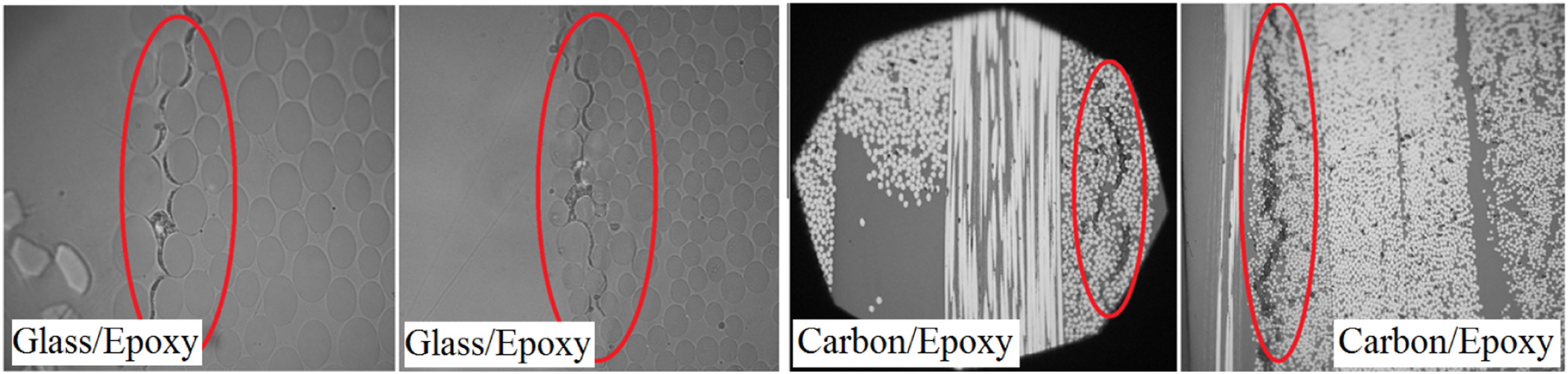
The degradation mechanism of composites for these models is assumed to be debonding at the fibre/matrix interface,24,25,26 which was also confirmed with the microscopic images in this research for ageing process on glass/epoxy and carbon/epoxy composites (Figure 10). The non-linear model presented in Figure 5b was used by some researchers,27,28 which suggested a service life prediction procedure for composite materials that the accelerated ageing data could be calculated and plotted with the property retention versus time. These exponential models are as follow (Figure 11)
12
Matrix cracking and fibre de-bounding in the aged composite specimens at 60°C. Exponential models (Model A and Model B) for life prediction of composite samples.
12
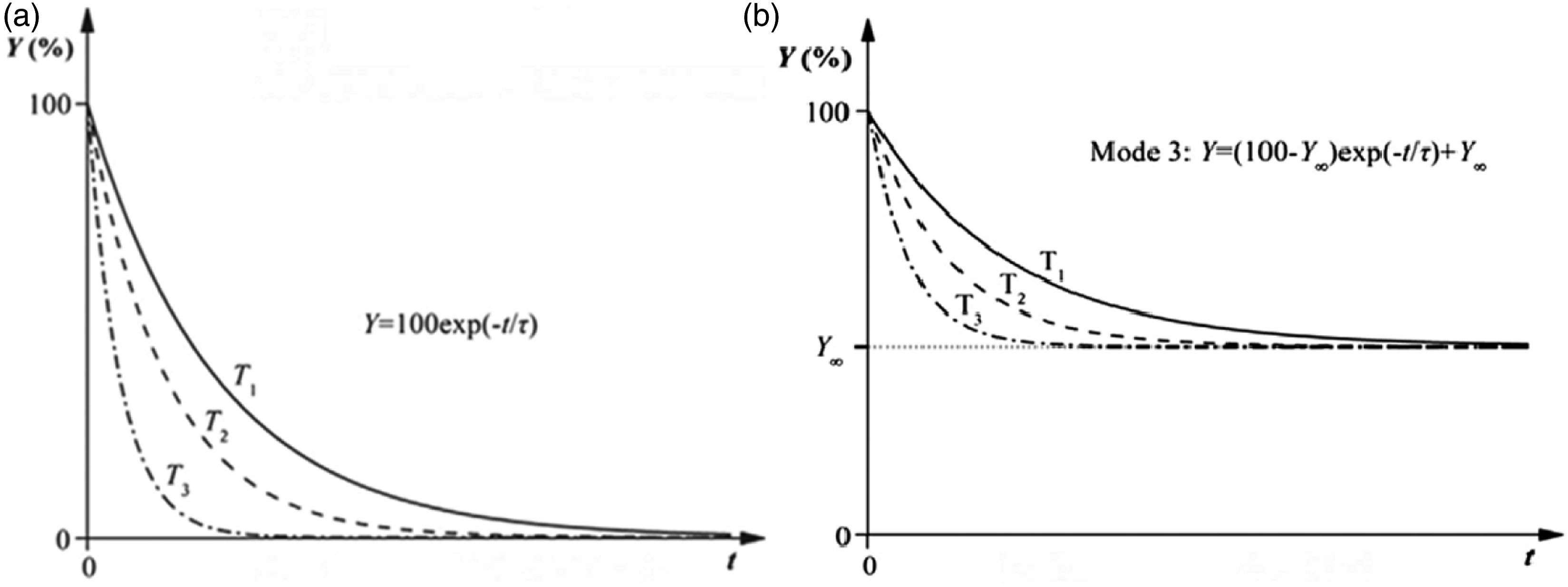
Long-term prediction of glass/epoxy and carbon/epoxy composite specimens at room temperature and 60°C over 6 months immersion in artificial seawater was calculated using accelerated test results with the exponential models in equation (3) as well as equation (4) with assumption of Y
∞
= 72% and 80% for glass/epoxy and carbon/epoxy, respectively. In order to calculate the more accurate value of Y∞, conducting the ageing process for longer time (more than 2 years) is necessary. The fitted curve for carbon/epoxy composite samples based on equation (3) aged at room temperature and elevated temperature (60°C) after 45, 90 and 180 days was drawn and shown in Figure 12, and corresponding τ coefficient was calculated. Then equation (3) was fitted to those values (ln t and 1/T), to reach 90%, 80%, 70% and 60% tensile strength retention, and the straight lines were exactly parallel (the same slope). The slope of the straight lines which is corresponding to E
a
/R was measured as 5952.5 (J/mol)/(JK−1mol−1). Figure 13 presents the variation of time shift factor or acceleration factor for glass/epoxy composite samples for a range of reference temperatures and an ageing temperature of 60°C. Based on a reference temperature of 12°C, estimated as the operating temperature of a tidal turbine device off the coast of Ireland
23
an acceleration factor of 20.3 was estimated for carbon/epoxy tested in this research at 12°C (Figure 13a). The accelerated ageing and tensile strength retention 89.32% during 45 days, 86.17% over 90 days and 80.35% after 180 days took place at 60°C, corresponding to an ageing period of 913, 1827 and 3654 days at 12°C, respectively (Figure 13b). Tensile strength retention for carbon/epoxy samples versus days (Model A). TSF versus reference temperature at 60°C (a), and prediction of long-term life of carbon/epoxy (Model A) (b).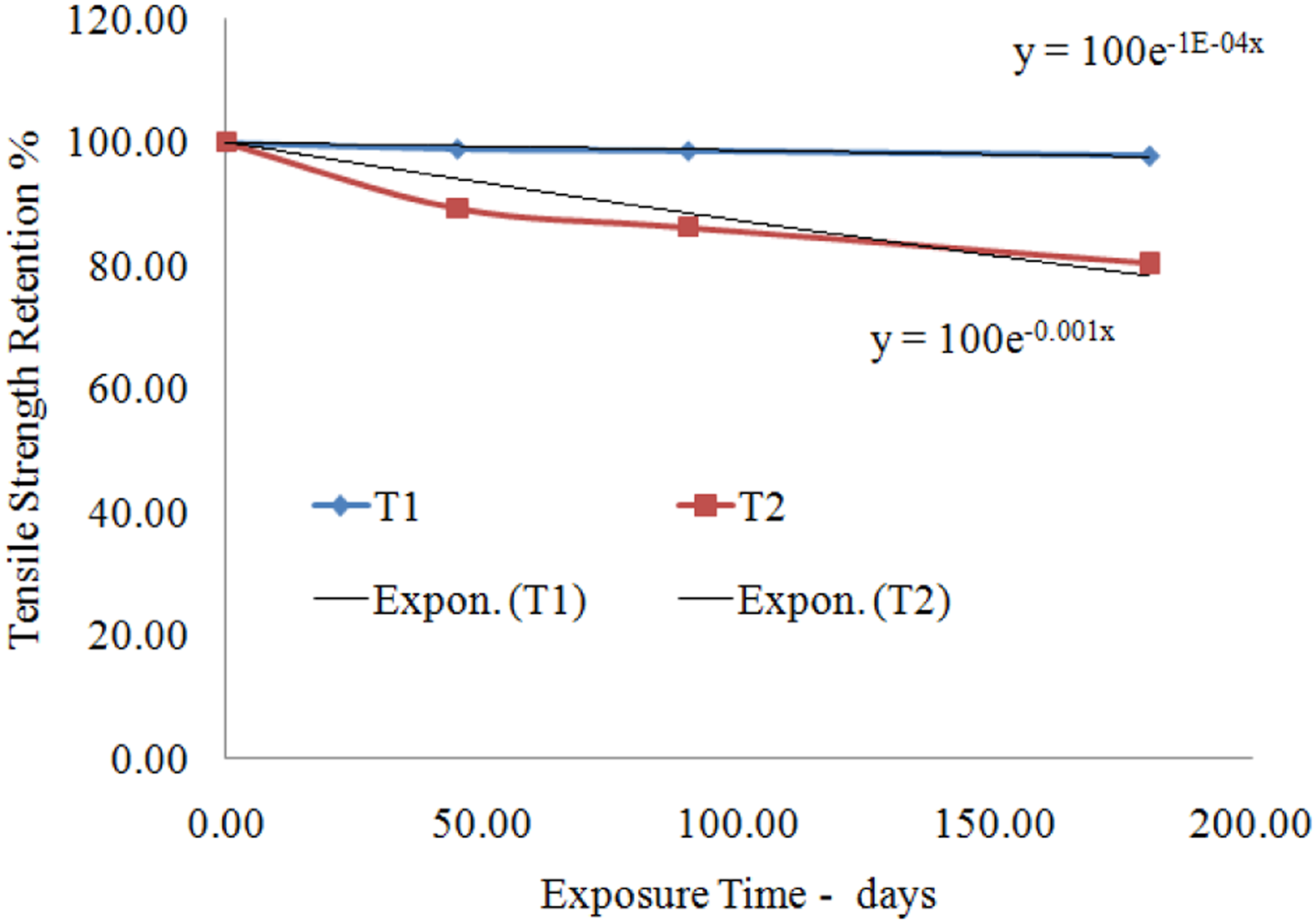
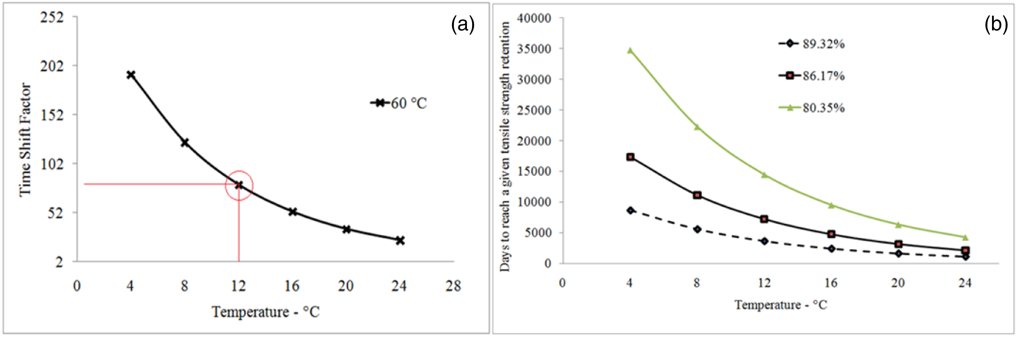
In the same way, based on accelerated ageing for glass/epoxy specimens, the tensile strength retention 78.68% during 45 days, 74.3% over 90 days and 72.42% after 180 days took place at 60°C, corresponding to an ageing period of 913, 1827 and 2737 days at 12°C, respectively. As mentioned earlier, equation (4) with assumption of Y
∞
= 72% and 80% for glass/epoxy and carbon/epoxy, respectively, was used to predict long-term life of the aged composite specimens. Based on fitted curves in compliance with equation (4) and the accelerated ageing for glass/epoxy specimens, the tensile strength retention 78.68% during 45 days, 74.3% over 90 days and 73.14% after 180 days took place at 60°C, corresponding to an ageing period of 3027, 6054 and 12,107 days at 12°C, respectively, with time shift factor 67.26 (Figure 14). Additionally, the accelerated ageing for carbon/epoxy specimens, the tensile strength retention 89.32% during 45 days, 86.17% over 90 days and 80.35% after 180 days took place at 60°C, corresponding to an ageing period of 3604, 7208 and 14,417 days at 12°C, respectively, with time shift factor 80.1 (Figure 15). TSF versus reference temperature at 60°C (Model B) (a), and life prediction of glass/epoxy composite samples (Model B) (b). TSF versus reference temperature at 60°C (Model B) (a), and life prediction of carbon/epoxy composite samples (Model B) (b).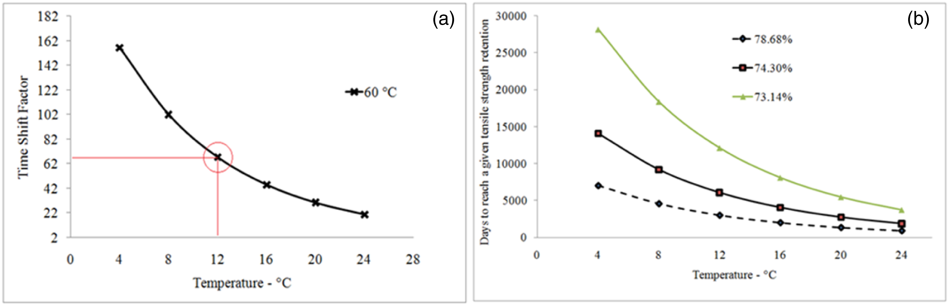
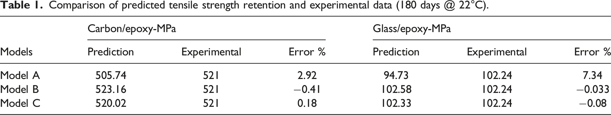
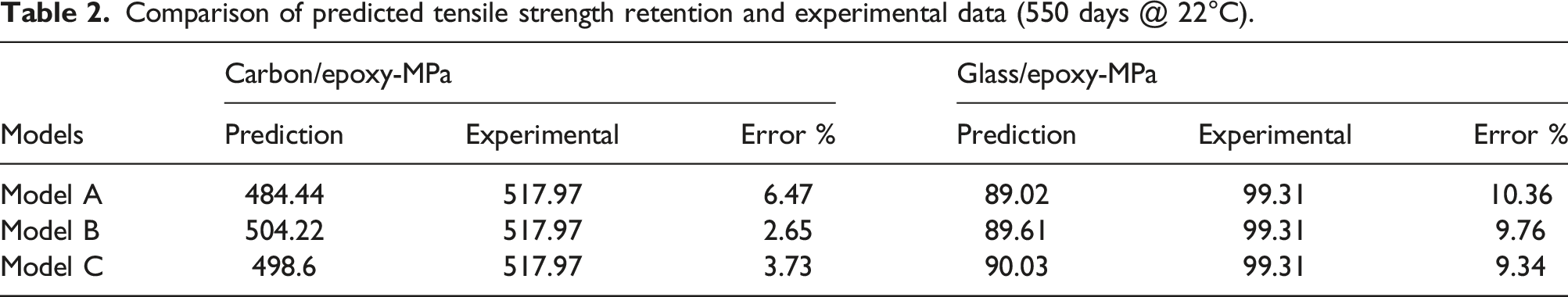
Comparison of predicted tensile strength retention and experimental data (180 days @ 22°C).
Comparison of predicted tensile strength retention and experimental data (550 days @ 22°C).
Multi-scale modelling
In recent years, numerous researches have been concentrated on analysing the response of continuous and chopped fibrous composite materials constituent phases and their interfaces under static and dynamic mechanical loading conditions. Assessment of this includes examining the microstructure of the composite material (matrix surrounded by fibres) and connecting the calculated behaviour to meso-scale or macroscopic behaviour. To facilitate this type of analysis, micromechanical models have been developed which model each constituent as a discrete material and allow for stress distribution, damage and eventual failure of the composite to be simulated at the micro-scale.
29
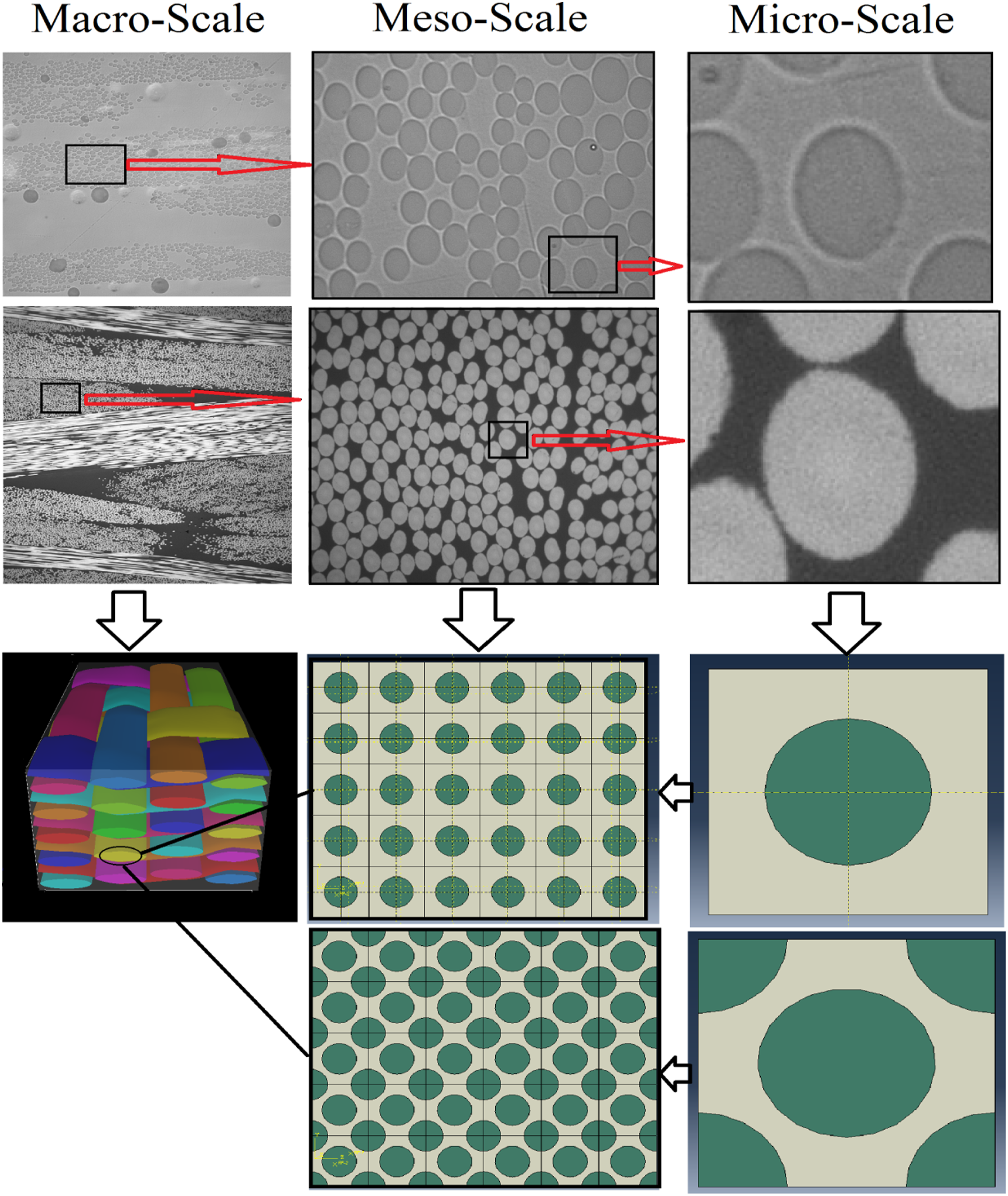
A finite element-based numerical approach such as the representative volume element (RVE) homogenisation method capable of accommodating the effect of geometrical variations of constituent materials at the micro-scale is widely recommended to predict the effective elastic properties of composites, and it is becoming the standard approach for composite materials.30,31 The nano-indentation technique can be implemented to determine in situ mechanical constituent properties to accurately model (RVE) the micro-scale behaviour of composite laminates. In this section, the experimental data collected through nanoindentation testing (micro-scale level) was used to predict the macro-scale properties of composite materials via creating an RVE. In reality, the aligned fibres in a fibre reinforced composite material are randomly spaced within the cross section. For purposes of analysis, however, it is often assumed that the fibers are uniformly distributed in a periodic fashion. Two common packing patterns are the square and hexagonal arrays, as shown in Figure 16. This assumption greatly simplifies the micromechanical analysis, as discussed below.
32
1. The fibers are as follows: (a) continuous, (b) straight, (c) infinitely long in the fibre direction, (d) perfectly aligned with fibre direction axis, (e) circular in cross section and (f) arranged in a periodic square array; 2. The fibre and matrix materials are (a) homogeneous, (b) isotropic and (c) linearly elastic; 3. The fibre and matrix are perfectly bonded at their interface; 4. Mechanical loads are applied at infinity; 5. Loads and material properties do not vary along the fibre direction. Two different RVEs used in the micromechanical model.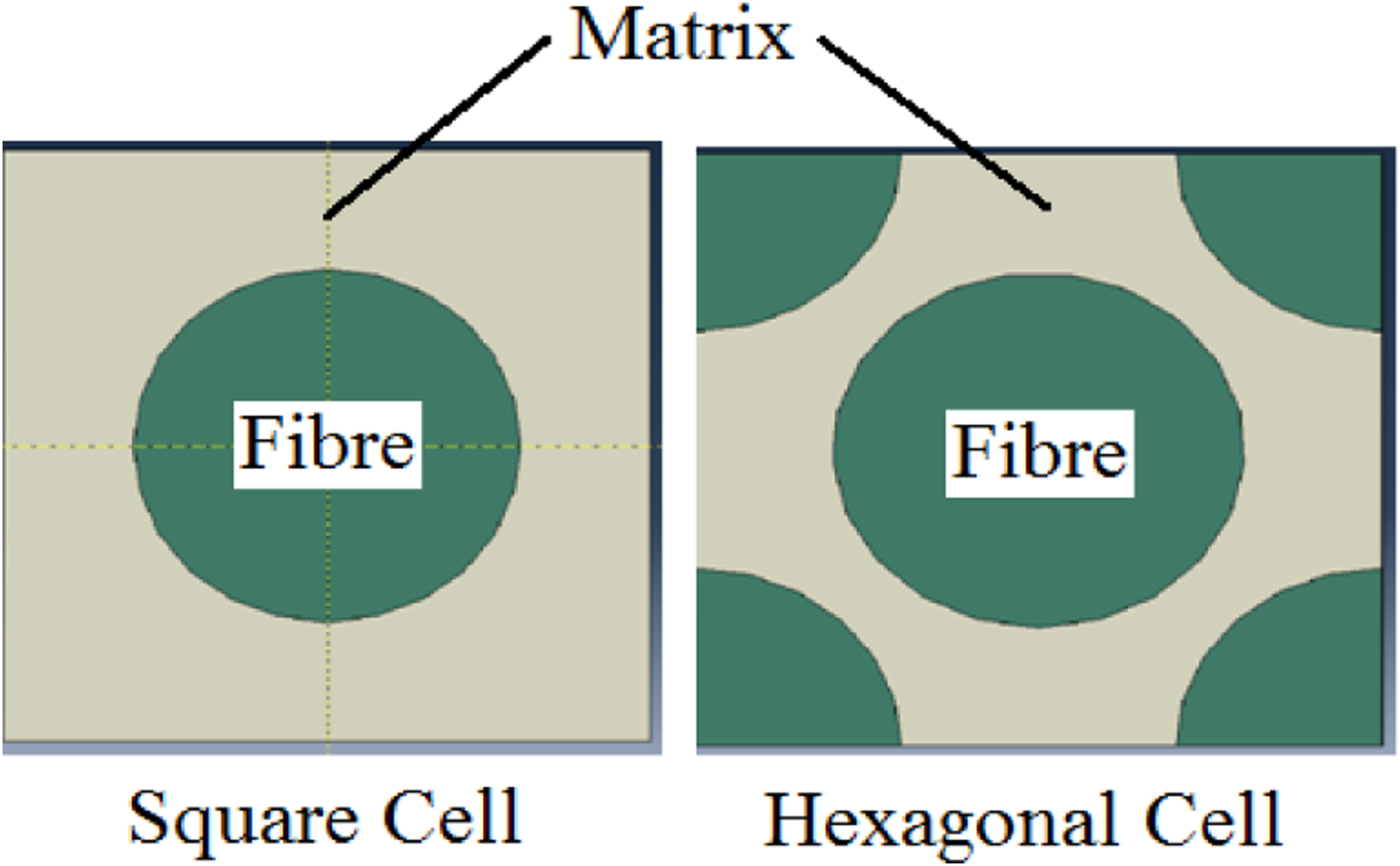
There are some ABAQUS GUIs and plug-ins such as ABAQUS SwiftComp GUI
33
and TexGen4SC
34
used in different literature and applications to measure the elastic properties and multi-scale assessment of composite unit cells. All above mentioned software was used to model RVE unit cells and calculate the elastic properties of glass/epoxy and carbon/epoxy composites via three different approaches (with approximately the same results), 1) create RVE in ABAQUS, apply periodic boundary conditions, and then apply load and calculate the elastic properties, 2) Use TexGen4SC (a combination of TexGen and SwiftComp) and 3) Use RVE in ABAQUS and EasyPBC.
35
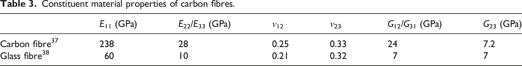
More details of the three abovementioned approaches are explained in the flowchart shown in Figures 17 and 18. Fibres were defined using the elastic properties shown in Table 3 for carbon and glass fibres. The fibre was assumed to exhibit transversely isotropic linear elastic behaviour, while the epoxy resin’s behaviour was modelled as isotropic according to the experimental data from nanoindentation testing (Figure 4). Two different 3D RVE unit cells, square and hexagonal, including fibre and matrix were modelled in ABAQUS. Hexahedral elements properties were used as standard, 3D stress and quadratic with reduced integration, so that total number of elements was 1200 linear hexahedral elements of type C3D20 R (total number of nodes was 5757). After creating the RVE cell in ABAQUS, periodic boundary conditions (PBC) were applied to the RVE. The PBC is a set of boundary conditions that are normally used when the physical geometry of interest and the expected pattern of the solutions have a periodically repeating nature. They can be used to simulate a bulk material by modelling a finite RVE.
36
Flowchart for the three different approaches to implement the modelling. Multi-scale modelling of composite laminates (fibres, yarns, fabrics). Constituent material properties of carbon fibres.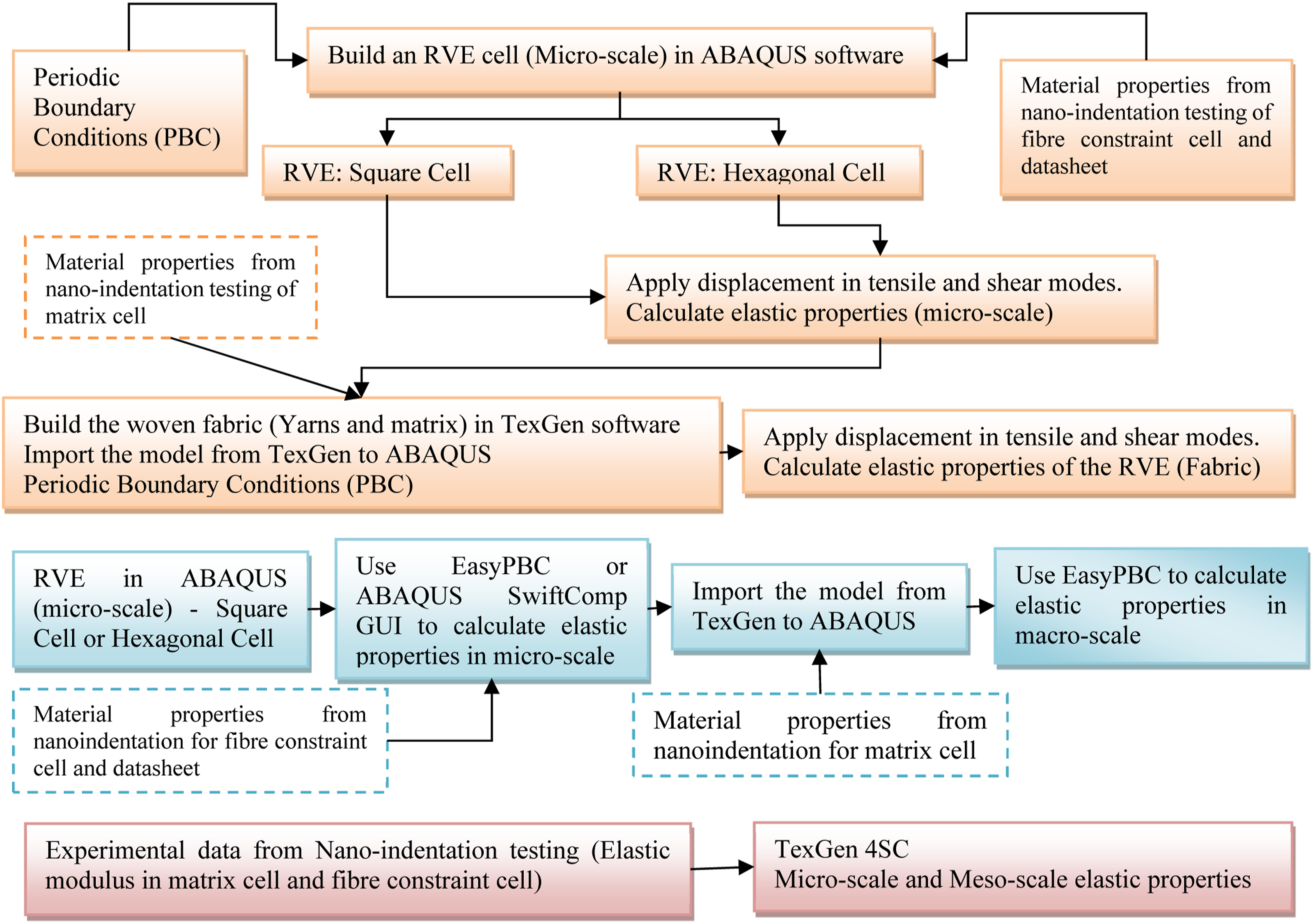
For the RVE shown in Figure 19, the PBC’s can be applied to the RVE to ensure a macroscopically uniform stress or displacement field for tension and shear load (Equations (5) and (6), respectively
39
) Single fibre unit cell with PBCs in (a) shear, and (b) tensile.
39


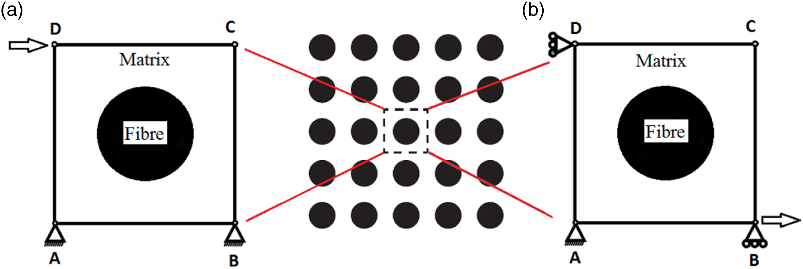
Also, there is another approach to apply the periodic boundary conditions on the RVE cell based on concepts of unified periodic RVE homogenisation.40,41 The concept of RVE homogenisation is to numerically impose uniform strains/displacement to compute the effective elastic properties of a composite model, as can be seen in Figure 20. Schematic representation of displacement boundary conditions required to estimate the effective elastic properties (E = elastic modulus, G = shear modulus, and ν = Poisson’s ratio).
41
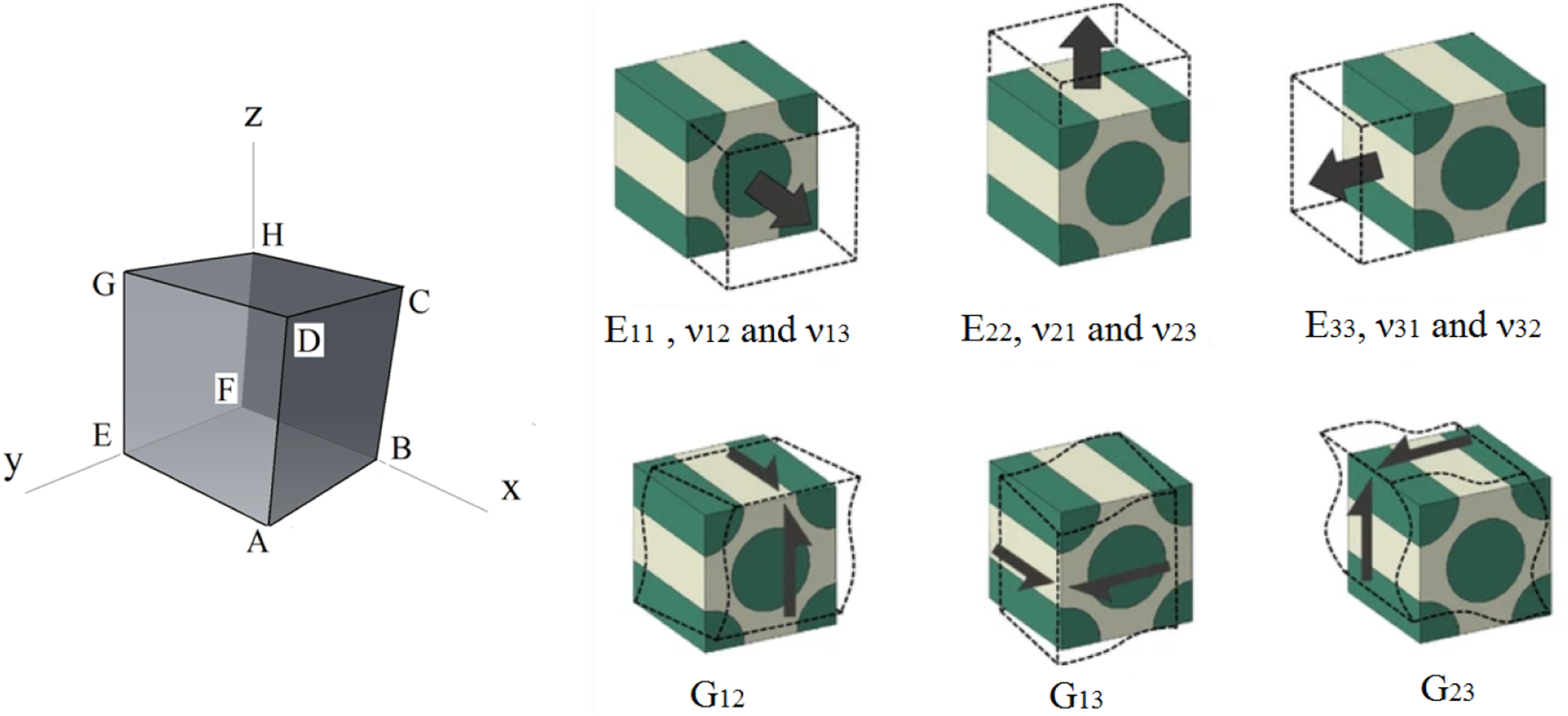
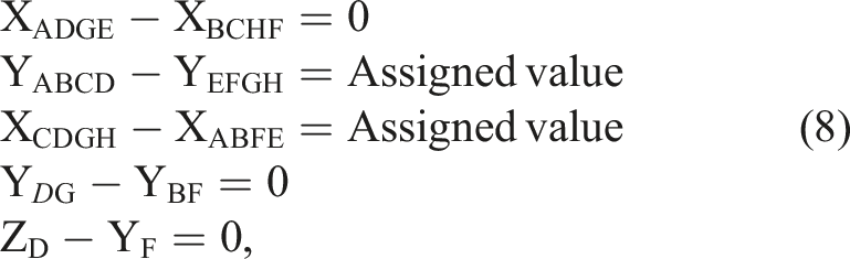
Earlier homogenisation studies achieved periodicity by imposing boundary conditions that ensure RVE’s plane boundary surfaces remain plane after deformation.42,43 This is only correct for a transversely isotropic RVE under longitudinal and transverse strains. 41 However, that is not the case for orthotropic representation and shear modulus estimation, since it will over-constrain the RVE, leading to overestimating the composite elastic properties. 44 Thus, it is necessary to apply node-to-node periodic conditions, at which deformed boundary surfaces can distort and no longer remain plane.45,46 Achieving these periodicity conditions requires linking nodal degrees of freedom in commercial finite element software, based on concepts of unified periodic RVE homogenisation41,44 as illustrated in below equations.
For elastic modulus E11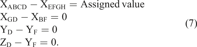
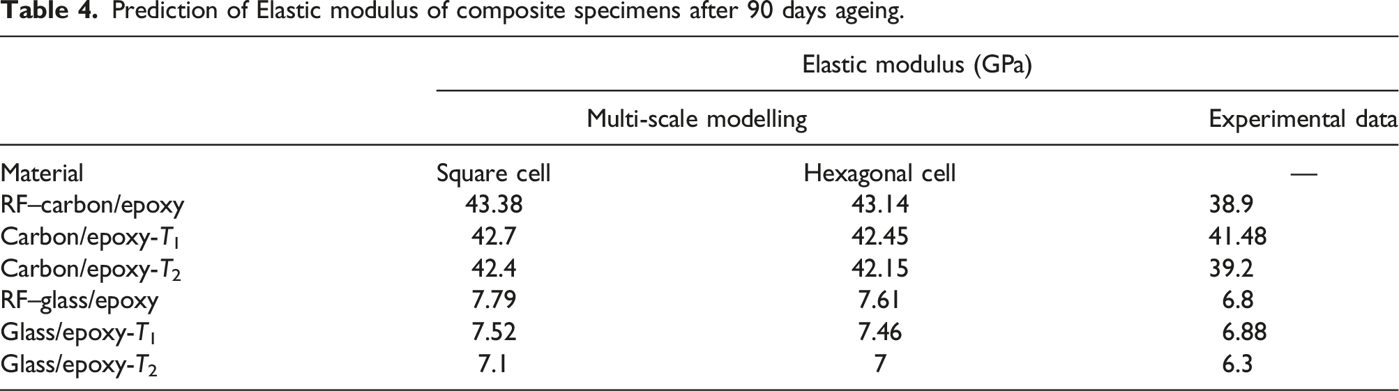
Prediction of Elastic modulus of composite specimens after 90 days ageing.
Conclusion
In this work, tensile strength test and nanoindentation testing have been conducted in order to predict long term life and multi-scale modelling of aged glass/epoxy and carbon/epoxy composite materials. The primary findings of the work are as follows: • The tensile strength in dry glass/epoxy sample was determined as 106.33 ± 1.7 MPa. The tensile strength of glass/epoxy at room temperature after 45, 90 and 180 days was measured as 105.03 ± 2 MPa, 104.4 ± 2 MPa, and 102.24 ± 2 MPa, respectively. Mean tensile strength at 60°C after 45 days immersion in salt water was 83.66 ± 2 MPa. After ageing the glass/epoxy samples at elevated temperature for 90 and 180 days, the tensile strength reduced 25.7% and 26.85%, respectively. • In the same way, tensile strength of carbon/epoxy was determined, obtaining a mean value of 532.64 ± 2 MPa for dry carbon/epoxy specimens. The tensile strength was 475.77 ± 2.1 MPa for aged carbon/epoxy specimens at 60°C, respectively, after 45 days. The effect of seawater on tensile strength after 90 days (459 ± 2.5MPa) and 180 (428 ± 2 MPa) days at elevated temperature was significant. • It was concluded from nanoindentation testing (standard method) that the average modulus of matrix cells in dry glass/epoxy specimens was 4.47 ± 0.5 GPa. After 90 days ageing in room temperature, there was just a very slight drop in modulus (4.4 ± 0.4 GPa), while this value decreased 22.3% at 60°C. • The average value of modulus of matrix cells in the reference carbon/epoxy samples was 4.7 ± 0.3GP, while those values for aged samples at room temperature and 60°C were calculated as 2.875 ± 0.1 GPa (−38.8%) and 2.287 ± 0.1 GPa (−51.3%), respectively. • With regard to fibre constraint cells in carbon/epoxy samples, it is evident that there was no change in modulus indentation (10.6 ± 0.2 GPa) during ageing process at both temperatures, meanwhile regarding the indentation characterisation in glass/epoxy samples, 12.58% (8.89 ± 0.4 GPa) and 25.8% (7.54 ± 0.5 GPa) at room temperature and 60°C reduction was measured compared to the reference specimen (10.17 ± 0.5 GPa). • Three different analytical models were used to predict the long-term life of composite samples. The tensile strength of the carbon/epoxy and glass/epoxy samples was predicted after 180 days ageing in salt water at room temperature to verify the accuracy of the models. The tensile strength of carbon/epoxy samples after 180 days at room temperature was calculated as 521 MPa according to the tensile testing via Instron machine, while this mechanical property was anticipated as 505.74 MPa, 523.16 MPa and 520.02 MPa by model A, model B and model C, respectively. • Likewise, model A predicted the tensile strength of glass/epoxy samples after ageing in the same environment as 94.73 MPa, whereas model B and model C anticipated that this value will be 102.58 MPa and 102.33 MPa, respectively. It should be emphasised that the tensile strength of glass/epoxy specimens in this environment was measured as 102.24 ± 1 via Instron machine. • In general, the implemented multi-scale modelling in ABAQUS and TexGen4SC was able to approximate (with about 10% difference) the mechanical properties of dry and aged composite laminates. • The experimental results presented in Tables 1 and 2 are predicted after only 180 and 550 days (less than 2 years) at room temperature (22°C). The predicted time intervals are close to the almost linear first section of the investigated models. This is why the linear model (model A) showed acceptable results compared to nonlinear models (models B and C). To predict long-term behaviour of composite materials, according to the non-linear degradation behaviour of the materials (tensile strength), models B and C will work with higher accuracy compared to model A. The restriction of linear model for long-term life prediction is assessed (the linear model says after a long time, the tensile strength will reach 0, while it is not in 0v 0076compliance with the reality). As a conclusion, it can be said that for short-term life prediction, the linear model has adequate accuracy but for long-term predictions, models B and C (especially model C) are recommended.
ORCID iDs
Pouyan Ghabezi https://orcid.org/0000-0002-8809-9855
Noel M. Harrison https://orcid.org/0000-0001-5596-2723
Footnotes
Declaration of Conflicting Interests
The author(s) declared no potential conflicts of interest with respect to the research, authorship, and/or publication of this article. The work is also supported in part by a research grant from Science Foundation Ireland (SFI) under Grant no. 16/RC/3872 and is co-funded under the European Regional Development Fund.
Funding
The author(s) disclosed receipt of the following financial support for the research, authorship, and/or publication of this article: This research was funded by Enterprise Ireland through the Irish Composite centre (IComp), Degradation of Composites (DeCay) project (Grant no. TC2014-0017).