
Abstract
Nap-core sandwich, which is lightweight and characterized by many remarkable properties, comes from an extraordinary combination of sandwich-structured composites and textile materials. However, the application of it in industries is still limited due to a lack of understanding its mechanical properties and behaviors. Several studies based on experimentation or numerical simulation have been conducted to fulfill the shortage, and this study is in the mainstream of exploring how the sandwich composite performs when geometries or materials of the nap-core vary. Namely, the comparison of double sided structure and single sided structure used for the nap-core will be presented in this article. The inquiry derives from the fact that a nap-core can take either of the two structures, but the advantages and disadvantages of each have not been identified yet while manufacturers hardly own costly molds for both. Since only the double sided nap-core is actually available, a modeling method is being deployed in Abaqus engineering software to compare it with an equivalent single sided nap-core that is simulated having the same materials and boundary dimensions. Before that, the Representative Volume Element homogenization method was employed to effectively determine engineering constants of the nap-core’s knitted fabric. The final results reveal that the single sided nap-core has better strength than the double sided nap-core in typical loading cases, but it assumes less smooth stress distribution.
Introduction
Sandwich-structured composite (or core materials) is a special class of lightweight engineering composite materials, being created by laying a lightweight but thick core between two thin stiff skins also called outer layers or face sheets. Three pieces are attached to each other with a strong adhesive to create an assembly possessing good out-of-plane compressive strength and high bending stiffness with a marked low density. Generally, the core is made with a hollow structure to minify the weight.1,2 There are various kinds of sandwich-structured composites available according to the skin and core patterns. Thin metal plates, laminates of fiberglass, primarily thermoset polymers (e.g., unsaturated polyester or epoxy), and carbon fiber reinforced thermoplastics are very usual choices for the skin materials. Open- /closed-cell-structured foams and honeycombs are common options for the core.
There are three major factors deciding mechanical properties of a sandwich-structured composite, which are (1) constituent materials of core, adhesive, and skins; (2) geometrical parameters of the skins and the core such as total height, cell wall’s thickness, and cell periodicity; (3) cohesion and interconnection scheme between the core and the skins. 3 For instance, a sandwich with a thicker core often has a higher flexural strength but lower compressive strength. 4 Given to a notable performance-to-weight ratio, sandwich-structured composite materials have been employed more and more in the industry of manufacturing vehicles, spaceships, and aircrafts. Nowadays, most lining elements are fabricated with nonmetal sandwich materials. When altering materials and parameters of the sandwich’s components, the mechanical behavior of it will be different, resulting in a wide range of properties for numerous applications.
Nap-core sandwich composite is a novel kind of cell core materials beside well recognized ones such as foam or honeycomb sandwich composites. Regardless of the initial development in the 1980s, its application has just come to the industries for several years.
5
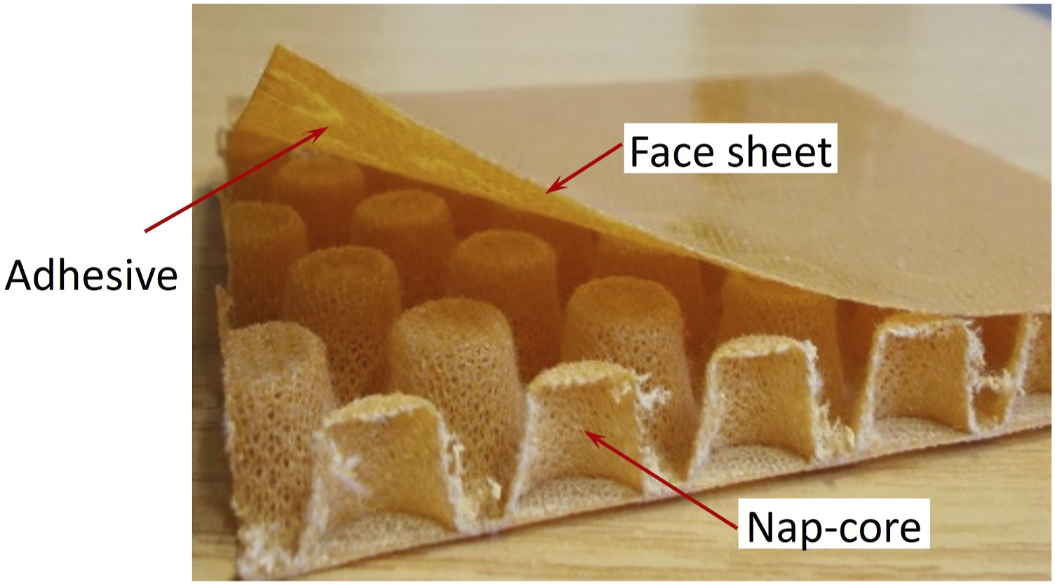
A detailed introduction of nap-core sandwich can be found in previous publications of the authors.6,7 It is worth iterating that nap-core is a semi-finished product and made of 2D knitted fabric which is first pre-impregnated with a thermosetting resin and then formed periodic cups with a pin mold by deep-drawing method. Afterwards, it is cured at high temperature around 140°C for a few hours and cooled down at room temperature to acquire a permanent 3D form. Then the nap-core is laid between two identical face sheets of fiberglass-weaved laminate with thermosetting resin Phenol formaldehyde as the adhesive. That brings about a durable sandwich structure with non-homogeneous support to the skins by the core (see Figure 1). The deep-drawing process provides the core crosswise periodic cup-shaped naps, so it is often called nap-core. Being particularly manufactured, nap-core adopts many desirable physical and chemical properties such as good resistance to abrasion, high inertness to organic solvents, no conductivity, low flammability, and good strength against UV, acids and alkalis.
8
In addition, nap-core sandwich features prominent properties in mechanical and structural aspects such as
9
1. The shape of the nap-core is long-lasting, and the sandwich can be curved or bended at some degree in applications to match surfaces. 2. There is no detachment or dislocation between the yarns or fibers thanks to the locking of thermosetting resin. 3. The voids on the fabric and the hollows between the naps allow the sandwich to be drainage and ventilated to fluids; ducts and wires can be easily integrated inside. 4. By changing the materials and geometries of nap-core and face sheets, numerous kinds of nap-core sandwiches can be made to satisfy different requirements. 5. The production cost of nap-core sandwich is much more affordable in comparison with foams or honeycombs although its specific strengths are somewhat lower. Structure of a nap-core sandwich.
There are many ways of categorizing nap-cores by their differences in geometry, material, nap layout, and knitting pattern. According to the geometry, they can be allocated into two main groups: (1) Single sided nap-core being formed by a positive tool and a negative tool (see Figure 2-right), and (2) Double sided (symmetric) nap-core being shaped by two positive tools (Figure 2-left). The former can be made simply by hand, and it was derived first, while the latter was developed in recent times for automation. In fact, symmetric nap-core is more appropriate for automated production and more efficient at complex drapability as its naps can diverge and converge on both sides. Nevertheless, the geometry of symmetric nap-core is usually limited by the pin sizes that are comparatively smaller and shorter than those used for single sided nap-core. Additionally, the molds for creating symmetric nap-cores are considerably more expensive. Symmetric nap-core (left) and single sided.
The distinctive structure of nap-core sandwich confers various good characteristics, but there has been not much research on it because of the novelty. Bernaschek et al. conducted experiments with static loading to compare mechanical properties of nap-cores and honeycombs and then made a conclusion that nap-cores had smaller specific strength but lower production cost and more prospective for development. 10 Gerber et al. examined the potential usages of lightweight nap-core sandwich and studied the mechanical behavior of paper honeycombs and symmetric nap-core sandwich structures under transient impact. 11 Ha et al. analyzed the performance of nap-core sandwiches via standard tests such as compression, shear, and three-point bending. 5 Regarding to modeling method, Ha and Zehn 6 and Ha et al. 7 suggested a numerical model for simulation of nap-core sandwich composites and used it to effectively predict their mechanical behavior when the materials or dimensions changed. Nonetheless, it still remains a question what differences are in mechanical properties between two sandwiches made with two nap-cores having equivalent materials and dimensions but different structures, that is, symmetric nap-core and single sided nap-core. In this article, simulation method will be engaged to compare mechanical properties of an actual symmetric nap-core sandwich and an equivalent virtual single sided nap-core sandwich. That will help to optimize research and development process significantly because mechanical behavior of single sided nap-core can be predicted in advance without actual samples. Efficiency and strength of some nap-core sandwich explored by its virtual model will be a principal aspect in determining if molds and tools for the production of it will be necessary or not.
Material and experiments
The nap core sandwich behaves differently in all directions, and the most common failures are nap-core buckling due to local or global loading and delamination of the outer layers due to bonding degradation. In order to highlight these failures of the nap core sandwich and check its mechanical properties, three categories of typical tests are performed which are compression, shear, and four-point bending as standard for sandwich core materials. Only influence of static load is concerned in this study. The experimentation is implemented in a closed workshop room in which humidity and temperature are controlled to minify the environmental impact.
Specimens
Specifications of the symmetric nap-core and outer layers.

Out-of-plane compression test
All degrees of freedom of the bottom surface of the sample are constrained while a vertical pressure is evenly distributed on the top surface (Figure 3). The standard for the test is ASTM C365 – 03; the samples are 50 mm long and 50 mm wide. The general scheme of the compression test.
In-plane shear test
All degrees of freedom of the bottom surface of the sample are restricted while surface traction (tractive force) is uniformly and completely applied on the top surface (Figure 4). The standard for the test is ASTM C273/C273M – 20; the samples are 200 mm long and 50 mm wide. The general scheme of the shear test.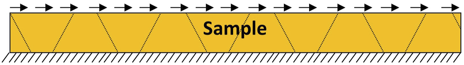
Four-point bending
The bottom surface of the sample is placed on two circular supports 300 mm from center to center. Two concentrated forces are applied vertically and equally to the top of the sandwich through two circular pins 100 mm apart (Figure 5). The standard for testing is ASTM C393 - 00; the samples are 200 mm long and 50 mm wide. The general scheme of the four-point bending test.
The experimental results expose that there is first, in every test, a short interim period in which the relationship between the force and the displacement of the sample is nonlinear. That uprises from the establishment of new contacts for the nap-core is not a continuum. Afterwards, the relationship becomes linear until some damage happens. The damage could be buckling of the nap-core in compression, shear buckling of the nap-core and total detachment of a face sheet in shear, or local debonding of the top face sheet in four-point bending. Thereby, behavior of the nap-core sandwich up to a damage is not as complicated as that of a normal dry knitted fabric (without resin), which is usually non-linear.
In every test category, the force changes slightly from sample to sample with a spread between 4%–6%. Thus, the resulting experimental force is taken as the average force value of the five specimens. This will be used to compare with the simulation force attained in the next section.
Additionally, drum peel test on samples of dimensions 240 mm × 75 mm under standard ASTM D1781 – 98 (2012) is also accompanied only for the determination of the cohesive parameters needed for the sandwich modeling. The testing scheme is shown in Figure 6. In practical drum peel test, the upper end of the sample is fixed by the peeling apparatus’s top clamp, and the lower end of the sample is firmly attached to the drum’s clamp. The sample is additionally bonded to a backing plate. To conduct the test, the top clamp is suspended from the testing machine’s upper head while the drum rolls up. The general scheme of the drum peel test.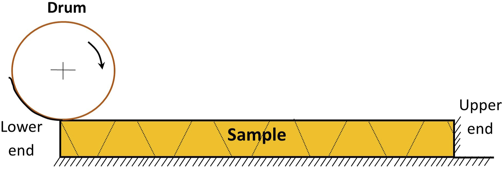
Numerical modeling methods
This section mainly focuses on the comparison between symmetric nap-core sandwich and single sided nap-core sandwich by modeling method. The numerical models of the concerned symmetric nap-core and the equivalent single sided nap-core are represented in Figure 7. Models of the symmetric nap-core (left) and the single sided nap-core.
The nap-core sandwich model
A nap-core sandwich is generally a composite formed by three components (two stiff skins and a nap-core) that are fabric composites. In addition, the knitting pattern of nap-core has already become non-uniformly deformed after the deep drawing process. Thus, the overall structure of the nap-core sandwich is exhaustively complex, and a detailed modeling of it would be extremely costly and challenging. Fortunately, experiments presented in Material and Experiments discover that the nap-core behaves very much like a thin and continuous sheet although its cured fabric is discontinuous and inhomogeneous. Hence, the authors approach the simulation by modeling all the components as deformable shells where the materials are assumed to be orthotropic instead of anisotropic as in practice.
Of every component, the thickness is smaller than one-fifteenth of the span, so the transverse shear effect can be disregarded, and it is able to be modeled as a thin shell needing imposition of only in-plane material properties. 13 As a result, the number of engineering parameters to be determined drops from nine to four, and they can be quantified by uncomplicated experiments. In practice, two in-plane tensile moduli (E1 and E2) and one Poisson’s ratio (ν12) are often measured with the application of standard DIN EN ISO 13934-1 for textile fabrics, while the corresponding shear modulus (G12) is attained with a picture frame shear test according to DIN SPEC 4885/DIN EN ISO 20337 standards.
By the deep drawing process, the nap-core can be seen consisting of three unlike segments: the top, the wall, and the bottom (see Figure 7-left). These segments have dissimilar degrees of extension and contraction. Moreover, the wall stands alone while the top and the bottom attach firmly to the faces with a good adhesive. By performing various simulations of tension, shear, and bending tests, it is revealed that the wall accounts for about 98% strength of the nap-core. Thus, only the engineering parameters of this segment are needed, and they can be appointed to the whole nap-core for the sake of simplicity.
Besides the measurement tactic, the authors also develop a modeling method to obtain the nap-core wall’s engineering parameters. This depends on the Representative Volume Element (RVE) homogenization method with the assumption that the knitting structure of the wall can be divided into repeating elements; each element contains all the features of the whole wall and is called RVE.14,15 This homogenization method is chosen because its application is relatively simple but efficient and powerful. 16 By successfully modeling the RVE, all its engineering parameters are determined, and they are exactly those of the nap-core’s wall. The full RVE homogenization method consists of three steps and has been demonstrated
By modeling the RVE successfully, all engineering parameters of it are determined and they are exactly those of the nap-core’s wall. The full RVE homogenization method includes three steps and has been presented in.6,7 It can be summarized as follows.
Step 1. Choose the representative volume element for the nap-core’s knitted fabric
RVE can be chosen in any way complying with the requirements that it is periodic and consists in all the structure’s engineering parameters under any boundary condition. Because the nap-core wall is the primary segment, the RVE of its knitted fabric can be used to characterize the entire nap-core. The selected RVE is displayed in Figure 8-left. The real RVE (left) and the simulation RVE embedded in a void box using periodic boundary conditions (right). RVE: representative volume element.
Step 2. Generating the FE model of the representative volume element
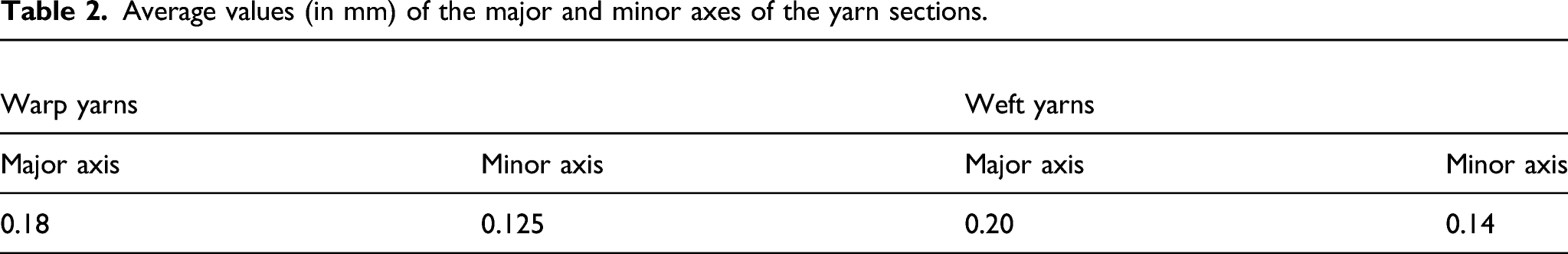
To build an FE model of the RVE, the most straightforward method is making use of a CT scanner but it is pricey and unneeded in this case. Instead, an ordinary microscope is engaged to determine the swept directions and diameters of the warp yarn and the weft yarn of the RVE, that is, a minimum of 9 discrete points is achieved for each yarn. Subsequently, the full shapes of the yarns are reconstructed in Abaqus from the coordinates of the measuring points. To accomplish accurate results, the yarn models need to be made as swept solids or beams with the transverse shear stiffness. Eventually, a cubic box of a tiny elastic modulus material is produced to embed the fibrous RVE. The cubic box is unrealistic, but it is necessary for the imposition of periodic boundary conditions on the RVE while its impact on accuracy of the results can be omitted. For the selected nap-core in the study, the RVE’s boundary is 1.129 mm wide, 1.743 mm long, and 0.445 mm thick. When the RVE model is established, conventional simulations are implemented on it to find the engineering parameters, including two in-plane tensile moduli, one corresponding shear modulus, and one Poisson’s ratio. The resulting parameters are noticed to converge when the mesh seed of the yarns is less than 0.015 mm.
Step 3. Boundary conditions and computation
Common choices of boundary conditions are periodic boundary condition, constant traction boundary condition, and linear displacement boundary condition of which the first one is usually regarded as the most effective by many studies. It even bring about proper result when some geometrical periodicity is missing at the microscopic level.17,18 Periodic boundary condition requires the same FE discretization on each couple of facing surfaces of the RVE. Every couple of opposite nodes are assumed to have equal displacements that can be described as


Average values (in mm) of the major and minor axes of the yarn sections.
Mechanical properties of the nap-core’s constituent materials.

For modeling compression and shear tests on the RVE to determine the engineering constants, the boundary conditions are the same as those used in the experiments described in Material and Experiments. Namely, one face of the void box embedding RVE is securely constrained while pressure or traction is imposed on the opposite face. At last, the homogenized engineering constants of the symmetric nap-core’s fabric are accomplished from the simulations on the RVE, providing E1 = 43.85E7 (Pa), E2 = 34.26E7 (Pa), G12 = 121.15E7 (Pa), and ν12 = 0.28. Besides, engineering constants of the face sheets are measured according to standard DIN EN ISO 13,934-1, offering E1 = 4.28E9 (Pa), E2 = 4.12E9 (Pa), G12 = 2.45E9 (Pa), ν12 = 0.28. Here, 1 and 2 subscripts denote X and Y in Figure 8, respectively.
Cohesion parameters
Two face sheets and the nap-core are affixed together by an adhesive, and the cohesive strength is particularly critical in resisting shear or bending loads. In the simulation, two similar cohesive layers of the nap-core sandwich are modeled as thin bonding layers. Their major parameters have been estimated by peeling tests based on the classical study on cohesiveness done by Alfano and Crisfield.
21
The cohesive elements are imposed “traction-separation” property with the quadratic traction-interaction failure criterion (Quads damage) for the damage initiation; the damage evolution and propagation is described using energy-based law and the power law criterion. All input parameters of the adhesive material are shown in Table 4, where Enn – Young’s modulus along the normal direction; Gss – Shear modulus along the local first direction; Gtt – Shear modulus along the local second direction; N0 – Nominal stress in Normal-Only-Mode; T0 – Nominal stress in the First direction; S0 – Nominal stress in the Second direction of the cohesion damage; G1C – Fracture energy in Normal Mode; G2C – Fracture energy for the first direction in Shear Mode; G3C – Fracture energy for the second direction in Shear Mode; α – Power of the damage evolution, equal to 1.45 for all the nap-core sandwiches. (Note that the unit of fracture energy is J/m2 which is equivalent to N/m). Cohesion parameters of the nap-core sandwich (adhesive thickness = 0.01 mm).

Sizes of the simulation models
The sizes of the simulation models and the computation times.

Results and discussion
Parameters of the nap-core in the comparison.

The major differences between the two nap-cores are their structures, that is, two-sided structure against one-sided structure. The sandwich models of the two nap-cores are created with Abaqus using the simulation method presented in Numerical Modeling Methods. All the engineering parameters of the symmetric nap-core sandwich’s components and the adhesion will be imposed on the sandwich models of the single sided nap-core. The face sheets of them are exactly the same. All selections are to minimize the error caused by the other aspects and concentrate on the structural difference of the two nap-core types.
To compare these two nap-cores, simulations of the typical tests given in Material and Experiments, which are compression, shear, and four-point bending, have been implemented on their sandwich models. The results of the experiments for the symmetric nap-core sandwich and the simulations for both nap-core sandwiches are supplied hereafter.
Out-of-plane compression:
Figure 9 exhibits experimental result and simulation result of the compression test. For the symmetric nap-core sandwich, the simulation model and the experimental sample have close moduli and forces, but the displacement at buckling of the model is pretty larger than that of the sample. Also, the model buckles more difficultly than the sample in the damage. Compression simulation results of the sandwich samples with the symmetric nap-core (red) and the single sided nap-core (blue).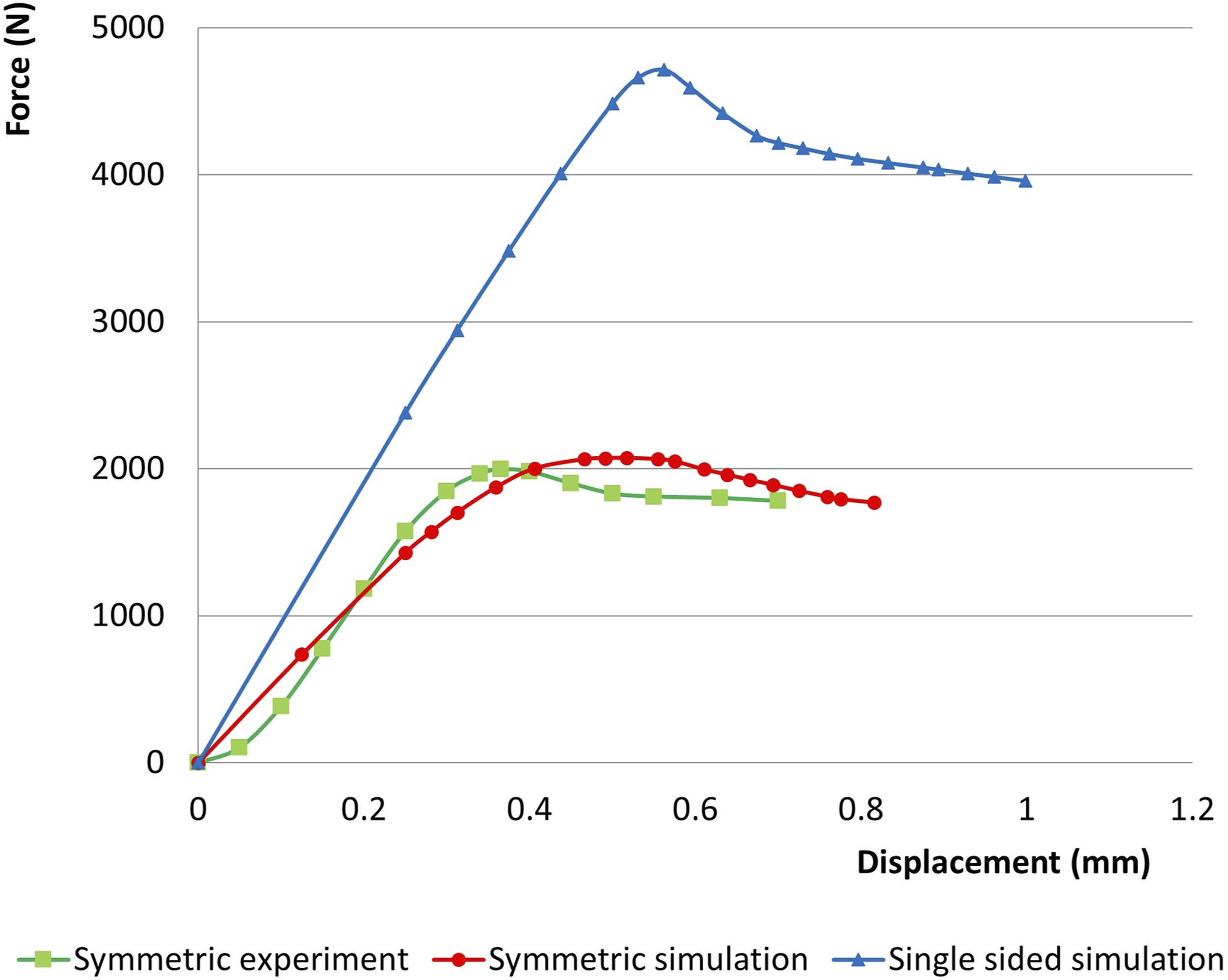
It is obvious that strength and elastic modulus of the single sided nap-core sandwich prevail over those of the symmetric nap-core sandwich. Additionally, the maximum force of the single sided nap-core sandwich is much better than that of the symmetric nap-core sandwich while its displacement at buckling is only a bit larger, that is, 4713.5 N and 0.58 mm compared to 2072.9 N and 0.52 mm.
The buckling schemes of the sandwich samples during the compression simulations are illustrated in Figure 10. In both cases, the buckling initiates at the middle of the naps. However, the stress distribution is symmetric for the double sided nap-core while it is much bigger at the top half for the single sided nap-core. The buckling of the nap-cores in the compression simulations: Symmetric nap-core (top) and the single sided nap-core (bottom).
In-plane shear
Results of the shear experiment and simulation are displayed in Figure 11. For the symmetric nap-core sandwich, both experimental sample and simulation model show very high shear strength and elastic moduli. The force and displacement at shear buckling of the model are pretty larger than those of the sample, but the dissimilarities are less than 10%. Shear simulation results of the sandwich samples with the symmetric nap-core (red) and the single sided nap-core (blue).
The charts demonstrate that the performances of the single sided nap-core sandwich and the symmetric nap-core sandwich in the shear simulation are not as different as they are in the compression simulation. The equivalent elastic modulus of the single sided nap-core sandwich is smaller as its chart is further to the vertical axis, but the maximum force and the displacement at buckling of it are bigger than those of the symmetric nap-core sandwich, that is, 5249.4 N and 1.25 mm compared to 4988.8 N and 0.80 mm. Thereby, the displacement at buckling of the single sided nap-core sandwich is much bigger.
The buckling schemes of the sandwich samples during the shear simulations are illustrated in Figure 12. Once again, it is found that the stress distribution of the double sided nap-core is much more uniform than the single sided one. The deformation of the nap-cores in the shear simulations: Symmetric nap-core (top) and the single sided nap-core (bottom).
Four-point bending
The four-point bending results can be found in Figure 13. For the symmetric nap-core sandwich, the simulation model has the maximal force smaller than that of the experimental sample. Besides, its delamination the top layer occurs earlier and more slowly, so the force of the model does not decrease as sharply as that of the sample after the damage begins. Four-point bending simulation results of the sandwich samples with symmetric nap-core (red) and the single sided nap-core (blue).
Similar to the compression, the single sided nap-core sandwich also works much better than the symmetric nap-core sandwich in the four-point bending simulation as its maximal force is clearly higher, yet the displacement at buckling of the former is only a little bigger than that of the latter, that is, 137.4 N and 4.30 mm compared to 67.9 N and 4.05 mm. The elastic modulus of the single sided nap-core sandwich is the greater one as well.
The deformations of the two nap-core sandwich models are showed in Figure 14. The symmetric nap-core bends rather more than the single sided nap-core sandwich, and the stress distribution of it is more dispersed. The deformations of the nap-core sandwich samples in the four-point simulations: Symmetric nap-core (top) and the single sided nap-core (bottom).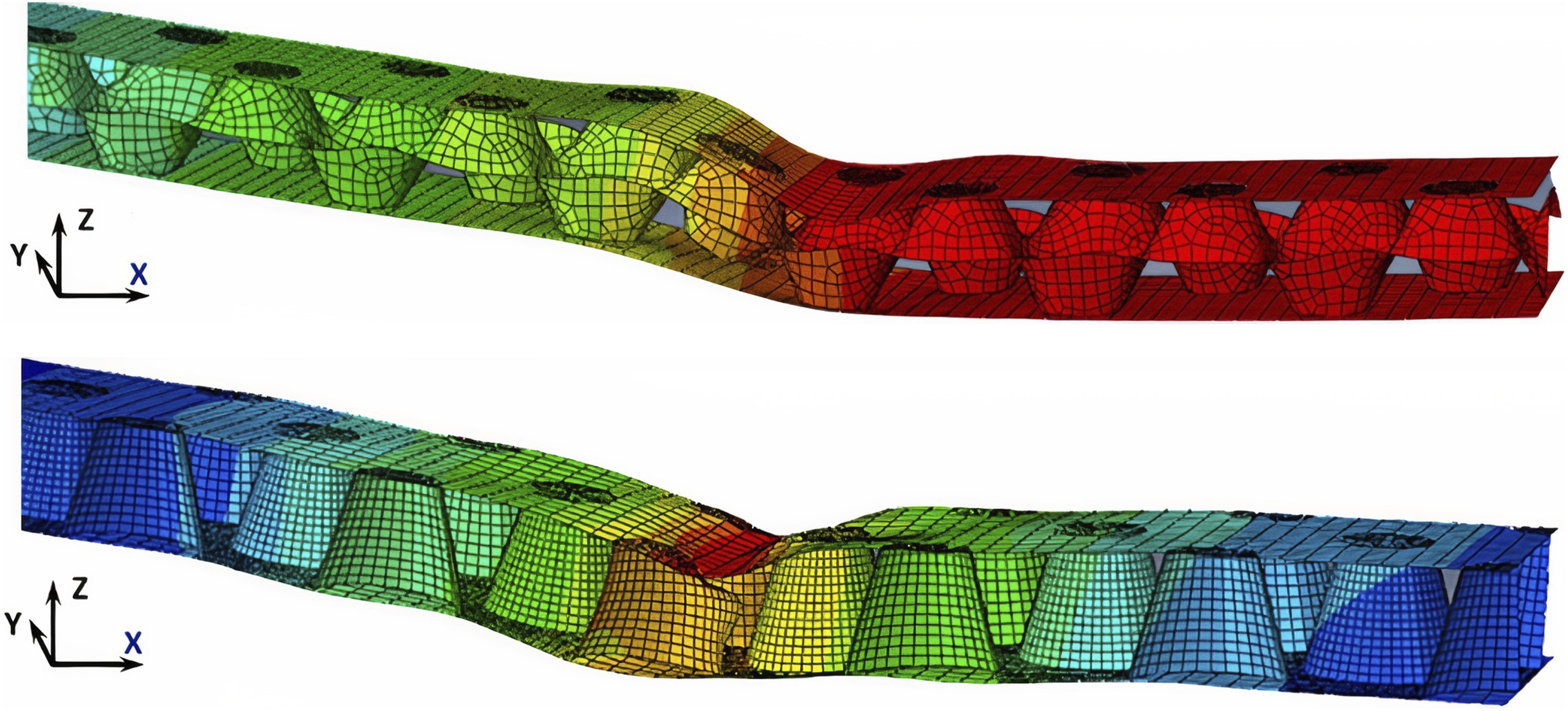
In comparison between the experiment and the simulation of the symmetric nap-core sandwich, the experimental sample and the simulation model in compression have similar points of damage initiation while their damage evolutions are quite different as the simulation model is stiffer. In fact, not all failure mechanisms of the nap-core sandwich have already been fully understood, and they need further exploration. However, the simulation did accurately determine positions on the nap-core with the most concentrated stress. The simulation model performs a little better in the shear and bending than the compression as it can depict well both linear stage and non-linear stage of the deformation as well as buckling of the nap-core and debonding of the upper skin.
In comparison between the single sided nap-core sandwich and double sided nap-core sandwich, it is noted that the former works better than the latter in all three kinds of tests. In the compression and the four-point bending simulations, the maximum force of the single sided nap-core sandwich is approximately double that of the double sided nap-core sandwich. In the shear, the force is equivalent but the displacement at buckling of the former is about 50% higher than that of the latter. The superiority of the single sided nap-core sandwich is probably explained by the gradual increase of the nap section when traveling from the top to the bottom. On the other hand, the nap section of the double sided nap-core increases from one end to the middle and then decreases from the middle to the other end. Therefore, the single sided nap-core can reach to a bigger nap section that offers more support, making the whole sandwich sturdier. However, it is reminded that the symmetric nap-core is developed because it is more suitable for the automatic mass production, and its naps can converge and diverge on both sides that permits complex drapability. Besides, there are many ways of improving the quality of a symmetric nap-core by having better materials, adhesive, or geometries.
Generally, the simulation method efficiently proves that the single sided nap-core sandwich dominates double sided nap-core sandwich in all cases, especially in compression and four-point bending.
Conclusions
The nap-core sandwich is a lightweight material that is considered a combination of textile materials and sandwich-structured composites, possessing various properties desired to mechanical applications. Particularly, it can overcome the problems of foam and honeycomb core sandwiches, which are difficulties of ventilation and wire integration. The nap-core sandwich also fits both manual fabrication and automated production. Nonetheless, the application of the nap-core sandwich in industries is still not commensurate with its potential because there is deficient knowledge of its mechanical behavior. Exploiting FE modeling is one of the best ways to squeeze more understanding on this novel structural composite.
Through simulations, it is noted that the strength of the single sided nap-core sandwich is superior to that of the symmetric nap-core sandwich in all three kinds of tests. In the compression and the four-point bending simulations, the maximum force of the former is approximately double that of the latter. In the shear, the displacement at buckling of the former is about one and a half time of that of the latter. That also means the single sided nap-core sandwich is stronger and tougher to different loadings. Nonetheless, stress distribution of the double sided nap-core sandwich is much better, and it is very efficient at preventing or moderating local damage and bucking. In the shear, elastic modulus of the symmetric nap-core sandwich seems to be better than that of the single sided nap-core sandwich. Additionally, the symmetric nap-core is more suitable for the automatic mass production. It permits the knitted fabric to converge and diverge on both sides of the core, so the deformation and stretching of the fabric are more uniform.
The RVE homogenization method is an appropriate and affordable tool for simulating and investigating mechanical properties and behaviors of the nap-core sandwich for its efficiency and straightforward application. The nap-core sandwich structures have proven good specific strength and endurance in diverse loading cases although the range of their knitted fabric’s elastic moduli is rather small. By employing simulation strategy, not only can performance of the nap-core sandwich under various conditions be anticipated, but also mechanical properties and behavior of the nap-core sandwich corresponding to changes of its geometries or materials can be well estimated. This is exceedingly helpful for proposing optimal designs as well as most suitable materials for the nap-core sandwich in each case of usage.
Footnotes
Acknowledgements
The authors would like to thank the Institute of Mechanics of the Technical University of Berlin, Fraunhofer Pyco and InnoMat GmbH for profound advice on preparing and testing nap-core sandwich samples.
Declaration of conflicting interests
The author(s) declared no potential conflicts of interest with respect to the research, authorship, and/or publication of this article.
Funding
The author(s) received no financial support for the research, authorship, and/or publication of this article.