
Abstract
To date, discarded tires are reused in many applications, however, because of the enormous quantity decommissioned annually, it is essential to continue researching new recycling methods as well as applications to reduce waste and preserve new resources. In the present study, a simple recycling technology of end-of-life tire (ELT) powder is proposed, and the influence of steel slag as filler is assessed. Europe produces about 7 Mt of steel slag annually, and although most of it is reused as an artificial aggregate, about 15% is still landfilled. Also in the case of steel slag, the study of new applications is mandatory so that the combination of these two waste materials, in a 100% recycled composite fits across different industrial sectors facing the same environmental issue. It was found that the leaching of the slag incorporated in the rubber matrix is reduced and that the ELT powder recycled by this technology gives rise to a well-cohesive material. A good rubber-filler interaction was found by swelling test and differential scanning calorimetry (DSC) analysis. The slag reduces the friction coefficient and increases the thermal conductivity. The experimental results showed how some properties of recycled ELT can be improved by adding the steel slag.
Keywords
Introduction
About 65% of all natural and synthetic rubber compounds produced are consumed by the tire manufacturing industry 1 and globally, it was valued that over 1.5 billion end-of-life tires (ELTs) comprising about 40% of vulcanized rubber is discarded every year. 1 As the rubber tire is designed for high durability and abrasion resistance, its reprocess is very difficult and over the years the simpler way of landfill disposal has been preferred. The ever growing demand for new tires together with the non-biodegradable nature of ELTs made landfilling a non-sustainable waste management method. 2
Sustainable management of tire waste is driven by legislation that encourages the shift from landfilling to energy and material recovery processes, as well as by private organizations seeking to manage the sustainability of their supply chains. 1 When a tire loses the essential characteristics for a safe and efficient performance on the vehicle, without the possibility of retreading, it becomes a special non-hazardous waste and must be collected for recovery and recycling in special plants.
Every year in Italy, there are about 435.000 t of used tires, of which about 20% are sent for retreading because they are still usable. On the other hand, there are approximately 350.000 ELTs: half of them are destined for energy recovery; about 25% are recovered as material and the remainder is dispersed.
The rubber compound of which the tire is made is in fact a mixture of high-quality polymers with exceptional chemical-physical characteristics that remain unchanged even in the recycled rubber compound obtained from them. This is an issue if the tire is dispersed in the environment, in fact the average decomposition time exceed one hundred years, in addition to the fact that it takes up a lot of space, pollutes, and represents a potential fire risk; on the other hand, it is an advantage if it is recycled.
In Europe, Directive 2000/53/EC is mainly aimed at preventing the production of waste deriving from vehicles, including tires (classified as CER 160103), and at promoting reuse, recycling, and other forms of recovery. Before a product becomes waste, it is necessary to take all necessary measures to reduce the amount of waste generated, prolong its life, reduce the harmful effects on the environment, and the risks to human health. Secondly, the reuse of partly worn tires through the retreading is highly recommended to avoid premature disposal. When tires can no longer be restored for their original purpose as they could compromise safety, they can take the path of material recovery. With this action, product goes through a mechanical process to change its form into particles, which are then used in different application. If there are no suitable conditions for the previous type of recovery, the other option besides landfilling is energy recovery. This means that ELTs are used as fuel substitutes due to their high calorific value. Fuel derived from tires (TDF) has a higher calorific power than coal and is also less harmful to the environment due to lower emissions into the atmosphere because of thermal treatment. End-of-life tires disposal in the landfills is the last option but it is not recommended. End-of-life tires occupy a large portion of valuable space in the landfills, store water, and create a breeding habitat for rodents and insects, and are exposed to a considerable risk of fire and combustion. 3
As regards the material recovery, the ELT is sent to special plants which, through mechanical grinding at room temperature, reduce it into smaller and smaller fragments, up to the separation of the three main components of the tire: rubber, steel and textile fiber. 4 With recycled rubber from ELTs, sustainable products are made, which are used in very different sectors. From building products such as acoustic and anti-vibration insulators, 5 to sports, playgrounds, soccer fields, multipurpose sports flooring, and products for animal welfare (rubberized floors that prevent the animal from slipping). Another important sector of use of ELTs is that of roads and infrastructures where, in addition to silent and long-lasting “modified” asphalts, there are cycle paths, street furniture, and elements for road safety.6–9
These most common applications of ELT powder either use this material as a filler or a virgin polymer, such as EVA (Ethylene-vinyl acetate), is used as a binder.
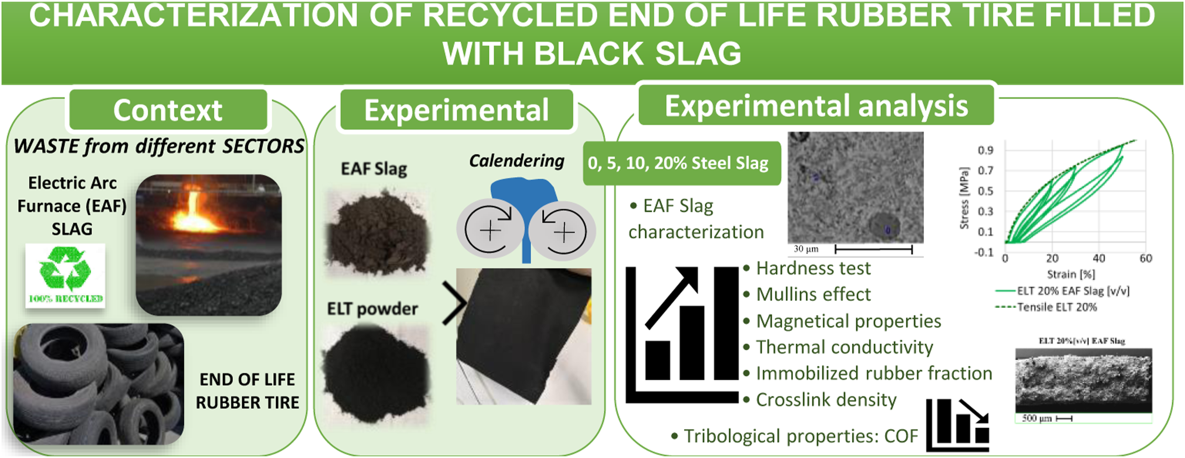
This study represents the characterization of recycled ELTs applying a very simple technology, at room temperature and without additives: calendering in an open mixer. The recycled and compounded rubber thus obtained was mechanically and thermally characterized. In order to enhance some properties, recycled ELT was filled with another waste material such as electric arc furnace slag (EAF) resulting in 100% recycled material combining the waste of two traditionally dissimilar sectors such as that of steel and that of rubber-plastic.
Europe produced in 2020 about 7.5 Mt of EAF slag (consisting in 10–15% of the produced steel).10,11 Due to its mechanical properties and chemical composition similar to that of effusive rocks, the steel slag can find usage in numerous fields of application, mainly as substitute aggregate in road construction, cement, and concrete production,12–16 nevertheless still about 15% is disposed of. 17
The main critical issues related to the reuse of slag are volumetric instability due to the hydration of components such as free lime, and the leaching of heavy metals harmful to humans and the environment. Both phenomena are linked to the interaction between the slag and water and the incorporation of slag particles in a hydrophobic elastomeric matrix reduces this interaction.18–21 The leaching behavior of the slag as filler was investigated according to the standard CEN-EN 12457-2.
Recently, a new application of slag has been introduced as a filler in polymeric matrices18–21 and, specifically, the addition of rigid slag particles in the rubber compounds reduces the space within which the rubber can stretch during the calendaring, with a consequent increase of the shear stress which in turn promotes the mechanical devulcanization and so the forming of the material.
The obtained results showed that the leaching behavior of the slag incorporated in the recycled ELT were evaluated showing a reduction in Cr, Mo, and V leaching as well as in eluate’s pH and electrical conductivity. EAF slag leaching behavior was also studied in terms of mineralogical phases: they were analyzed by Scanning Electron Microscope (SEM) before and after leaching, highlighting how the larnite is completely dissolved.
As regards the assessment of the composite, a mechanical characterization was carried out in terms of hardness and tensile properties; in addition, the viscoelastic behavior of the material was also investigated through cyclic tests (Mullins effect). It emerged that the ELT recycled through this simple technology becomes a well-cohesive and compact material so as to present the viscoelastic effects typical of elastomeric materials and that the slag content at small deformations does not significantly affect the properties of the material except for an increase of hardness.
In order to investigate possible applications for this material, tribological tests were also conducted in different configurations. The friction coefficient is reduced by the slag content while the specific wear rate is a function of the slag content and the configuration of the test. Finally, it was shown how the slag confers the rubber magnetic properties and increases the thermal conductivity making the material interesting for applications where the rubber is required to dissipate heat.
Materials
End-of-life tire powder
The rubber powder used was supplied by the Ges.Tyre Scrl consortium (Brescia, Italy), a consortium company that provides an efficient service for the collection and recovery of ELTs in strict compliance with the regulations and with the utmost respect for the environment and the health of citizens.
From the industrial bag with an average particle size of 0.5 mm, only the particle size less than 0.5 mm was sieved in the laboratory. This powder was used to produce ELT specimens filled with EAF slag.
Electric arc furnace slag
The slag was supplied by the company ASONEXT Spa (Ospitaletto BS, Italy) and has been produced by a specific system named Slag-Rec. 21 A manual pulverizing mill HSM 100 provided by Herzog (Osnabrück, Germany) was applied to grind the slag in a suitable particles size to be employed as filler for a grinding time of 25 s. Pulverized EAF slag has been sieved to obtain a grain size <106 µm.
C ompound ELT filled with EAF slag
The compound ELT filled with EAF slag has been obtained via calendering process utilizing a calender provided by Gaoge-tech instrument (Dongguan, China). This process consists in forcing rubber and slag between two rotating cylinders. During calendering, the rubber is processed in several steps which the temperature increases up to 70–80°C due to the high shear stresses generated. The compounding process has been carried out as first to transform the ELT powder into a single and workable compound thanks to a partial mechanical devulcanization, and secondly to distribute and disperse the slag particles into this polymeric matrix. This process allows to obtain a rubber sheet of about 1 mm as shown in Figure 1. Compounds production steps: EAF slag and ELT powder are compounded via calendering process in several steps up to obtaining a rubber sheet.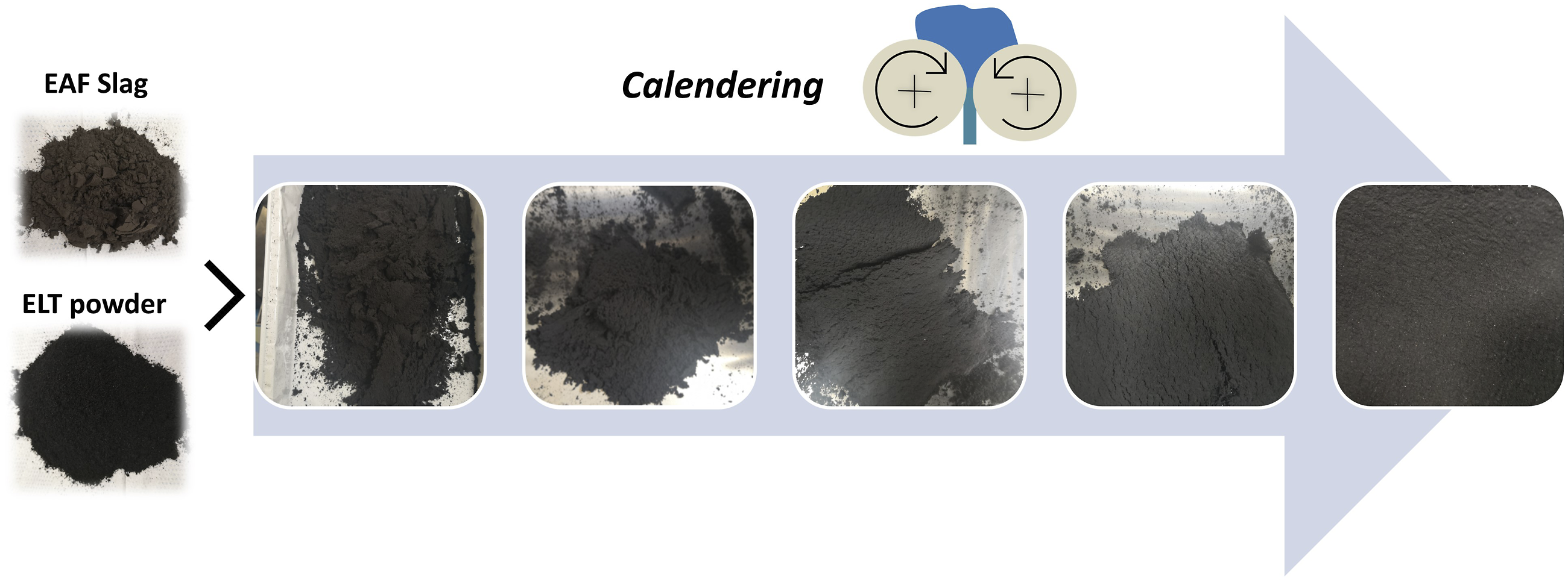
Known the density of ELT from previous measurements (1.13 g/cm3), the quantity of rubber powder and EAF slag has been determined. The influence of EAF slag as filler for ELT has been evaluated on different compounds with and increasing amount of filler: 0, 5, 10, and 20% by volume.
Methods
Electric arc furnace s lag characterization
X-ray fluorescence spectroscopy
EAF slag chemical composition determined by X-ray fluorescence spectroscopy and basicity indexes.
Scanning Electron Microscope (SEM-EDXS) analysis
A SEM integrated with Energy Dispersive X-ray Spectrometry (EDXS) for the morphological and elemental analysis of the phases
22
was adopted to characterize the chemical composition and the phases of the slag. The identification of the phases and structure of the slag was carried out by SEM-EDXS (SEM Leo Evo 40, Carl Zeiss, Oberkochen, Germany; EDXS microprobe Link Pentafet Oxford mod 7060; Oxford Instruments, Oxfordshire, U.K.) on a slag sample prepared by a standard metallographic polishing procedure. In Figure 2, the SEM-EDXS analysis carried out on a metallographically polished sample utilizing back-scattered electron (BSE) mode is reported. The same sample has been analyzed after a leaching for 24 h in H2O to investigate the changes in morphology and chemistry of phases. SEM back-scattered electron (BSE) image of slag microstructure with its EDXS analysis on metallographically polished before and after leaching. All results are in weight %.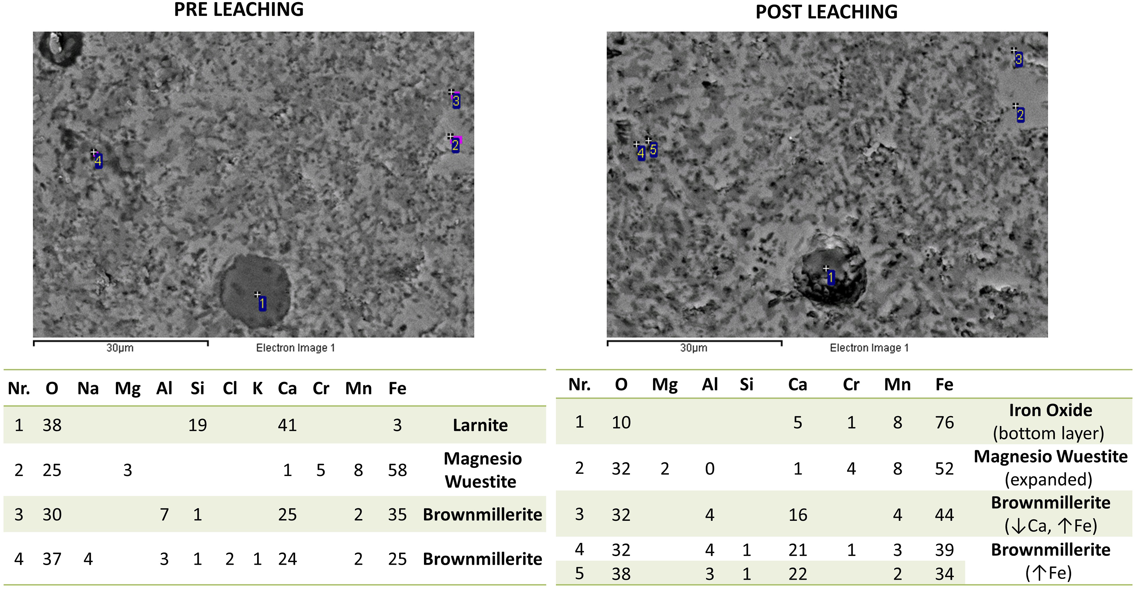
Leaching behavior
The leaching of heavy metals has been determined following the procedure proposed by the standard CEN - EN 12457-2
23
and on the EAF slag in grain size lower than 106 µm in order to compare the leaching of free slag and slag incorporated into the rubber matrix at equal conditions. Since according to literature20,24 lower grain size implies higher leaching of heavy metals, the same test was conducted on both free slag in grain size lower than 0.106 mm and the same size incorporated into ELT matrix. The results are shown in Figure 3. Leaching test results of free EAF slag and EAF slag incorporated into ELT matrix at 20% v/v.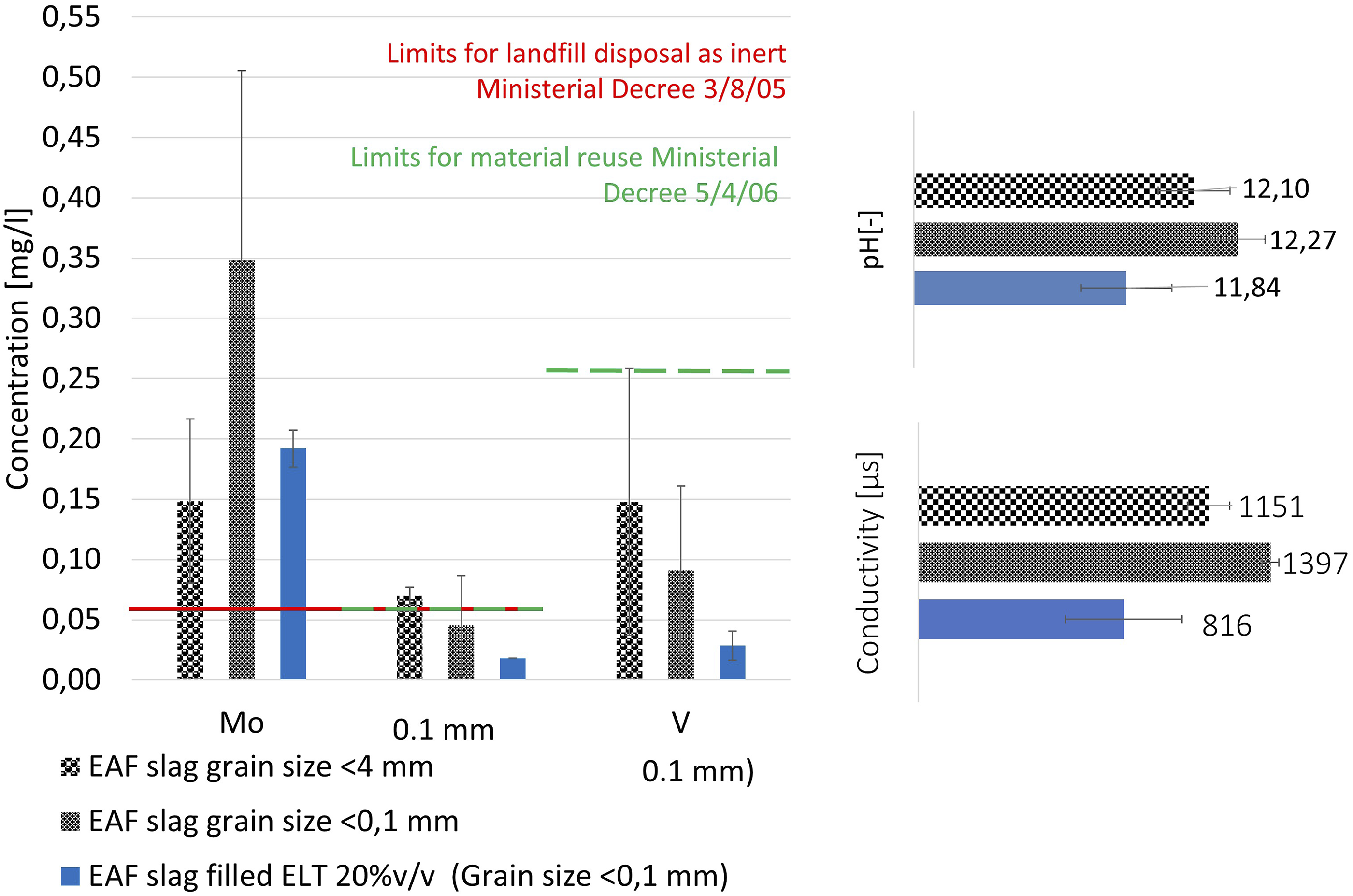
Leachates have been analyzed by an Avio 200 ICP Optical Emission Spectrometer Perkin Elmer (Milano, Italy) to measure the concentration in the solution Cr, Mo, and V. Two leachates were prepared and three analyses were performed each. Leaching test results are given in Figure 3.
Compound characterization
The composition of the recycled ELT was investigated by thermogravimetric analysis (TGA) performed on thermogravimetric analyzer Q500 provided by TA instruments (New Castle, Unites States). Samples of about 10 mg mass were placed in a platinum crucible and heated in a thermobalance at rate of 10 °C/min from ambient to 560°C in nitrogen atmosphere. When the sample mass became constant, the sample is kept for 2 min at 560 °C, and in oxygen atmosphere it is heated up to 800 °C at 10 °C/min in order to facilitate the carbon black content measurement. Thermogravimetric analysis scan is shown in Figure 4. TG and DTG curves of recycled ELT sample and its components decomposition in %wt.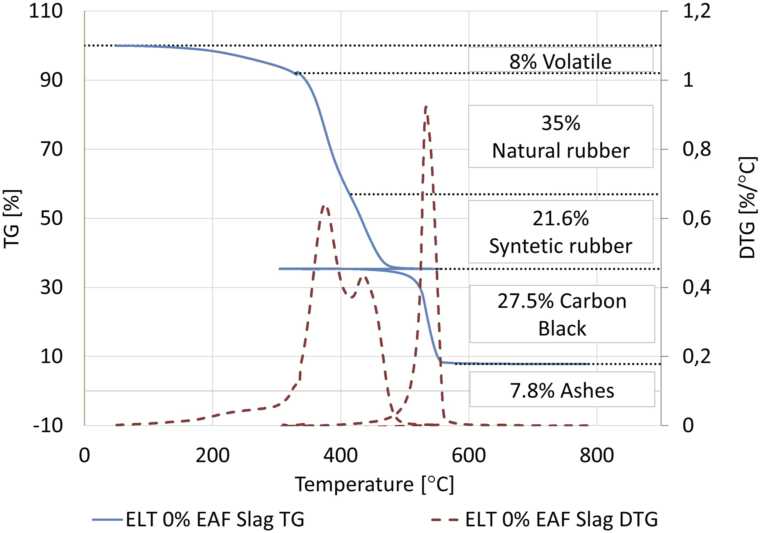
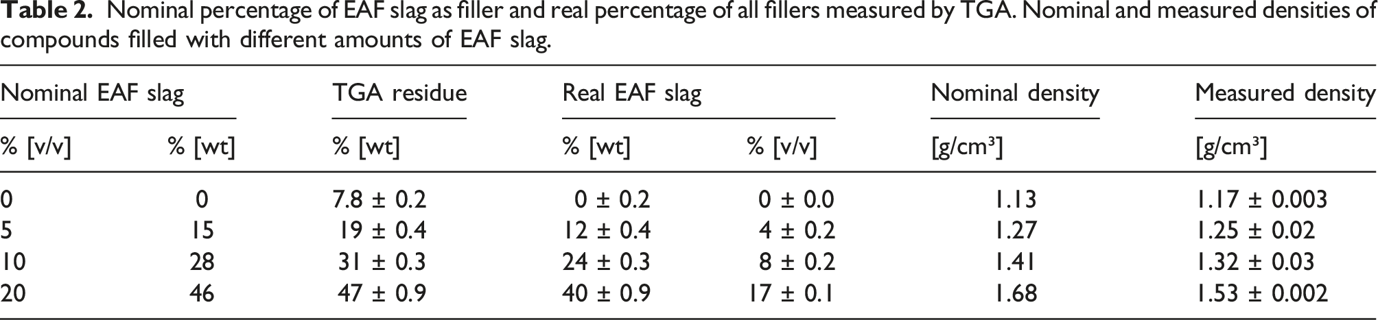
Nominal percentage of EAF slag as filler and real percentage of all fillers measured by TGA. Nominal and measured densities of compounds filled with different amounts of EAF slag.
Mechanical properties
Hardness test
The compounds' hardness was measured according to the micro International Rubber Hardness Grade (mIRHD according to the standard ISO 48. 26 The mIRHD measurements were carried out by an automatic hardness tester Micro IRHD-PC provided by Gibitre Instruments (Bergamo, Italy).
Tensile test
Mechanical tensile tests were performed by an Instron dynamometer (mod. 3366) at room temperature and at a cross-head rate of 100 mm/min on test pieces of 50 mm length (distance between the grips of about 30 mm) and 4 mm width according to the standard ISO 37:2017 type 2. 27 Considered strain is the optical one in order to exclude the influence of the sample edges. Each compound was tested three times. The modulus has been determined as the slope of the stress-strain curve in correspondence of the initial linear section (about 5% −0.2 MPa).
Scanning Electron Microscope analysis
The morphology and distribution of slag particles in the ELT composites were assessed by SEM observations of cross sections of specimens tested in tensile test after coating the surface with sputtered gold.
Mullins effect
Mullins effect was evaluated in a cyclic uniaxial tensile configuration. A rectangular specimen of a nominal dimension 50 × 5 × 1 mm was tested by an Instron dynamometer (mod. 3366).
The maximum strain has fixed at 20%, 30%, and 50% and it was increased every four cycles at a strain rate of 80 mm/min (the maximum speed without having the inertial effect of the cross-head in correspondence of the direction reversal that causes anomalies in the stress-strain curve in the unloading phase).
Magnetic properties
The presence of iron/iron oxides in the slag gives the composite magnetic properties. Magnetic attraction force was evaluated by quantifying the force required to detach a magnet from the ELT filled with different amounts of EAF slag. Therefore, a magnet was fixed to the beam of the dynamometer, which was in contact with the material. The beam was moved at a speed of 10 mm/min and a 500 N load cell detected the load every 0.01 s. Finally, the peak of the curve obtained is identified as the detachment load.
Swelling
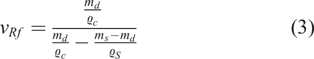
For the swelling test rectangular samples of about 500 mg (m
0
) were cut and immersed in toluene for 96 h at room temperature. The sample was then wiped to remove the toluene on its surfaces and quickly weighed to measure the swollen weight (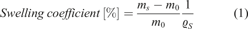
Equilibrium swelling index is determined by crosslink density and the attractive forces between solvent and polymer. The theoretical extent of swelling is predicted by the Flory–Rehner equation28–30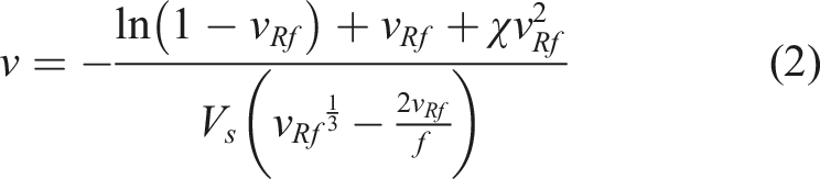
where,
The properties of filled elastomers are linked to the interaction between filler and matrix which can be theoretically estimated by Kraus equation
32
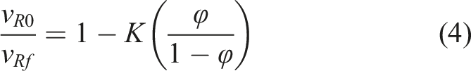
where,
K is the polymer-filler interaction parameter;
The more negative change in free energy values indicates better compatibility between the filler and the matrix.32,33 An increase in entropy shows the disorder of the system which also reveals the enhanced compatibility.
Differential scanning calorimetry
The calorimetric glass transition was determined utilizing differential scanning calorimetry (DSC). Measurements were carried out in the temperature range from −90 °C to 80 °C, in nitrogen atmosphere (purge) by means of DSC (Model: Q100 provided by TA instruments (New Castle, Unites States)). The samples were cooled from room temperature to −90 °C at 10 °C/min and held at this temperature for 60 min at the end of each cooling cycle followed by subsequent heating at 10 °C/min. Differential scanning calorimetry analysis was performed twice.
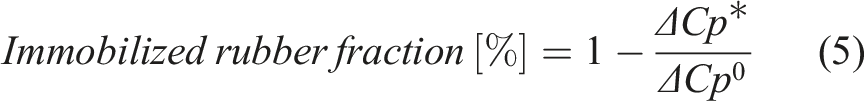
The heat flow [mW] is converted to heat capacity (Cp [J/(g °C)]). End-of-life tire composite samples consist of a weight fraction of filler and a weight fraction of polymer; since only the latter is responsible to the variations associated to the glass transition, the heat capacity has been normalized to the polymer fraction.Where Cp is the heat capacity associated to the composite, Cp* is that associated to the polymer fraction. The filler weight fraction is determined by TGA.
The heat capacity increment, ΔCp* as a measure of the amount of polymer which participates in the glass transition is dependent on the intermolecular rigidity, that is, the polymer-filler interaction in the filled rubber.
34
ΔCp* is determined in a temperature range of ±4°C with respect to the glass transition temperature (Tg). The dependency of ΔCp on intermolecular rigidity is often evaluated in terms of immobilized polymer chains in the composites and is calculated by
35
Tribological properties
The wear tests were conducted on a CSM Instruments High Temperature tribometer (Diepoldsau, Switzerland) in single-way and reciprocating configuration. A 5 mm diameter flat pin (100Cr6) was used as a counterpart as well as a normal load of 5 N, a sliding speed of 80 mm/sec, and a total sliding distance of 156 m were applied at room temperature. The rubber compound disk was cut by the rubber sheets obtained by calendering process as described in 
Finally, the wear track was examined by SEM LEO EVO 40 VPS equipped by EDS probe and the wear mechanisms were studied.
Thermal conductivity
The guarded heat flow meter DTC-300 (TA Instruments, New Castle, USA) operates at steady-state and employs a heat flux transducer to measure the heat flow through the specimen. A sample with a diameter of Ø50 mm and a maximal thickness of 2 mm is mounted between an upper “hot” and a lower “cold” plate. Considering the low thermal conductivity of rubber compounds, that is, 0.15–0.4 W/mK,
36
a sample thickness of 1–4 mm is recommended, as otherwise it can take a long time before thermal equilibrium is reached. In addition, the contact resistance is kept low by applying a pneumatic load of 0.16 MPa and in case of no smooth surface thermal conductivity paste is used. During the measurement, the heat flows from the upper “hot” plate, throughout the specimen, to the lower “cold” plate, establishing a temperature gradient. After reaching thermal equilibrium, the temperature difference across the sample (ΔT) and the resulting heat flow (
The heat flow meter method corresponds to ASTM E1530 37 with an indicated accuracy of + -5%. Based on the investigation of the thermal conductivity of seven rubber compounds, 36 one sample is sufficient, as the deviation is in general significantly smaller than specified in the ASTM E1530 standard.
Thus, one sample with a diameter of Ø50 mm (thickness between 1–2 mm) was punched out of each crosslinked ELT test plate to measure the thermal conductivity at 35°C.
Results and discussion
Electric arc furnace slag
X-ray fluorescence spectroscopy
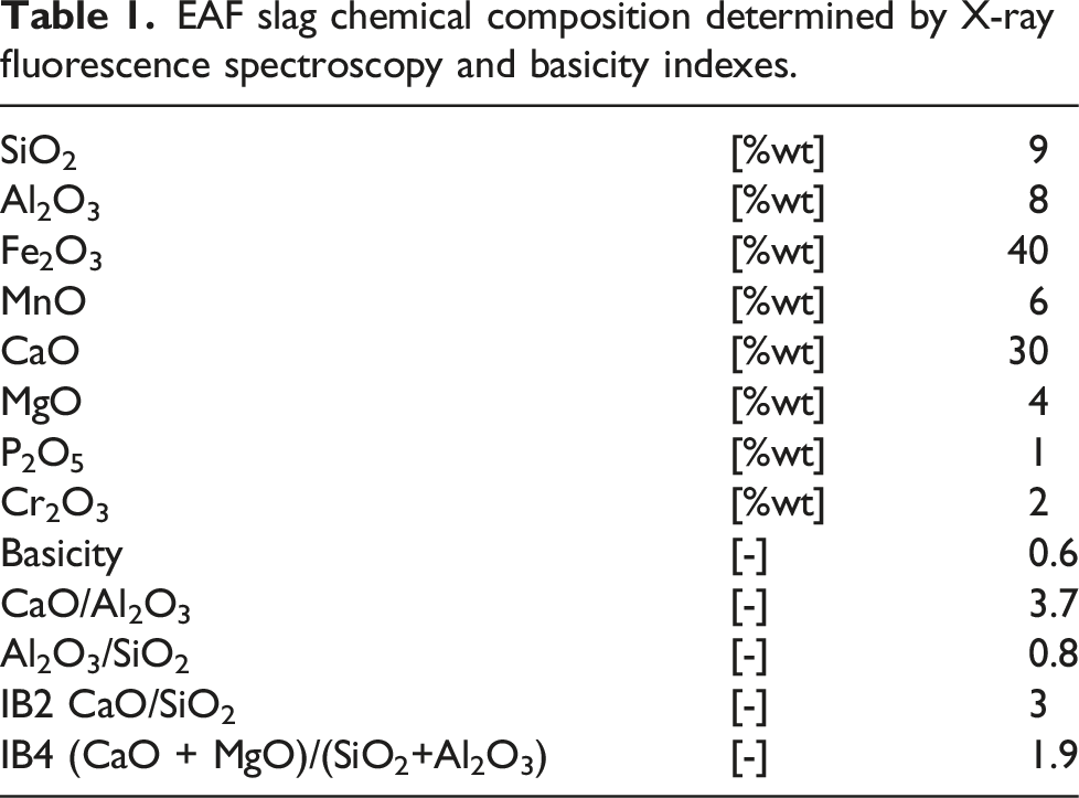
In Table 1, the chemical composition of the EAF slag used as filler is reported.
The ratio between the percentage of basic and acidic components, named basicity index (IB), allows to express and interpret important metal-slag balances, such as the oxidizing power of the slag, the desulphurization balance, and the dephosphorization, metal-slag distribution of manganese.
There are mainly two expressions of IB: the simplest one consists in the CaO and SiO2 ratio and is named IB2; in this slag, it is equal to three. The more complete one is IB4 that considers the presence of other components, and it is defined as the ratio between principal basic oxides (CaO + MgO) and main acid oxides (SiO2 + Al2O3); here, IB4 is equal to 1.9. The basicity of the slag is required in steelmaking because usually furnace refractories are basic too, and a basic slag can extend their useful life preserving their integrity for longer with consequent economic benefits.
Electric arc furnace slag chemical composition is important not just because it affects the chemical composition of the liquid steel but also because affects the leaching of heavy metals. It is important to highlight that the slag leaching behavior is influenced by the cooling it undergoes: a rapidly cooled slag is inclined to form a glassy phase which shields the heavy metals and prevents them from leaching. 38 Tossavainen et al. 38 observed that if the basicity factor IB4 is greater than one the glassy phase formation occurred so that the slag will have low leaching rate (here, IB4 is 1.9).
Scanning Electron Microscope (SEM-EDXS) analysis
Figure 2 shows the micrographs of the same EAF slag sample subjected to phases’ chemical and morphological analysis before and after leaching. The morphological structure of the slag phases is strongly affected by the cooling rate it undergoes after the de-slagging phase. In turn, the morphological structure and so the chemical composition affect the leaching behavior: cooling control conditions can represent a strategy to influence the mineral transformation and the solubility of elements such as Cr, which is crucial for problems involving human health and environmental protection. 39 The analyzed slag shows very fine and dendritic phases, a sign of a rapid cooling with some areas characterized by a single larger phase.
It is possible to state that the global morphology of the phases has not been heavily altered by contact with water, but that the most significant change is represented by a large phase (Spectrum Nr 1), identified as larnite, which is completely dissolved leaving a hole such that the analysis in the same area reports the identification of iron oxide on the bottom layer. This result agrees with the research of Gelfi et.al. 39
The phase in correspondence of the spectrum Nr 2 is rich in Fe and Mg with other elements in trace. This phase has been identified as Magnesium-Wuestite and it is slightly larger after leaching. Despite this, other areas of the same shade of gray (and therefore presumably characterized by the same chemical composition) are less wide. This could indicate a uniform consumption of a few nanometers in the leaching.
As last, the third identified phase is Browmillerite particularly reach of Ca that maybe attributable to near areas of Larnite that due to the fine phases’ morphology affect the EDS signal. The zone identified by the spectrum Nr 3 after leaching reduces the amount of Ca and increases that of Fe, while the zones Nr 4 and 5 are slightly richer in Fe.
Both, the chemical and morphological analysis of the slag indicate a low leaching of heavy elements, a result confirmed by the leaching test (Figure 3).
Leaching behavior
Since the EAF slag derives from a melting process of ferrous scrap, it can contain elements that are dangerous for the environment and for humans. These elements deriving from the alloying elements added on purpose in the composition of the original product in order to achieve certain properties.
For this reason, EAF slags which are not classified and commercialized as by-product are classified as waste which CER codes 10 02 02 “Untreated slag,” CER 10 09 03 “Fusion slag,” and CER 10 02 01 “Wastes from waste treatment.” According to the Italian regulation, when the slag is classified as waste it must be compliant to the Ministerial Decree or for material reuse 19/05/06 “Identification of non-hazardous waste subjected to simplified recovery procedures,” 40 or for landfill disposal 30/08/2005 “Definition of eligibility criteria for landfill waste.” 41 Both decrees bases the slag characterization on leaching behavior according to the standard CEN-EN 12457-2. 23
It was found that with decreasing the slag grain size the leaching of Mo increases as well as pH and conductivity. By incorporating the slag particles into the ELT matrix, the leaching of Mo, Cr, and V is reduced (in particular, the Cr leaching fall within the threshold limit for material reuse), and also pH and conductivity are markedly reduced thanks to the shielding ability of the matrix.
Compound characterization
Figure 4 shows the recycled ELT sample decomposition TG and DTG curves. It illustrates the four components of rubber tire that correspond to its decomposition: volatile, rubber, carbon black, and ashes weight fraction.
The first weight loss corresponds to the emission of volatile (8%wt), followed by the decomposition of rubber compound, natural rubber (with a degradation peak at 375 °C 31 ) and synthetic rubber with a degradation peak at 430 °C for a total of about 56%. Carbon black content is 27.5% and the ashes (antioxidants, dust, etc.) content is 7.8%
The residue measured by the TGA on ELT compound with no added slag is not zero due to the presence of other filler in the original rubber tire and the inevitable presence of dirt. By subtracting the unfilled ELT residue, the percentage by weight of EAF slag in the various compounds is lower than the nominal one. This is probably due to the loss of a certain amount of slag dust during the calendering process. The same is also evidenced by the density values: the density measured on the different compounds is slightly lower than the theoretical one, as shown in Table 2.
Mechanical properties
Hardness test
Figure 5 shows the hardness value in mIRHD scale for ELT compound filled with different amount of EAF slag. It was found that the hardness value increases with the amount of EAF slag as filler. This behavior was expected because with increasing the quantity of rigid particles of slag, the compound hardness increases proportionally to the percentage by volume of the filler due to the hydrodynamic effect. Hardness (mIRHD ISO 48
26
) of EAF slag filled recycled ELT.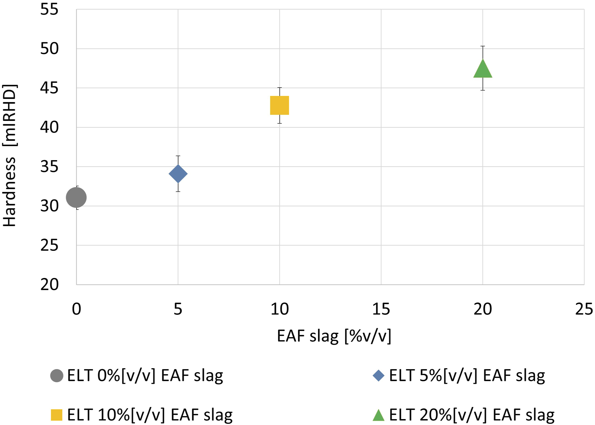
Tensile test
Figure 6 shows the stress-strain curves for a representative sample for each compound (ELT and ELT filled with 5, 10, and 20%v/v of EAF slag). It is possible to notice that with increasing the amount of EAF slag as filler both the stress and the strain at break decrease significantly beyond a slag content equal to 5%v/v. Stress-strain curves of EAF slag filled recycled ELT (ISO 37 type 2,
27
displacement rate 100 mm/min, room temperature).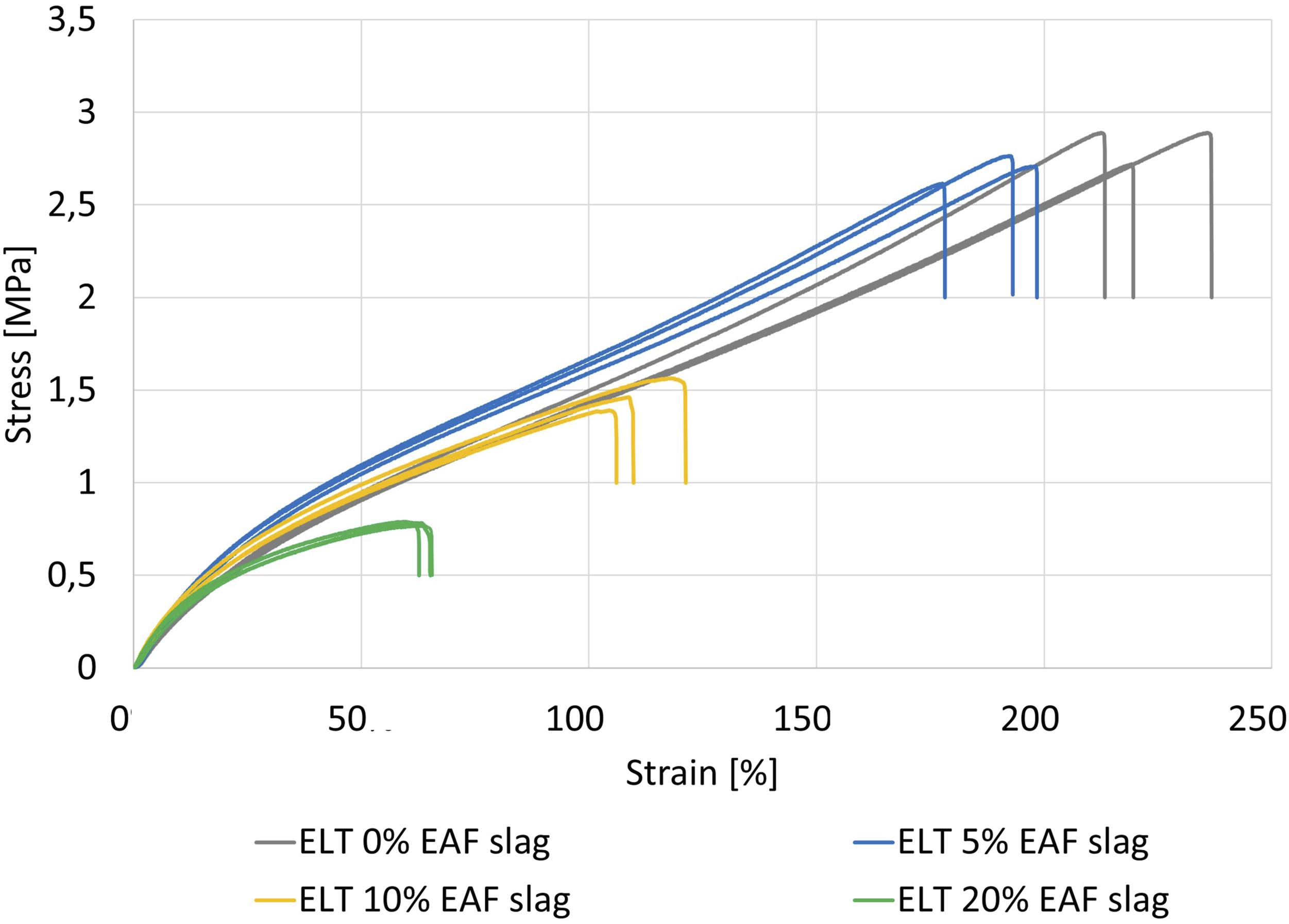
The presence of rigid filler in the elastomeric matrix limits the polymer mobility resulting in a reduction of the strain at break and in the generation of localized over stresses causing the lower stress at break. Thus, the strain hardening occurs only in the recycled ELT with no added slag.
The slag particles act a double role in the material: on one side, they promote the mechanical devulcanization during the calendering process by increasing the shear and the macromolecular network breakage; on the other side, they act as an obstacle to the mutual adhesion of the rubber particles. According to the tensile test results, it is possible to state that if a polymer fraction is adsorbed by the slag particles, this fraction is not sufficient to make the filler the load bearing fraction of the composite material but on the contrary, it weakens the ultimate tensile properties.
Figure 7 shows the elastic modulus calculated as the slope of the first linear section of the stress-strain curves. It is possible to observe that the presence of slag as filler slightly increases the composites modulus already for a content of 5%, then it remains about constant. This could be attributable to the double effect of the slag particles which, as aforementioned, promote devulcanization but also constitute the rigid phase of the material resulting in a global stiffening. Tensile elastic modulus of EAF slag filled recycled ELT.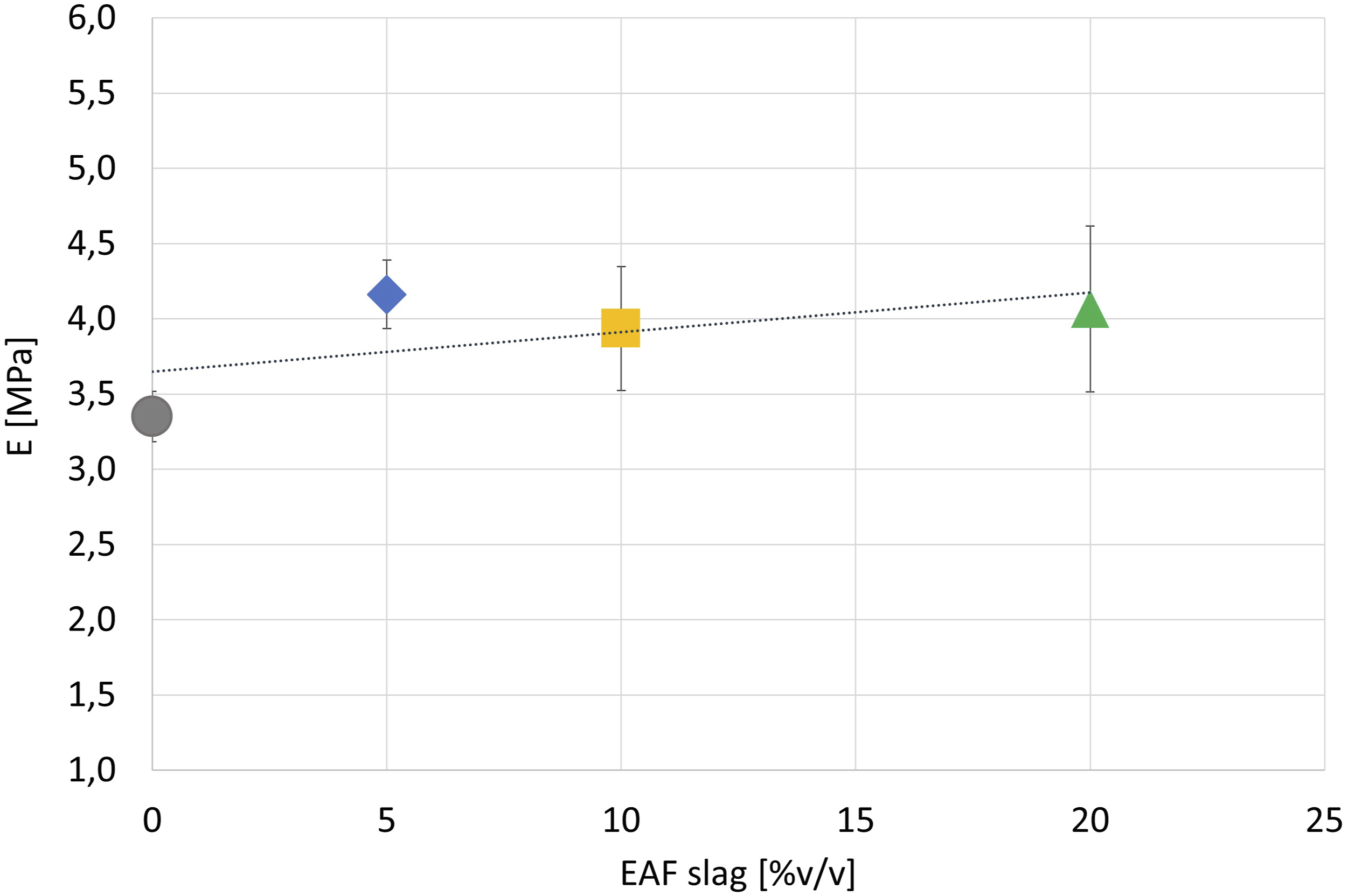
Scanning Electron Microscope analysis
Scanning Electron Microscope micrograph (reported in secondary electron image (left) and back-scattered electron image (right)) and backscattering images of cross sections of specimens tested in tensile test are reported in Figure 8. As first, it is possible to notice that the calendering process allows to obtain a compact and cohesive material; no discontinuities in the elastomeric matrix are visible although the presence of few micro crates. The good distribution of the slag particles can be appreciated from the SEM images in backscattering mode, while the micrographs collected with secondary electron probe give information on the fracture topography.
42
Filler particles detachment from the polymer matrix is observed for large particles, while the particles of small dimension seem to be well incorporated in the matrix with good filler-matrix interaction. SEM micrograph and backscattering images of cross sections of specimens tested in tensile test at different enlargements.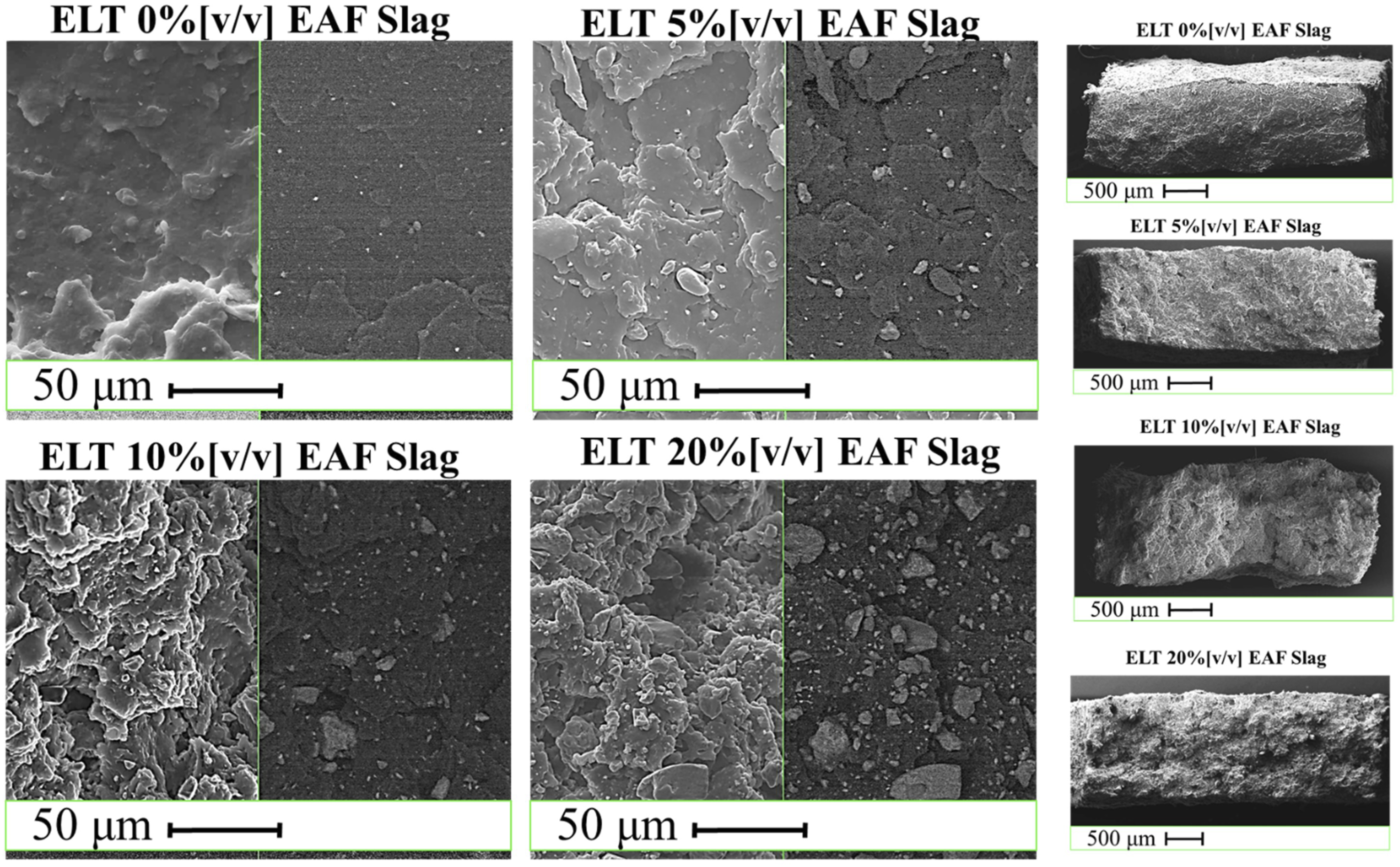
Mullins effect
As evidence of the good cohesion and uniformity of the material, in Figure 9 the Mullins effect is shown for the different composites. First of all, it is possible to state that the cyclic loading results in hysteresis which is already well visible at the second loading cycled up to reach a stable configuration at the third loading cycle. Uniaxial tension stress-strain cyclic loading at different strain (20, 30, 50%) of recycled ELT filled with EAF slag at 0, 5, 10, 20% v/v. Uniaxial static stress-strain curve is shown as dotted line.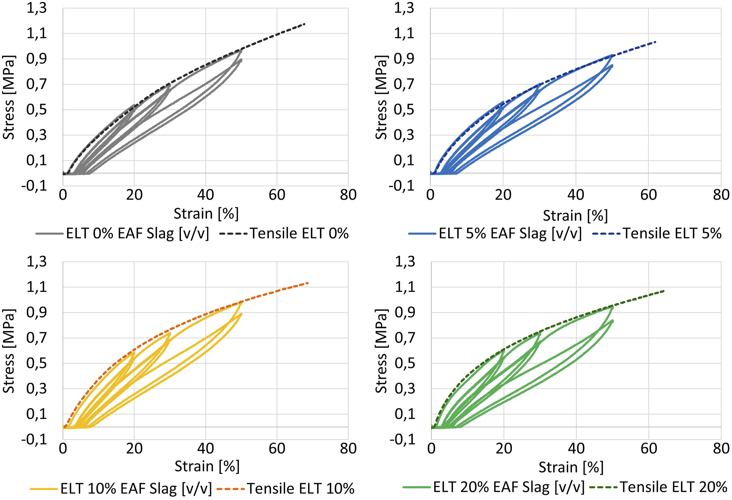
Moreover, when the applied strain exceeds that of the previous cycle, the stress returns on the same path of the uniaxial stress-strain curve, reported in Figure 9 as dotted line. This behavior is well known in filled rubber. 43
According to the literature, the physical explanation of the Mullins effect is related to several factors such as: bound rupture, molecules slipping on the filler surface (weak filler-matrix interaction due to low adsorption), filler aggregates rupture, and disentanglements and double-layer model (double-layer structure of bound rubber embedded in a crosslinked rubbery matrix).
Some researchers 43 attributed the Mullins effect to bond ruptures; particular attention was paid to the chain linking different filler particles that when completely extended breaks in correspondence of the particle surface.
Nevertheless, this model was confutated as it does not fit with the recovery of the imposed deformation at room temperature, because a bound rupture would involve a permanent set.
Therefore, Bueche and Houwink 43 proposed the slipping of polymer chains over the filler surface in the first loading cycle resulting on a change of the material entropy, which, however, could be restored apporting heat.
Hamed et al. 43 proposed the disentanglement model as responsible for the Mullins effect. The disentanglements caused by the imposed strain causes the stress-softening. In this configuration, the number of active chains is unaffected so that the recovery is possible by apporting heat due to the genesis of new entanglements.
For carbon black filled elastomers, Fukahori 43 proposed an interface model where the filler particles are surrounded by a immobilized polymer fraction in a glassy state which in turn is surrounded by a polymer layer constrained compared with bulk polymer. In the first loading cycle, this creates a network as it comes into contact with that of the adjacent particles. During the first discharge, this mesh persists and the bulk polymer compensates for the deformation. When the imposed strain exceeds that of the previous load cycle, the network structure returns to the previously extended state and supports the stress. Entropic forces in the network structure are believed to be the source of the recovery of the Mullins effect.
As shown in Figure 10, In the EAF slag filled ELT composites, it was found that up to 5% EAF slag content the dissipation is little affected by the imposed deformation (20, 30, and 50%) and remains at 15–18%; for 10% EAF slag, the dissipation increases and for 30% and 50% strain, it increases up to a value of about 23% while for 20% strain it remains at 18%; as last, for 20% of slag content the dissipation increases with increasing the imposed deformation at 28%, 24%, and 19% for 50%, 30%, and 20%, respectively. Mullins effect as energy dissipation [%] between the first and the fourth loading cycle for different imposed strain.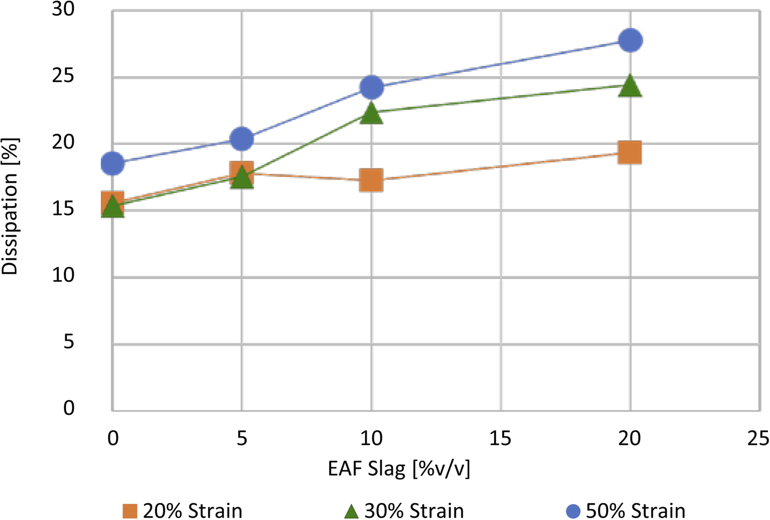
Magnetic properties
Electric arc furnace slag confers the composites magnetic properties due to the presence of trapped steel drops. The load required to detach a magnet form a slag filled ELT sample is shown in Figure 11. It was found that with increasing the slag content the detachment load increases. End-of-life tire 0%v/v EAF slag shows a small detachment load probably attributable to some metallic residue in the ELT powder. Detachment load between a magnet and the ELT samples filled with 0, 5, 10, and 20% v/v EAF slag.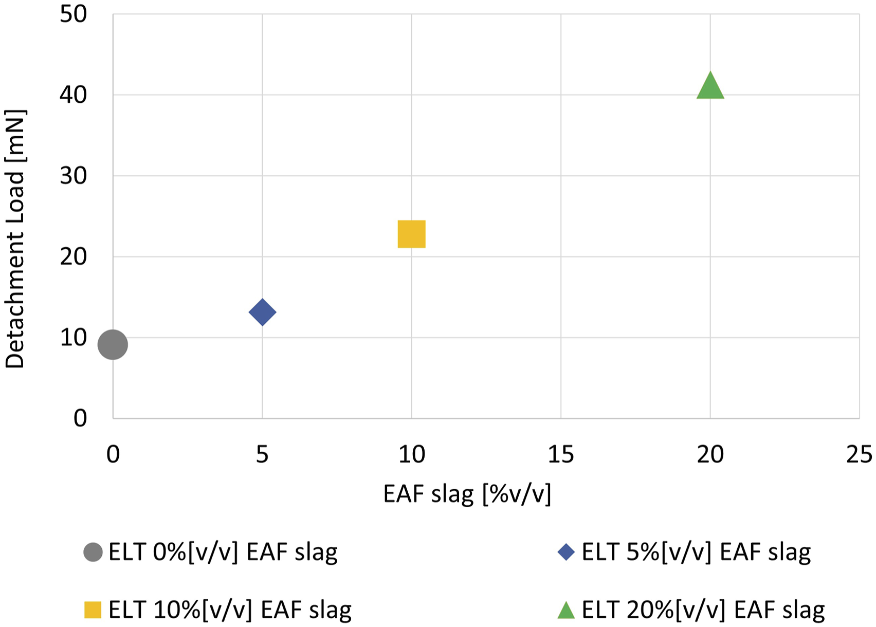
Electric arc furnace slag confers to rubber ferromagnetic properties, so it may be used as a shield for magnetic fields. Ferromagnetic materials with greater magnetic permeability than air provide a preferential path to the magnetic field. In this way, they absorb the flux lines of the magnetic field from the area around the source to be shielded. This application requires a specific characterization of the material.
Swelling
The swelling behavior of cured rubber indicates the crosslinking density of the material. This property is particularly relevant for rubber recycling, since on the one hand the crosslinking density affects the mechanical properties of the material and on the other hand crosslinks are responsible for the rubber curing, that is, or the impossibility of further processing it by means of heating the material as thermoplastic polymers.
The crosslink density is an important parameter in the rubber design of virgin cured rubber because the mechanical properties (hardness, tensile strength, elastic modulus) are strongly related to it. These properties strongly depend on the structure of the network, such as its density and the type of crosslinking. 44
In the present study, the applied recycling method involved the calendering of rubber powder up to the obtaining of a homogeneous and cohesive material. The rubber powder is mechanically stretched by the application of a shear stress which leads to the occurrence of a mechanical devulcanization. The presence of rigid slag particles can have a double effect: on one side, it can promote the mechanical devulcanization because they reduce the space between the rotating cylinders further accentuating the rubber shear stretching; on the other side the rigid slag particles interact with the rubber creating a rigid polymeric layer that reduces the swelling.
Swelling test results are shown in Figure 12. Swelling coefficient (Equation (1)) is reported as dotted line, while the crosslink density determined by the Flory–Rehner equation (Equation (2)) is reported as solid line. Crosslink density determined by the Flory–Rehner equation (ν [mmol/cm3]) and swelling coefficient on swelling test data (48 h immersion in toluene and 24 h drying at 80°C).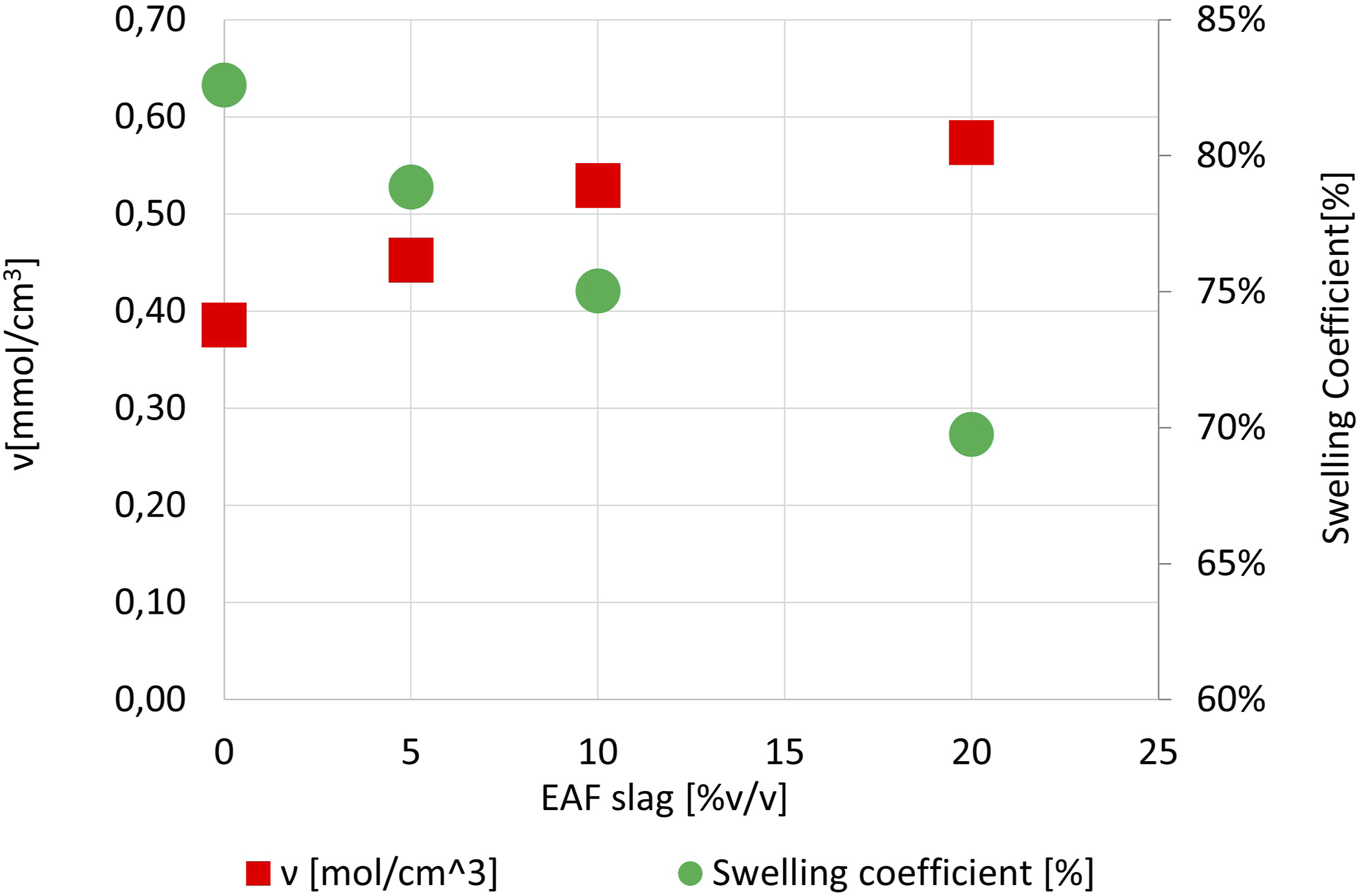
It was found that with increasing the EAF slag content the swelling coefficient decreases of about 10%, and the crosslink density slightly increases (Figure 12). These findings show that the presence of EAF slag as particles obstacles the solvent permeation. This could be attributable to the rigid polymeric layer around the slag particles and also to an increase in entanglements density. In the calendering process, the rubber powder became a network which is continuously stretched improving the physical bonds between the macromolecules.
Figure 13 shows the Kraus plot of EAF slag filled ELT in order to define the reinforcement (K) versus the filler volume fraction. The slope of the Kraus plot (K) is a measure of the polymer-filler interaction: the higher the negative slope value, the greater is the reinforcement effect. Vrf is assumed equal to Vr0 for ELT 0% EAF slag due to the purpose to evaluate the EAF slag influence neglecting that of carbon black which is constant for all the compounds. The negative slope of the Kraus plot denotes a reinforcement effect of EAF slag as filler for ELT. The coefficient of the negative slope was found equal to −0.57 Mondal et al.
34
found a Kraus plot slope of −0.64 for a NR/SBR bled filled with silica-graphene oxide, while a coefficient between 1.5 and 2.79 was found by Kim et al.
45
in NR compounds filled with different amounts of carbon black and accelerators. Kraus plot of ELT filled with 0, 5, 10, and 20% v/v EAF slag.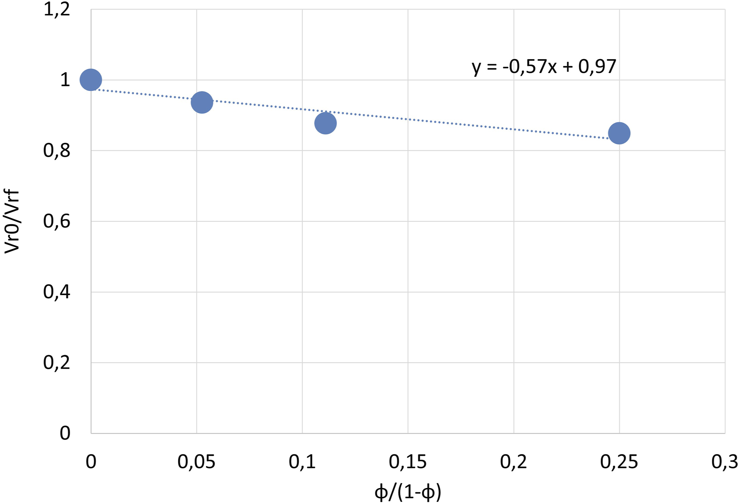
Differential scanning calorimetry
The increase in heat capacity net of the filler, ΔCp* is associated with the quantity of polymer that participates in the glass transition and depends on the polymer-filler interaction. Intermolecular rigidity is correlated to the polymer chains immobilized in the material: the rubber fraction immobilized was calculated according to equation (5); the results are shown in Figure 14. It is observable that as the EAF slag content increases, the increase in the heat capacity required by the rubber fraction at the glass transition temperature decreases due to the presence of a fraction of rigid rubber which remains in the glass phase even above the Tg. (a) Heat capacity scan determined by DSC at neat of filler versus temperature for EAF slag filled ELT. (b) Immobilized rubber fraction determined as the heat capacity increment at Tg ± 4°C.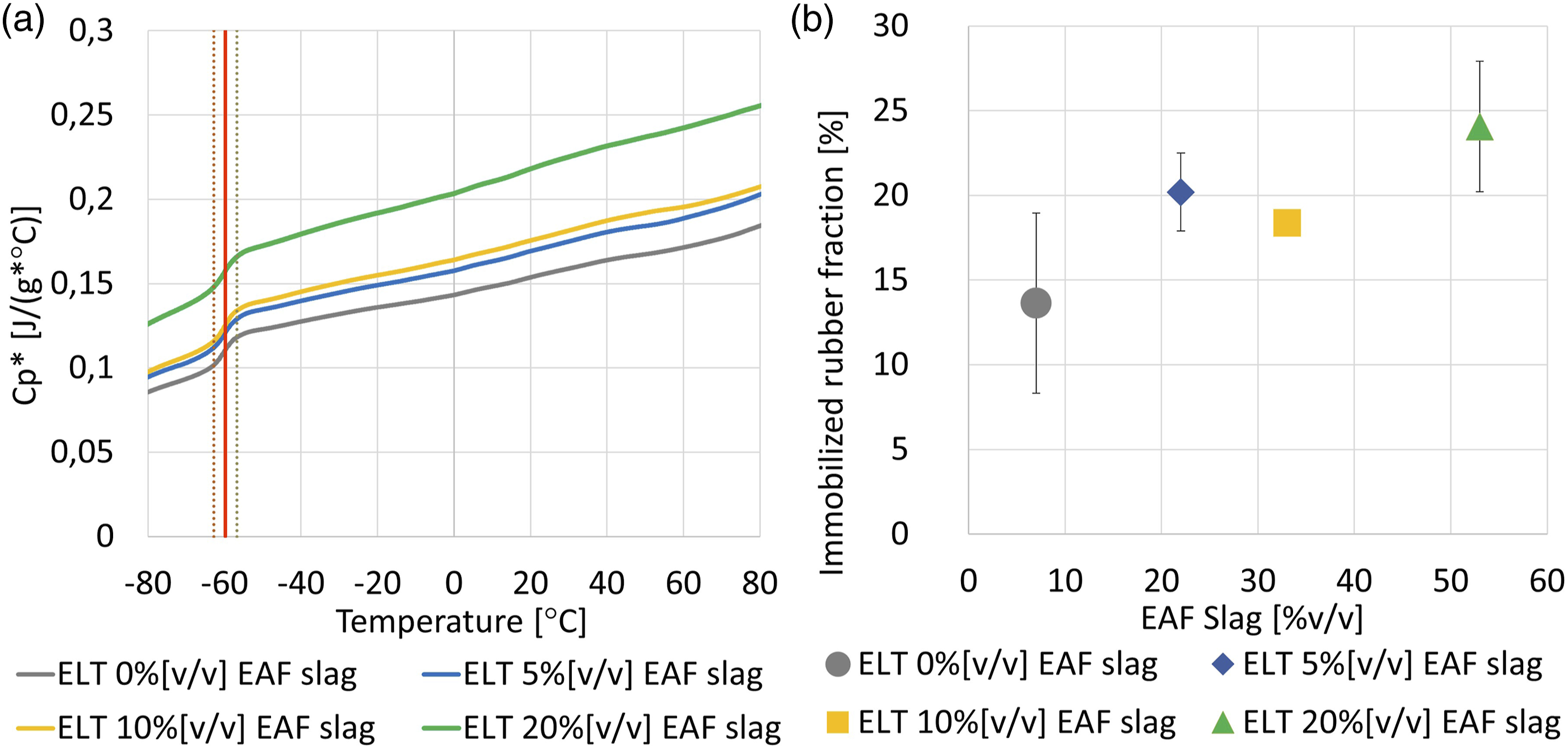
Tribological properties
Figure 15 shows the COF and specific wear rate (Ws) of ELT filled with 0, 5, 10, and 20% EAF slag [v/v] both in single-way and reciprocating wear configuration. Coefficient of friction (COF) and specific wear rate (Ws) of ELT filled with 0, 5, 10, and 20% EAF slag [v/v] in single-way wear and reciprocating configuration.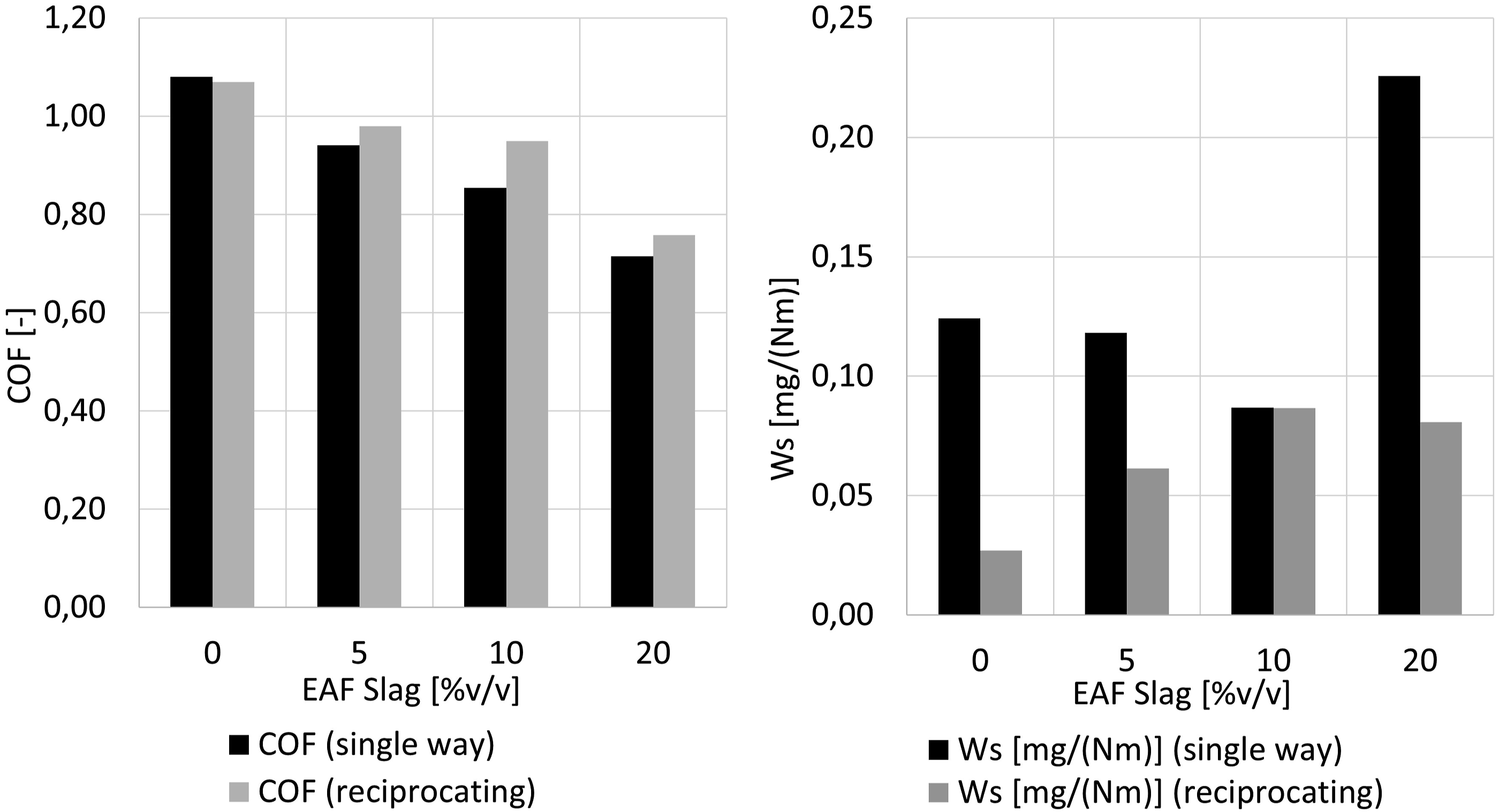
As regard the COF, it decreases with increasing the slag content in both wear configurations. On the other side, the specific wear rate in single-way configuration decreases up to a slag content of 10% [v/v] and then it dramatically increases for a slag content of 20% [v/v]. In reciprocating wear configuration, the specific wear rate increases with increasing the slag content up to 10% [v/v] and then it remains constant for a slag content of 20% [v/v]. The tribological mechanism underlying these results can be investigated by observing the wear tracks at SEM (Figure 16). BSE and EDS SEM observations of wear track of ELT filled with 0, 5, 10, and 20% EAF slag [v/v] in single-way and reciprocating wear configurations.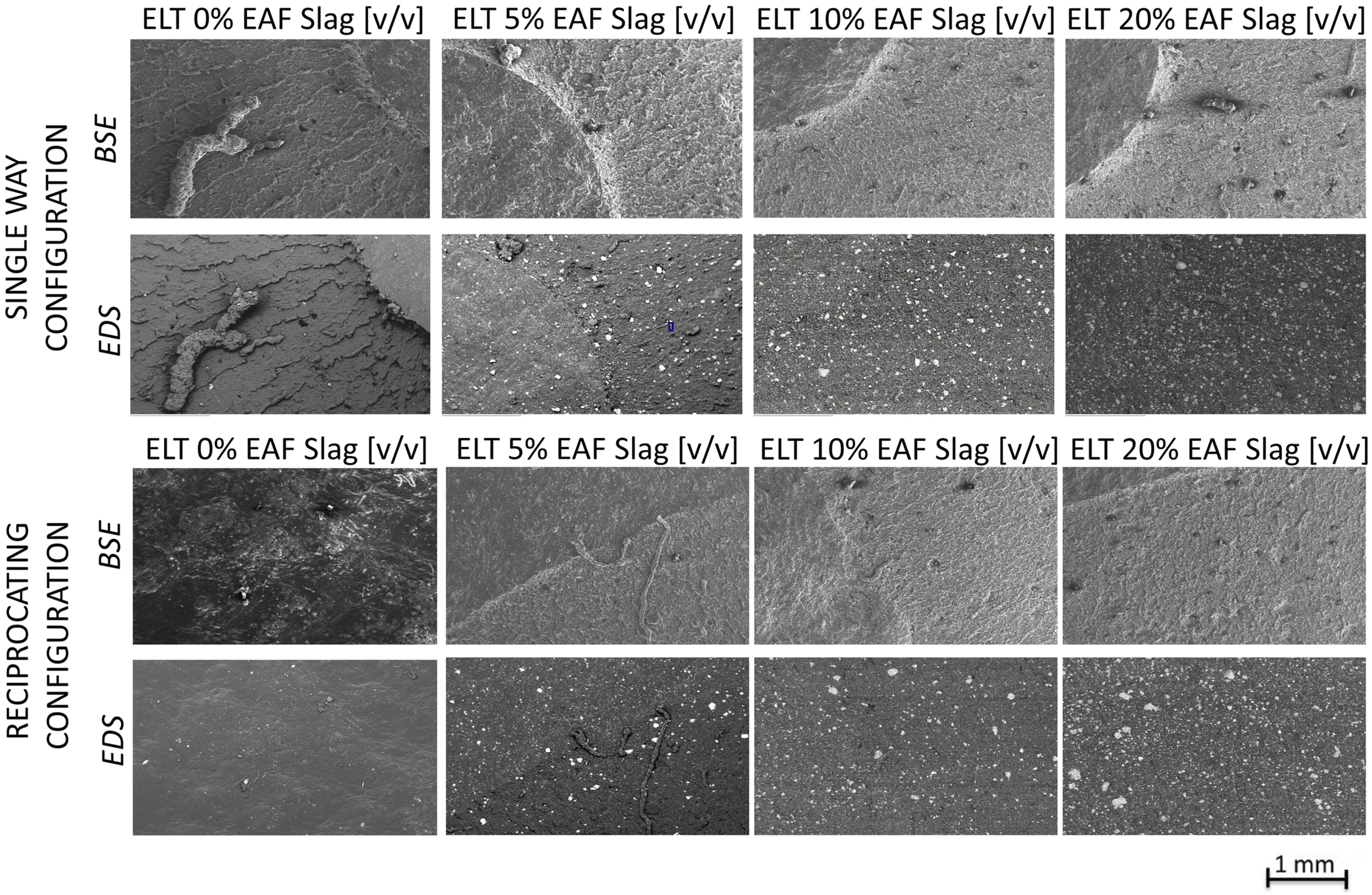
In single-way configuration the COF decrease with increasing the slag content can be attributable to a higher compound hardness which reduces both the hysteretic and adhesion effect. 46 This is evidenced by the formation of the Shallamach waves in the ELT 0% EAF slag (Figure 16). Regarding the specific wear rate of materials with a slag content up to 10% [v/v], it is possible to attribute its decrease to the formation of material rolls clearly visible to the SEM that remain on the track and protect the underlying material. This “protective” effect is more marked the greater the slag content that hardens the composite. For higher slag contents, we observe that in the material with 20% slag [v/v] the abrasive effect of the slag particles is preponderant. Probably this behavior is due to the triggering of a phenomenon of abrasive wear due rigid slag particles acting as a third body favoring the material asportation. It is interesting to note in the SEM images in BSD mode that the wear trace is clearly visible as the slag particles are better visible within the trace (they even seem to be present in greater quantities). This is because the rubber layer, which covers the filler, is gradually removed until the wear mechanism is able to remove also the slag particles. It is important to underline that the specific wear rate has been calculated on a mass variation of the sample, but the slag has a density almost 4 times higher than that of the rubber; therefore, the removal of a few particles of slag is equivalent to the removal of a large part of the rubber.
As regard the reciprocating wear configuration, the COF trend can be explained similarly to the test conducted in single-way configuration. The specific wear rate increase can be attributed to the formation of rolls kept on the track and protecting the underlying material. As the slag content increases, the abrasive phenomenon is a slightly more marked up to the achieving of a balancing of these two phenomena.
End-of-life tire filled with 10% [v/v] EAF slag can represent a good compromise between COF and specific wear rate.
Thermal conductivity
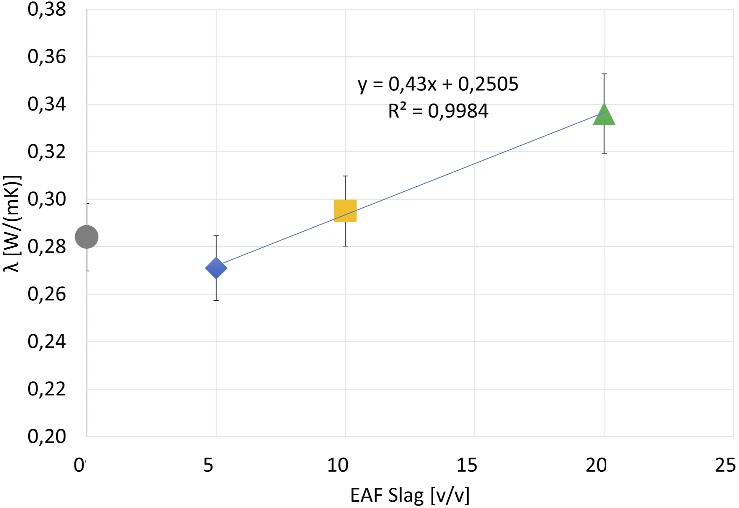
As shown in Figure 17, the thermal conductivity of the ELT samples with 5, 10, and 20% slag follows a linear increase (y = 0.43 × + 0.2505, R2 of 99.84%). The sample ELT 0% slag deviates from this trend, as in contrast to the expected lowest thermal conductivity, the measurement yielded to 0.284 W/mK. Based on the linear regression, Thermal conductivity (λ) of ELT filled with 0, 5, 10, and 20% EAF slag [v/v] determined according to ASTM E1530.
37
Conclusion
The present study shows the characterization of recycled ELTs filled with the main waste of the steel industry, namely, the steel slag, applying a very simple technology, at room temperature and without additives: calendering in an open mixer. Electric arc furnace steel slag has been evaluated as filler for recycled ELTs. The obtained results can be summarized as follows: • The incorporation of the slag into the recycled ELT matrix reduces the leaching of Cr, Mo, and V as well as the pH and electrical conductivity of the eluate revealing a safe new application of steel slag • The hardness of the composite increases as the presence of slag increases while the modulus of elasticity does not undergo evident variations. • The recycling process leads to a homogeneous and cohesive material as observed by SEM fracture surfaces. Furthermore, viscoelastic effects such as the Mullins effect are appreciable, in particular the dissipation increases as the slag content increases. This can be attributed to the interaction between filler and matrix. These results attest the achievement of an efficient recycling method. • The interaction between filler and matrix was also highlighted by the DSC data (increase in the fraction of immobilized polymer with increasing filler content and by the increasing in the crosslinking density). • From the tribological tests, it emerged that the COF decreases as the slag increases, while the specific wear rate decreases in the single-way wear configuration and increases (up to 10% of slag) in reciprocating wear configuration. • Finally, the slag gives the rubber magnetic properties and increases its thermal conductivity, expanding the possible applications of this 100% recycled material.
In conclusion, experimental results showed how some properties of recycled ELT can be improved without the exploitation of raw materials, enhancing not only the ELT but also the EAF slag in a context of circular economy.
Highlights
Characterization of recycled end-of-life rubber tire filled with black slag
• New product: steel slag as filler for recycled end-of-life rubber tires. • Recycled materials are homogeneous and cohesive: viscoelastic effects are evident. • Experimental results demonstrate the presence of rubber-EAF slag interaction. • Coefficient of friction decreases as the slag increases. • Slag gives the rubber magnetic properties and increases its thermal conductivity.
Footnotes
Acknowledgments
The authors thank GesTyre SCRL (Brescia) and Asonext Spa (Brescia) for providing the materials and test equipment and Lombardy region for the scholarship of AG.
Declaration of conflicting interests
The author(s) declared no potential conflicts of interest with respect to the research, authorship, and/or publication of this article.
Funding
The author(s) received no financial support for the research, authorship, and/or publication of this article.
Contributorship
Concept development (provided idea for the research), G.R., G.C.
Design (planned the methods to generate the results), G.R., G.C., A.G.
Supervision (provided oversight, responsible for organization and implementation), G.R., G.C.
Data collection/processing (responsible for experiments, patient management, organization, or reporting data), A.G.
Analysis/interpretation (responsible for statistical analysis, evaluation, and presentation of the results), A.G, G.R., G.C., C.P., R.C.K.
Literature search (performed the literature search), A.G.
Writing (responsible for writing a substantive part of the manuscript), A.G.
Critical review (revised manuscript for intellectual content, this does not relate to spelling and grammar checking), G.R., G.C., C.P., R.C.K.
Other (list other specific novel contributions), No other