
Abstract
Tufting has been shown to improve the mechanical properties of composites. Unlike other published works which rely on commercially available materials, for this study, continuous polymer yarns with diameters ranging from 160 μm to 720 μm of unfilled PPSU and PPSU nanocomposites with 1 wt.% of carbon nanotubes (CNT) were prepared using a twin-screw extruder. The tensile properties of these yarns generally improved with the addition of CNT at higher values of ‘screw speed to haul-off’ ratio. This effect is correlated with the yarn draw down ratio and attributed to the nanofiller orientation induced in the thermoplastic matrix. The fibres exhibited as much as a 23% increase in Ultimate Tensile Strength (UTS) for the same parameter set when loaded with CNT. Depending on filler and processing parameters set, yarns varied in UTS from 96.4 MPa to 206.2 MPa for unfilled PPSU and PPSU-CNT, respectively.
Introduction
Carbon fibre (CF) reinforced polymer composites offer significant improvement in material strength-to-weight ratio, when compared with materials traditionally used in aerospace and automotive industries. 1 Structural discontinuities in the form of fastener holes within structural aerospace components are a particular concern due to the associated stress concentration within an anisotropic material system.2,3 However, delamination of composite structures is a considerable drawback that can be potentially solved by a through-plane tufting of CF fabrics followed by resin impregnation step. This method of improving resistance to the delamination requires identification of a suitable tufting yarn material and optimal yarn characteristics.
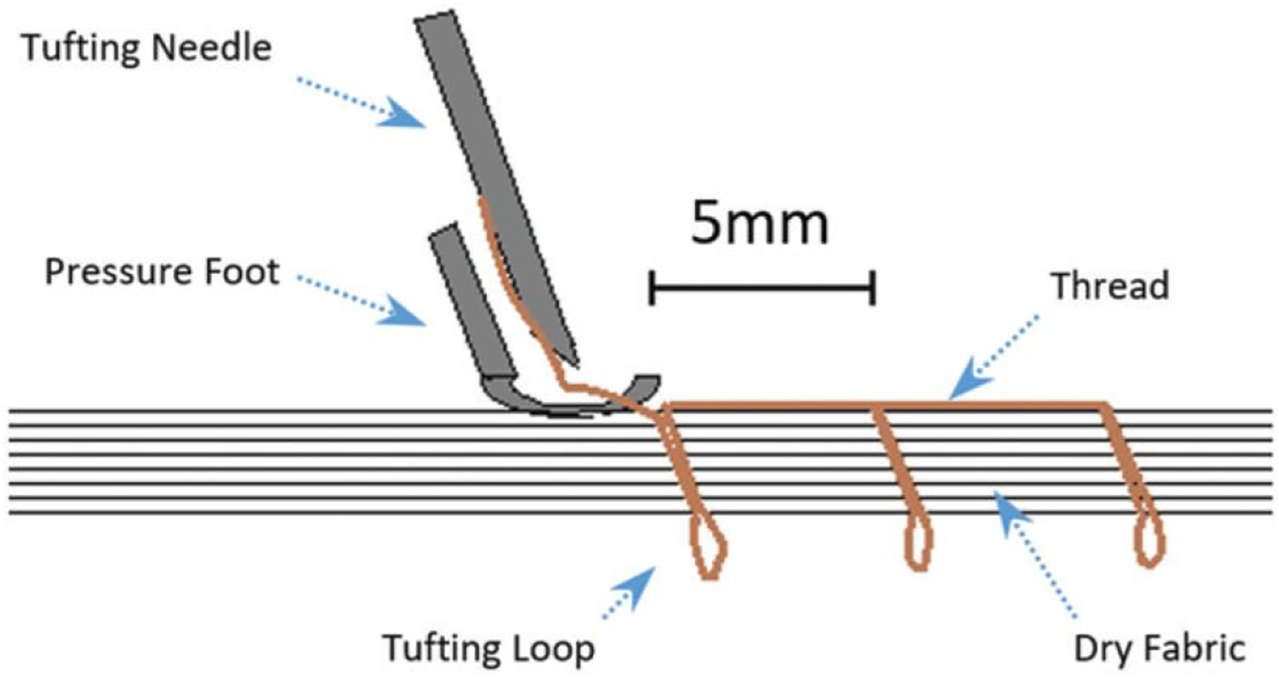
Tufting is a single-sided stitching technique that involves the insertion of a yarn through a fabric, in the z-direction. Its basic operation can be seen in Figure 1. Tufting arrests the displacement caused by crack opening displacement in mode I loading and crack sliding in mode II. The tufting thread functions as a pin, retaining the adjacent laminate regions following the transit of a delamination crack front through said region.
4
This provides reinforcement in both the site of the insertion of the tufting yarn and between the tufts.5,6 Tufting process for insertion of PPSU tufting yarns.
16
One method for the production of through-thickness tufted textile preforms is the insertion of a continuous CF, with an UTS of around 3000 MPa, into the preform. The mechanical manipulation of the carbon thread during the insertion process can result in a negative influence on the crack bridging properties of the yarn. 7
Other commercially available materials, such as polyparaphenylene terephthalamide (Kevlar®), have been used in the literature as tufting yarns. When exposed to mositure, Kevlar® can suffer a reduction in tensile strength of up to 22.4%.8,9 When knotted, Kevlar® has a reduction in its tensile strength suggesting it may not be an optimal material for use as a tufting yarn. 10 Mouritz and Jain have shown that a 0.39 cm2 stitch density of 70 denier polyester provided a greater resistance to mode I delamination when stitched into a composite than a 195 denier Kevlar® stitched into a composite at a stitch density 1.22 stitches/cm2. This is of particular interest as Kevlar® has a tensile strength of 238 cN/Tex, whereas polyester only exhibits 53 cN/Tex.11–13 Current literature seems to focus on the optimization of the tufting process parameters as opposed to the manufacture of an optimal tufting yarn.
Preliminary testing has shown that polyphenylsulfone (PPSU) is a potential candidate for such a tufting yarn due to its excellent mechanical and physical properties which can be further modified by the control of processing conditions and the addition of nanofillers. 14 In particular, CNTs have shown great success with increasing the mechanical properties of polymers even at extremely low percentage volumes. 15
Experimental
Material preparation
R-5500-NT PPSU pellets of ≈3 mm from Solvay Advanced Polymers, with a density of 1.29 g/cm3 and a Tg of 220°C, were placed into a vessel with liquid nitrogen for 5 min. This was to make them more brittle before being fed into a Fritsch Pulverisette 14 rotor mill, rotating at 15,000 r/min. Prior to the mixing with nanomaterials/extrusions, the milled PPSU was dried in an oven at 150°C for a period of 2 h to expel any moisture within the material. Nanocyl NC7000 multi-walled carbon nanotubes (MWCNTs) industrial grade (95% pure), with average fibre diameter 9.5 nm and average length 1.5 μm (aspect ratio c.a. 160), were homogeneously mixed in a charge bag with the milled PPSU in order to give 1.0 wt.% volume of MWCNTs to PPSU.
Extrusion
Extrusion parameters for production of PPSU yarns.
Fibre analysis
A SZ-PT Olympus optical microscope was used to examine the shape and surface topography of the particles before and after milling. Image-J software was then used to take average sizing measurements from each pellet/particle. A JEOL JSM-IT100 InTouchScope SEM™ was used for the SEM imaging. The fibre samples were cut into sections of 2 cm and these were placed into an Emitech K500x sputter coater and the vacuum was set at 8 * 10−2 mbars of pressure for 2 min and 30 s at 3 milliamps (mA). The fibres were then turned over and the process repeated. The coated samples were mounted on stubs and placed into the SEM 10 kV at a magnification of *45 was employed giving a clear image of the surface topography of the fibres while still allowing enough of a field of view to perform diameter analysis on the fibres. The measure function within the SEM was exercised 5 times on each fibre sample, measuring the diameter at 500 μm intervals.
Tufting
A KSL 522 tufting head mounted on a KUKA 125/3 robot operated with a KCP2 controller was used for all of the tufting. A modified KL 125 Groz-Beckert needle was fitted to the tufting head. The needles were modified by removing their exterior ridge, which is designed to spread the material being tufted, and by smoothing the eyelet with Mitchell’s abrasive chord. The basic tufting operation is shown in Figure 1 below.
A linear speed of 15 mm/s was used and the distance between the stitching along the seam, the stitching pitch (Lp), was set at 5 mm. Each of the thermoplastic yarns were tufted into a 400 mm × 200 mm layup comprising of 8-layers of 0/90, 285 g/m2 5 harness satin CF from Toho Tenax HS 6k. The tuft loops were kept as short as possible to reduce the risk of overlapping during compaction within the infusion stage as this would result in the formation of a resin-rich layer on the outer edge of the composite. 17
Composite manufacture
The tufted preforms were infused with Cytec (Solvay) Cycom 890 resin system and cured in a pressurized autoclave at 180°C for 2 h.
Material testing
An Instron 3344 tensile testing machine, equipped with a 500N load cell and Series 2710-200 Screw Action Grips, was employed throughout the fibre tensile testing. ASTM D3039/D3039M-15 ‘Standard Test Method for Tensile Properties of Polymer Matrix Composite Materials’ and ASTM D3217-07 ‘Breaking Tenacity of Manufactured Textile Fibres in Loop Configurations’ were followed for the tensile testing. Paper tabs were bonded to either end of the polymer yarns, with SP106 resin, to avoid the grips causing damage to the fibres. The gauge length between the grips in this case was set to 1 inch (25.4 mm). The samples were tested at a constant speed of 20 mm/min until failure.
Glass-fibre reinforced polymer tabs were bonded to either end of the tensile specimens to prevent damage to the test specimens during gripping. The open-hole tension tests were performed in accordance with ASTM D5766/D5766 M – 11 ‘Open-Hole Tensile Strength of Polymer Matrix Composite Laminates’. 18 A central pilot hole was drilled though each sample prior to being reamed with a ¼ inch EDP 4204 one shot drill reamer from Mohawk specifically designed to eliminate the possible delamination upon both entry and exit of the reamer. One side of each specimen was prepared for digital image correlation (DIC) by means of the application of a speckle pattern. 2-axis strain gauges from Tokyo Sokki Kenkyujo Co Ltd (TML) were bonded to each sample on the alternate side. These were connected to the National Instruments DAQ in order to measure strain. The samples were subsequently loaded in the warp direction into an Instron 5500R tensile tester with the gauge length set to 150 mm. A constant cross-head speed of 2 mm/min was used for all of the tensile testing and a 50% drop in load set as the test termination condition.
Results and discussion
The average diameter of polymer pellet was reduced by 90.4% (3.5 mm) from 3.8 mm to 0.4 mm/in an attempt to both aid mixing with the CNTs and aid heat transfer to ensure a homogenous melt within the extrusion process.
19
This reduction was designed to produce a more geometrically consistent extruded yarn, while aiding the mixing of PPSU and nanomaterials.
20
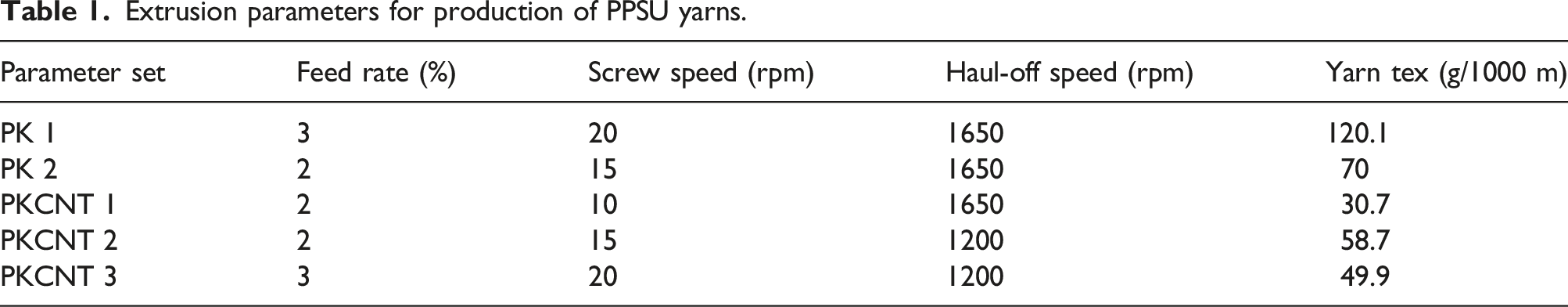
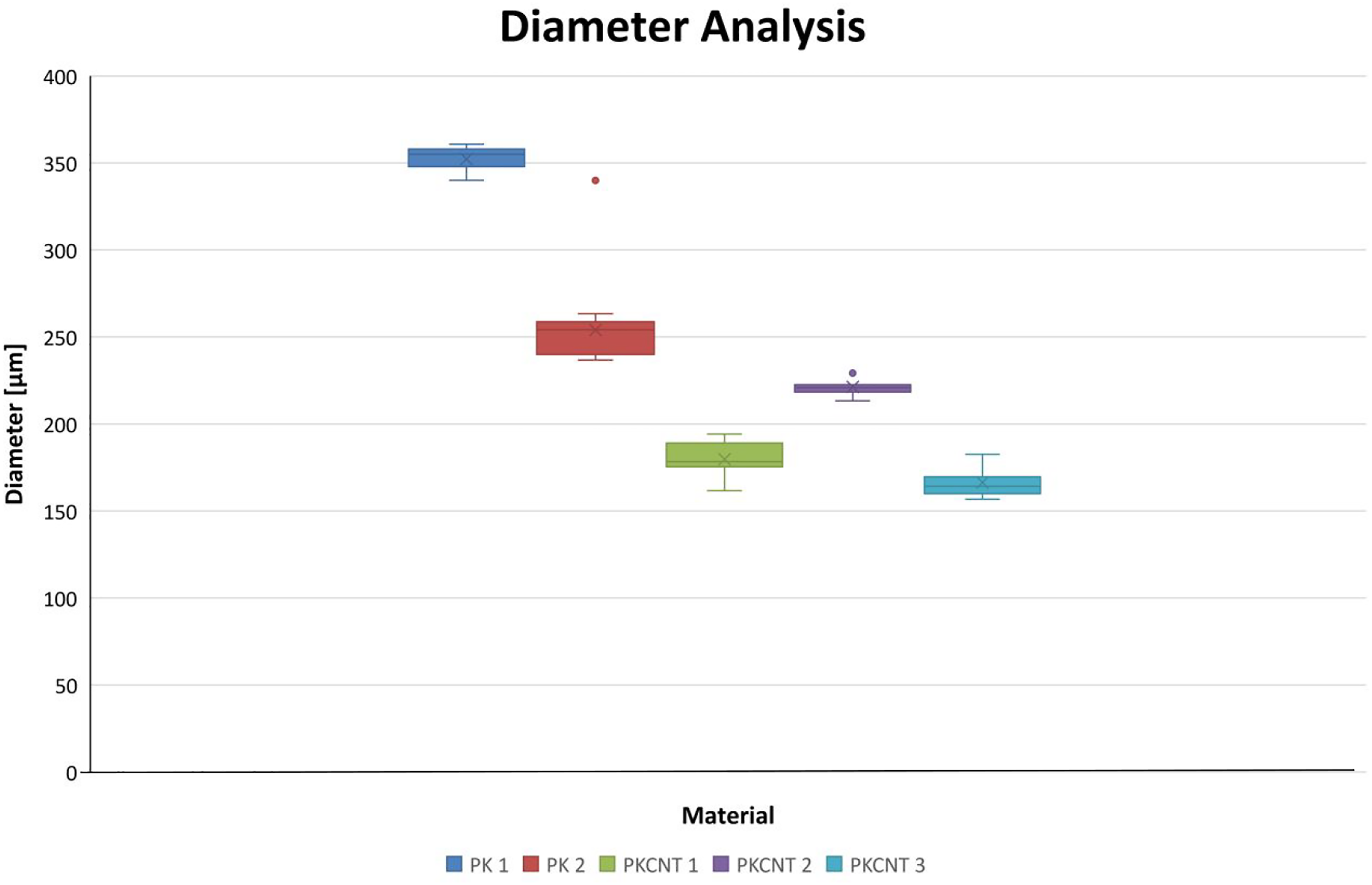
The increase in extrusion stability is evident from both the SEM images observed in Figure 2 below and also by the minute error bars in Figure 3 where yarn diameters at the varying processing conditions are shown. SEM micrographs at 20 kV and a magnification of ×120 of PK1 and PKCNT3 tufting yarns. Extruded PPSU yarn diameters from SEM analysis.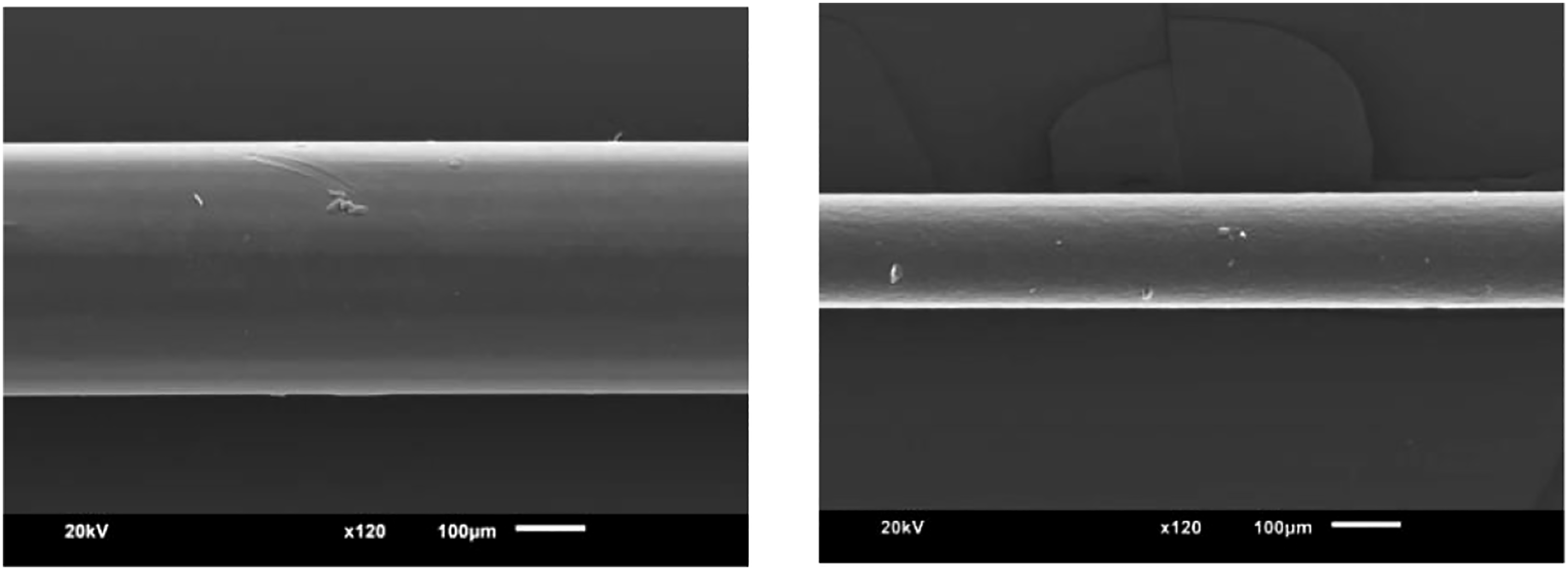
Previous work has shown that the reduction in diameter of a tufting yarn minimizes the previously seen fibre misalignment at the site of insertion of the tufting yarn into the composite, thus reducing the potential reduction in mechanical properties.16,21
Previous experimental work by Domenech et al. has shown that structuring of extruded nanocomposites can be optimized by working under higher specific mechanical energy (SME) until a critical limit is reached.
22
In this case, processing at a higher SME was limited by the maximum torque the machine was capable of achieving (Figure 4). SME from PPSU and CNT reinforced PPSU yarn extrusions.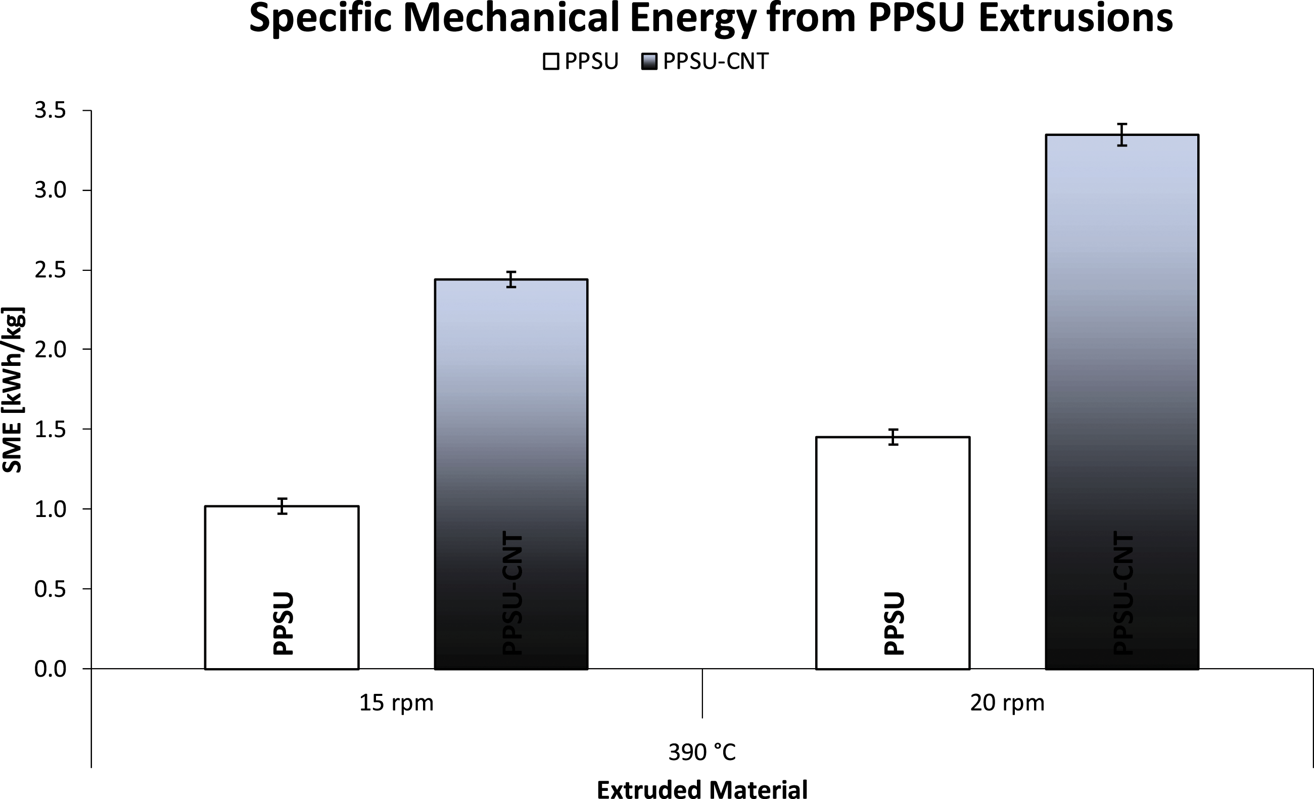
Figure 5 shows a TEM image of a section of one of the CNT reinforced PPSU tufting yarns. The darker items within the image appear to be CNT, matching the expected dimension and geometry of CNT from the literature.23–25 As individual CNTs are visible in Figure 6, this suggests that they are well dispersed with no agglomerates in the PPSU matrix. All the CNT reinforced PPSU polymers had a similar appearance and apparent dispersion. This corresponds with the increase in mechanical properties observed for the CNT filled PPSU yarns in Figure 6.
26
Transmission electron microscopy image of CNTs within PPSU tufting yarn at an accelerating voltage of 200 kV. Extruded PPSU tufting yarn straight fibre UTS.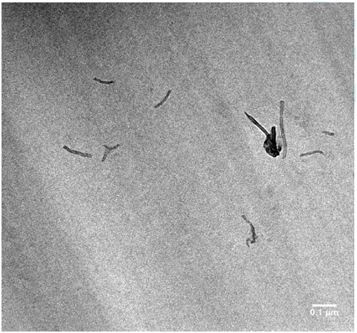
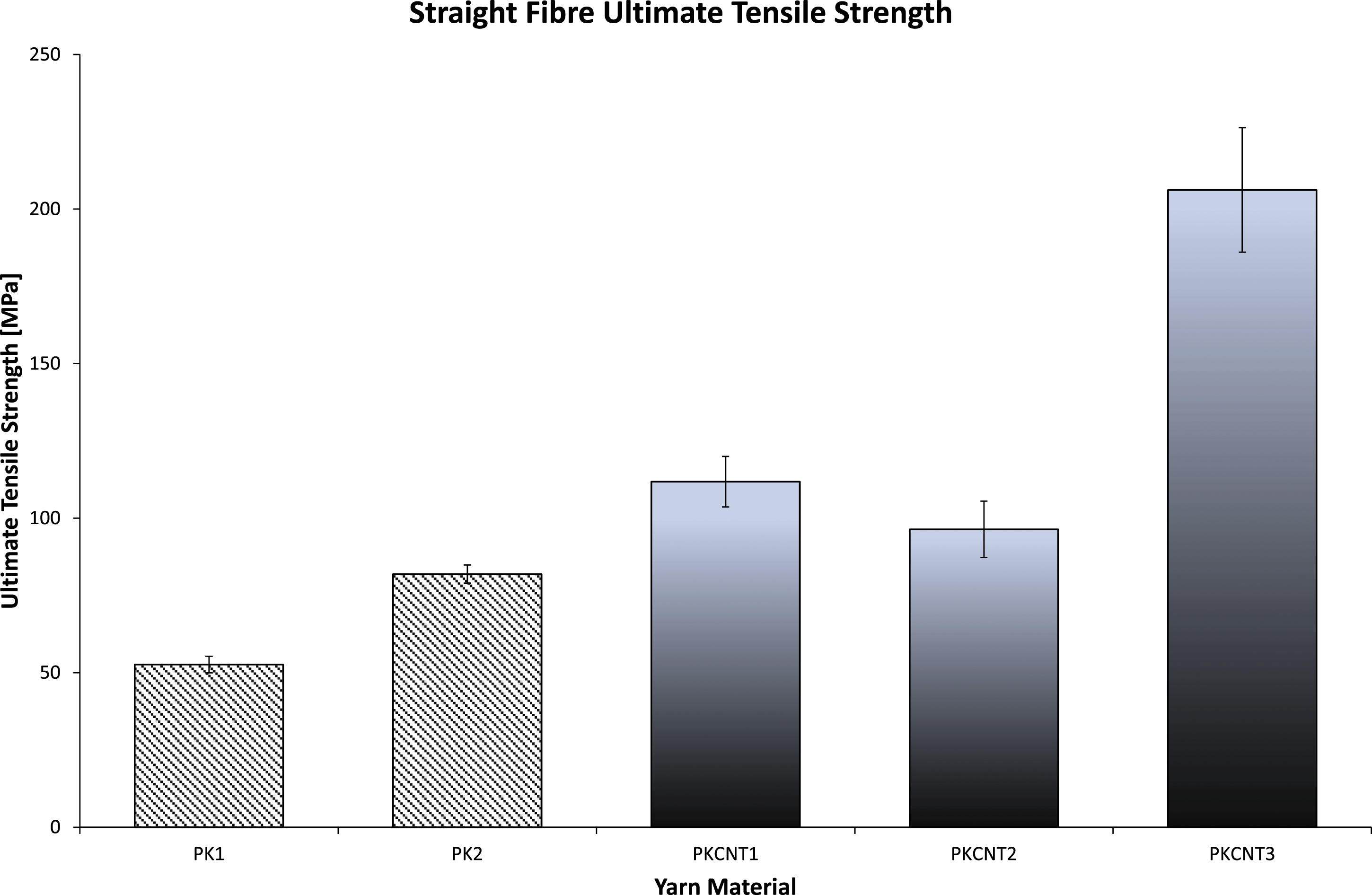
Tensile properties are shown to have been increased with CNT loading, as per Figure 6. The fibres were seen to have as much as a 23.31% increase in UTS for the same extrusion parameter set when loaded with CNTs. Depending on filler and processing parameters set, PPSU yarns varied in UTS from 96.4 MPa to 206.23 MPa as is evident below.
Extruded PPSU tufting yarn Young’s modulus.
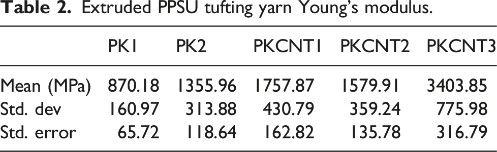
Modification of the extrusion parameters allowed for a 12.5% increase in UTS. As much as a 112.4% increase in UTS was observed with the addition of CNTs. Similar levels of improvements to polymer mechanical properties following the addition of carbon nanotube reinforcement, such as the 123.9% increase to UTS, were observed by De Zhang et al. with addition of 1 wt% MWCNTs to nylon-6. 27 The optimum parameter set used here appeared to be screw speed of 20 r/min and a pelletizer speed of 1200 r/min. Compared to the other CNT reinforced extrusion at 20 r/min, the increase in haul-off resulted in a 138.5% increase in straight tensile UTS. This could be partially attributed to both the increased alignment of the nanotubes, as a result of the increased haul-off speed and as a result of the increase in SME. 14
It is hypothesized that the loop strength of the polymer yarns will provide an insight into both their ability to survive the tufting process and their ability to provide reinforcement to the composite. Figure 7 below shows the UTS of the varying extruded PPSU tufting yarns. Due to the configuration of Extruded PPSU tufting yarn looped fibre UTS.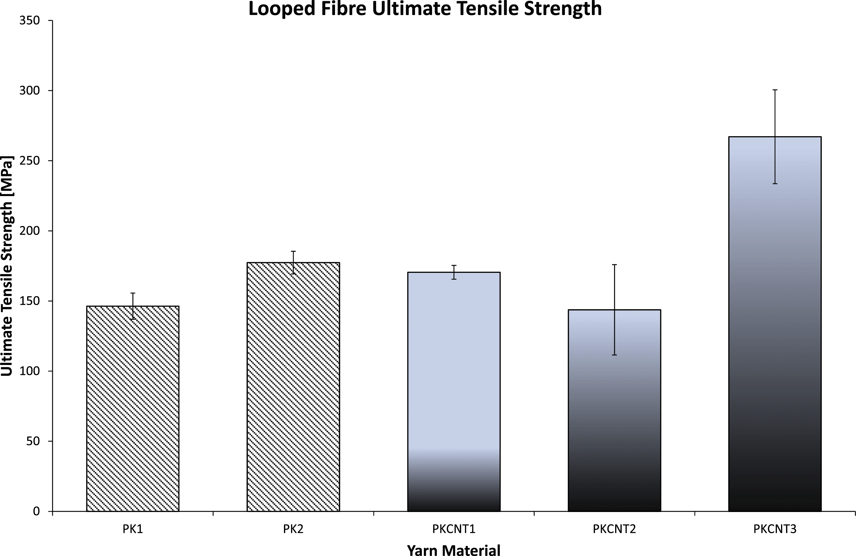
It is evident from both Figures 6 and 7 that a higher SME aids the increase of UTS of CNT reinforced PPSU.
Although no firm conclusion had previously been drawn regarding the influence of the mechanical properties of the polymer yarn on their ability to be tufted, it has been noted that the yarn with the lowest UTS in the straight configuration, the lowest yield strength in all 3 tensile configurations and the lowest Young’s modulus also happened to be the only yarn which posed difficulty being tufted into a composite.
All of the composites were ultrasonically scanned following infusion to check for significant manufacturing defects prior to testing. μCT has revealed that the introduction of the tufting yarns caused fibre spreading or fibre misalignment to accommodate the insertion of the tufting yarn, similar to that observed by Scott et al. tufted composites. This ‘eye’-shaped region has been shown to be the site of a resin-rich region within the composite.
6
(Figure 8) Tufting site of tufted composite μCT and tufting site of optical microscope image of internal cross-section.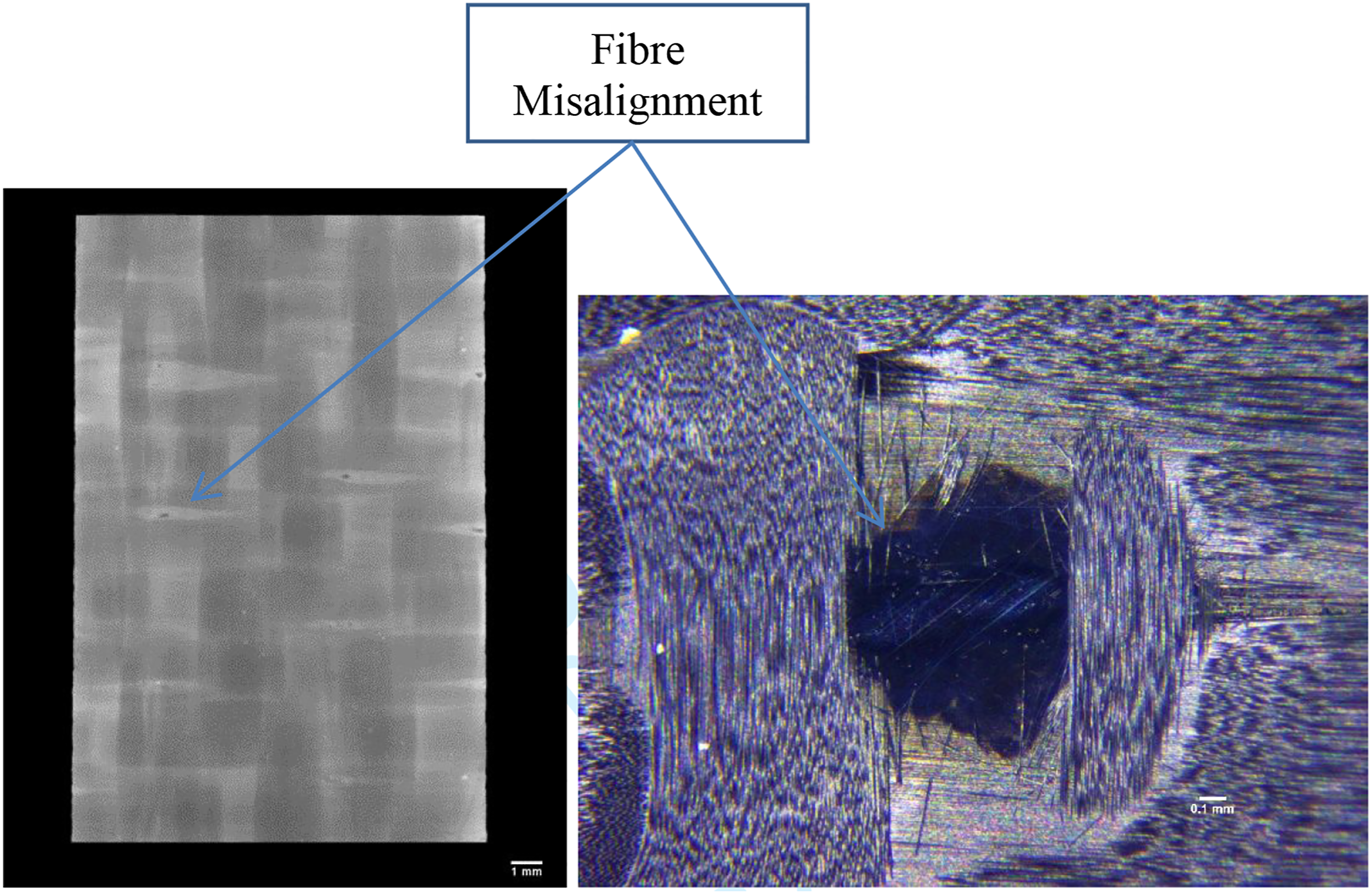
The calculated volume fraction results are as follows: Non-tufted 3.15 mm 51.41%Vf, PK1 3.6 mm thick 44.98%Vf, PK2 3.04 mm thick 53.27%Vf, PKCNT1 2.96 mm thick 54.71%Vf, PKCNT 2 3.03 mm thick 53.44%Vf and PKCNT3 2.97 mm 54.52%Vf. The introduction of the tufting yarns resulted in the expected increase in Vf which, according to Dell’Anno et al., is a result of the extra compression of the laminate during infusion. 28
The introduction of the PKCNT1 tufting yarn gave a 14.5% increase in UTS over a non-tufted composite in Figure 9 below. When compared to a PPSU tufted composite produced in preliminary work by the author, the PPSU yarn used below, PK1, gave an open-hole tension UTS of 1.3% greater than previously when tufted into a composite, despite a 12.5% increase in UTS of the yarn. This minute increase in tufted composite UTS is believed to be the result of extrusion processing improvements with the polymer. The reduction in diameter of the new PPSU yarns could also be contributing to this, with less misalignment occurring in the composite due to their smaller size. The PKCNT3 only offered a 9.7% increase in UTS despite having the highest yarn strength in both the straight and looped configuration. It is hypothesized that the CNTs in PKNT1 are aligned closer to the loading configuration experienced by the yarn within the tufted composite than those in the PKCNT3. Mirjalili and Huberts work suggested that CNTs can bridge crack growth fronts when they are aligned in the loading direction, thus giving the increased UTS.
29
The PK1 yarn resulted in a decrease in UTS for the open-hole tension. In this case, an 8.4% decrease was observed. The PK1 yarn also happened to have the lowest UTS, lowest yield strength and lowest Young’s Modulus of all the PPSU yarns tested in this study outside of the composite. It is hypothesized that the mechanical properties of the PK1 polymer yarn are below the minimum threshold mechanical properties for a mechanically beneficial through-thickness tufting yarn. PPSU tufted composite UTS comparison.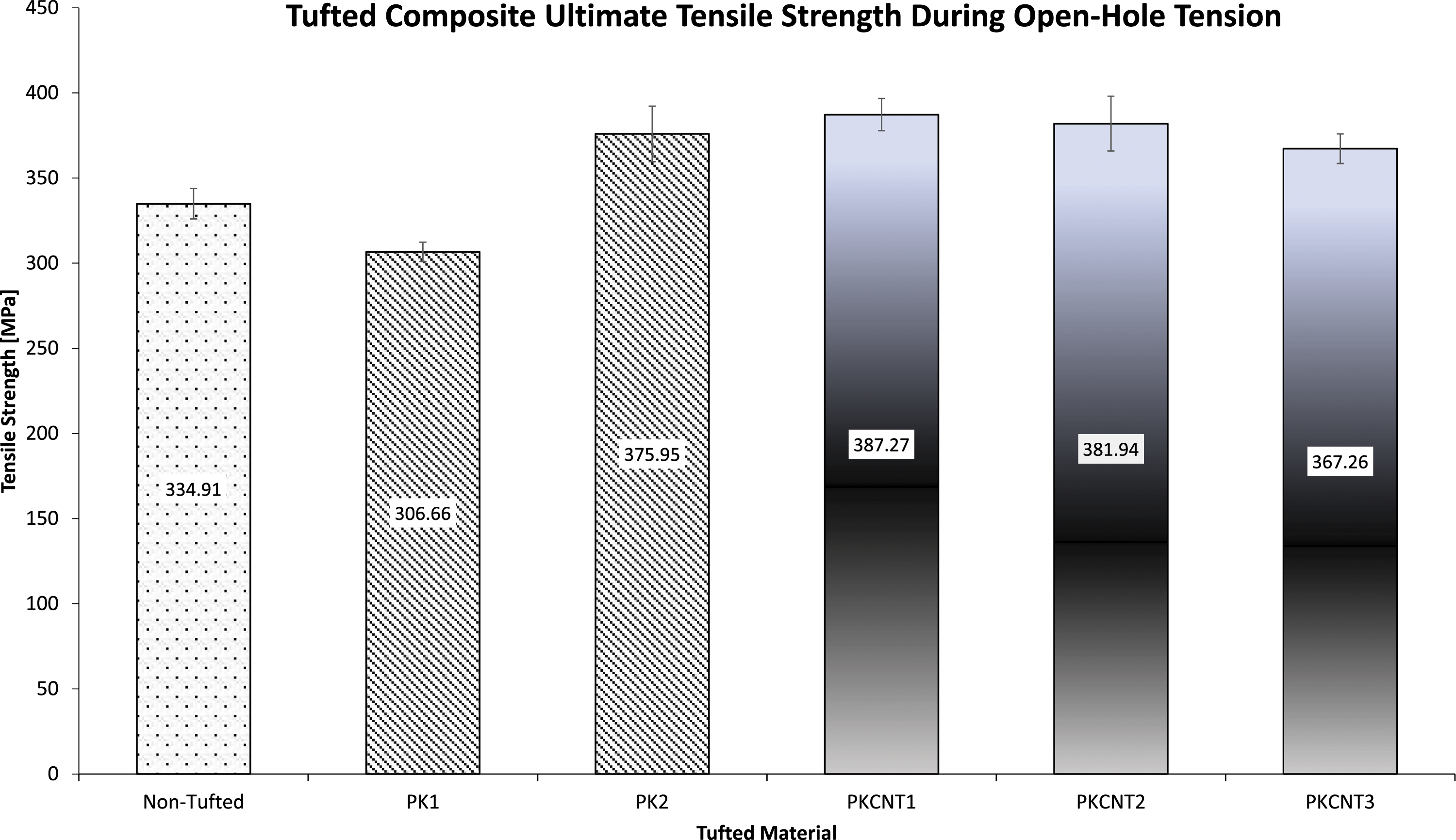
A positive correlation between the UTS of the fibres and the UTS of the composite has been observed for un-notched tensile testing in the author’s previous work. 16 However, during the open-hole tensile testing, the PKCNT3 did not provide the largest UTS despite its superior mechanical properties outside of the composite.
Karuppannan et al. demonstrated a 14.8% degradation in open-hole tensile strength following tufting a 3992 MPa UTS carbon thread, with a tensile modulus of 236 GPa, into a carbon composite. 30 Despite the UTS and Young’s Modulus of the PKCNT1 yarn being significantly lower than that of Karuppannan’s yarn, a 14.5% increase in open-hole tension strength was observed when the PKCNT1 was tufted. It is hypothesized that a specific range of UTS and Young’s modulus of the tufting yarn are required to result in an increase in the mechanical performance.
Young’s modulus of CFRP open-hole tension samples.
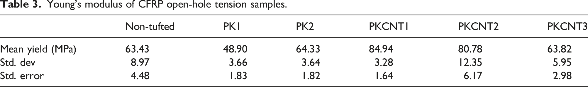
Zheng et al. show as much as a 10% increase in UTS of an open-hole tension sample of Kevlar stitched CF depending on stitching direction. The increase was observed when stitched at a 45° angle. 31 It is hypothesized that with further work in the placing of tufting yarns in this study, a much more significant increase in the open-hole tensile strengths could have been achieved.
Conclusion
Current works tend to focus on the tufting process parameters as opposed to the manufacture of a tailored tufting yarn. CNTs provided an increase in UTS of the PPSU tufting yarns under all tensile testing configurations. In both the straight fibre and looped fibre tensile tests, one particular extrusion parameter set for the CNT reinforced PPSU exceeded the UTS substantially: screw speed of 20 r/min and a pelletizer speed of 1200 r/min. This could be partially attributed to both the increased alignment of the nanotubes, as a result of both the increased haul-off speed and the increase in SME. A positive correlation between the UTS of the fibres and the UTS of the composite has been observed. It is postulated that these tufting yarns enhanced load transfer within the composite, as per their improvement in UTS. However, despite its superior mechanical properties outside of the composite, the PKCNT3 did not provided the largest UTS during open-hole tension when tufted into the composite.
It is hypothesized that there is a maximum and minimum UTS and Young’s modulus range of a tufting yarn that exists outside of which there are no improvements to mechanical performance of a composite once tufted.
Footnotes
Declaration of conflicting interests
The author(s) declared no potential conflicts of interest with respect to the research, authorship, and/or publication of this article.
Funding
The author(s) disclosed receipt of the following financial support for the research, authorship, and/or publication of this article: The author would like to thank Daniel Breen, Sam Wilson, Oran Walsh and Seamus Mc Garrigle for their assistance with the project. This work was carried out under EPSRC grant number EP/L02697X/1 and was part funded by the Department for Employment and Learning (Northern Ireland Executive).