
Abstract
A methodology is presented to implement robotic actuators into diaphragm forming of composite laminates. This Hybrid Vacuum-Robotic (HyVR) process is specifically targeted to prevent ‘bridging’ type defects. Examples are presented of successfully forming laminates with deep concave features that would otherwise be impossible by diaphragm forming. The robotically controlled end effectors apply localised pressure to concave regions during the diaphragm forming process. This force application is analogous to the incremental sheet forming process. A generalised methodology is presented which can be applied to develop a bespoke HyVR process for a specific mould. It can then inform what type of end effector should be used and how to apply it within the HyVR process. A key development included in this methodology is the use of the robot to ‘pin’ the laminate to the mould, preventing any unwanted movement. This process could enable automated production of more complex components using diaphragm forming, taking advantage of its lower tooling and equipment costs.
Introduction
Automated composite manufacturing processes can be categorised broadly into two approaches; those that build up the finished material by laying down fibres in the form of narrow unidirectional tapes, as reviewed by Lukaszewicz et al., 2012 1 or those that use broadgood sheet materials, as reviewed by De Zeeuw et al., 2020 2 and Elkington et al., 2017. 3 Tape based methods such as Automated Fibre Placement (AFP) can be effective for forming flat or simply curved shapes, but complex geometries featuring double curvature, tight radii and negative volumes may not be viable. These systems can also involve significant start-up costs, making them uneconomical to small or medium sized manufacturers.
For forming broadgood sheet materials, Diaphragm Forming (DF) and Press Forming are two of the most common automated manufacturing techniques. 4 Press or stamp forming involves a two-part male-female mould set which closes together to form the laminate. This can provide a good surface finish on both sides of the laminate, excellent thickness control and the potential of rapid cycle times. However, the stamping process requires the construction of two closely toleranced, hardwearing mould halves, alongside machinery capable of applying large closing forces. 5 This adds considerable start-up costs, making press forming uneconomical for short production runs and product prototyping. In addition, press forming typically uses blank holders around the perimeter of the moulds. This requires the laminate to extend beyond the outline of a finished component, wasting material and requiring an additional trimming operation. 6
Diaphragm forming (DF), more generally known as ‘Vacuum’ forming is an alternative to stamp forming which uses atmospheric pressure to drive the forming process. It is gaining popularity and is being promoted by Solvay S.A. as the ‘future of composites’. 7 A single sided mould is placed inside an open topped chamber with a flexible diaphragm sealed around its upper periphery. Double diaphragm forming (DDF), a specific type of DF, employs a secondary flexible membrane between which the laminate is encapsulated. The chamber below the diaphragm is then evacuated and atmospheric pressure pushes the diaphragm downwards, forming the laminate onto the mould surface. Under optimum conditions, this process can provide a rapid and robust manufacturing method ideal for volumes on the order of 30,000 units per annum. Capital investment is restricted to a single sided, low cost mould, a vacuum pump and standard off-the-shelf consumables. 8
The ‘bridging’ defect during forming
A main issues restricting DF from widespread use is ‘bridging’, where the laminate fails to conform to concave mould features.
9
An example of using DF to form this type of geometry is presented by Alshahrani et al., 2017
5
and shown in Figure 1. It can be seen that the laminate failed to conform to the concave curvature of the mould, potentially causing major structural and aesthetic problems in the finished component. Example of a ‘bridging’ defect formed across a concave curvature on the mould during diaphragm forming.
5
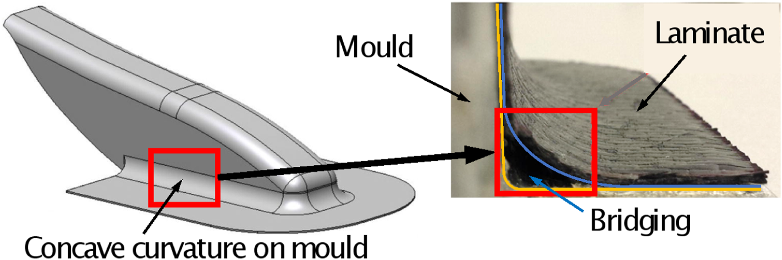
Forming of reinforced laminates from a flat sheet into a three-dimensional shape is a complex process, requiring a range of forces to be overcome. The reinforcing fibres themselves have a bending stiffness, but for dry, unimpregnated fabric, this stiffness is significantly lower than in-plane stiffness because interlaminar slipping can occur with little resistance. 10 However, once a reinforcing polymer is impregnated into the material, either an uncured thermoset resin or a heated thermoplastic resin, the laminate will have significant interlaminar shear stiffness and therefore out-of-plane bending stiffness.11,12 When forming double curvature mould shapes there is the additional factor of in-plane shear, the resistance to which is also dominated by the properties of the reinforcing polymer.5,13 As well as resisting forming, this interlamina stiffness can generate compressive forces in plies located at the inner radius, resulting in wrinkling.10,13,14
In addition to the internal material resistance, there is a significant amount of friction to overcome during the forming process. The links between excessive friction and bridging defects are well understood and are illustrated in Figure 2, based on the explanation by Chen et al.,
6
2017. In the initial stage of forming (Figure 2(a)), the main resistance against atmospheric pressure is the in-plane tension in the diaphragm membrane and the out-of-plane bending of the laminate. At this stage, both of these forces are relatively small and are easily overcome by atmospheric pressure. As the forming progresses, the membranes start to contact the surface of the mould and forming chamber (Figure 2(b)). Atmospheric pressure acting on these areas is now being reacted directly by the mould and is no longer contributing to the forming process. Instead, this reaction force generates friction, which resists the laminate moving across the surfaces.
15
The exact value of this frictional force is typically stochastic in nature, potentially leading to inconsistencies in the final formed part.
16
For moulds which do not feature deep draw or concave features, this frictional force can be overcome by atmospheric pressure acting on other areas of the diaphragm and forming continues to completion. However, moulds that do contain such features may reach a point where the driving and resistive forces equilibrate, drawing the forming to a halt (Figure 2(c)). This will typically result in the formation of bridging in the finished component. The diaphragm material itself provides some resistance to forming
5
and using thin diaphragms is one method to overcome bridging. Even if laminates appear fully formed to the mould surface, a significant reduction in contact pressure between the laminate and the mould surface has been directly measured in the corner regions.
17
A more detailed description of pressures and forming in concave regions during vacuum-bag processing is presented by Levy and Hubert,
16
considering interply friction and other factors. (a–c) Progression to ‘bridging’ during diaphragm forming and two methods for preventing this defect using (d) ‘pressure intensifiers’ and (e) ‘mechanical forming’. (Note: these figures present half of the mould indicated by a line of symmetry).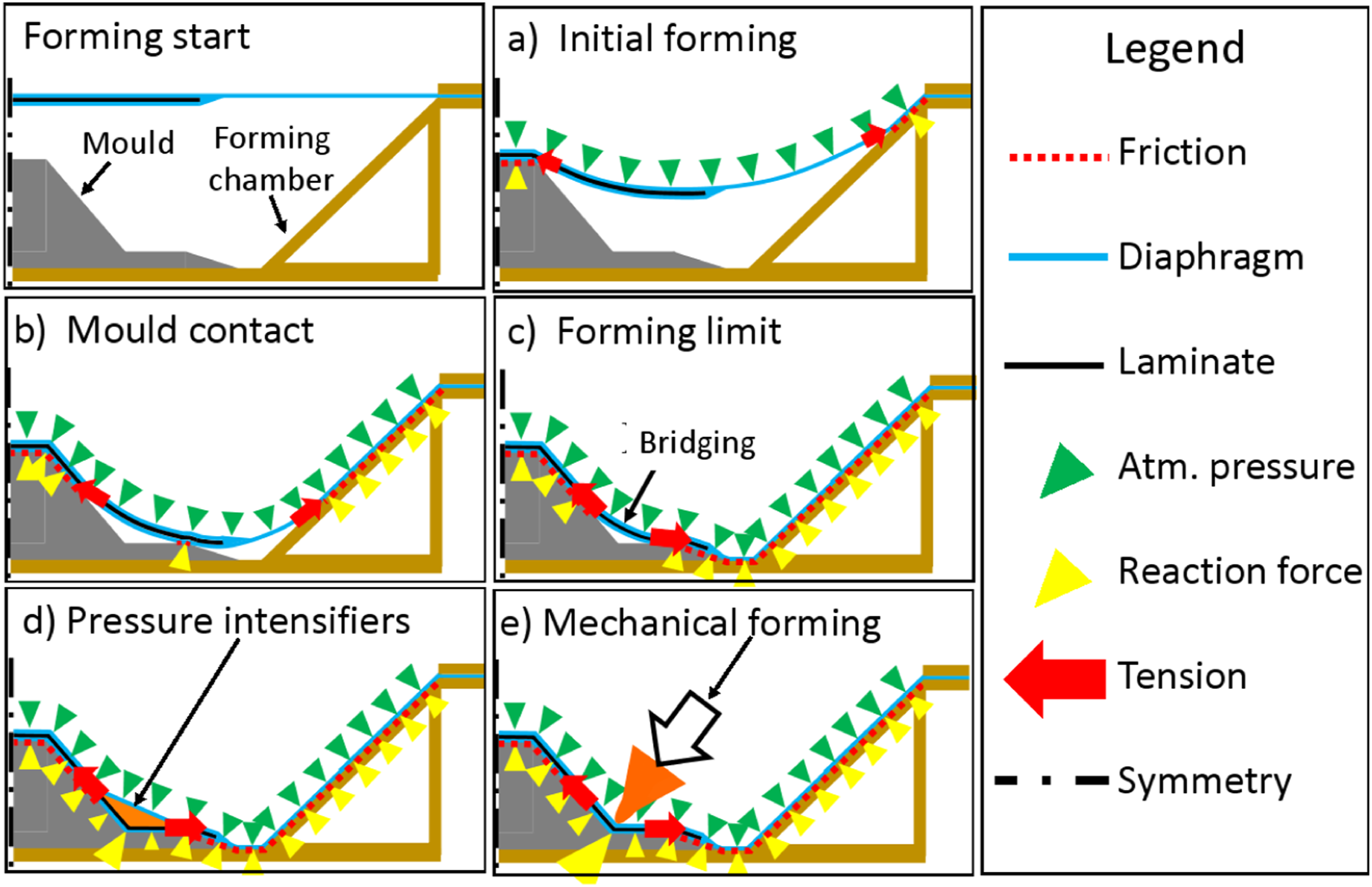
Overcoming ‘bridging’
Bridging during diaphragm forming requires addressing. Where possible, the features of the mould geometry that are susceptible to bridging should be removed or redesigned. Effective techniques to achieve this are to decrease the ratio of ply thickness to mould radius, or to increase the ratio of mould radius to flange length, in this case, the distance to the free edge. 16
Another approach used in diaphragm forming is to operate at an elevated temperature. This has a dramatic effect on the properties of uncured epoxy resin or thermoplastics material, significantly reducing the viscosity. This can reduce the bending stiffness of the laminate 15 and the mould-laminate friction coefficient.15,18 Increasing the temperature also reduces the in-plane properties of the diaphragm material, further assisting the forming. However, the longitudinal stiffness of the fibres will be unaffected by temperature, thus bridging can remain an issue.
Consequently, other forming strategies have been developed to reduce bridging. One approach is to apply additional force on the diaphragm using pressurised gas or fluids. This is used widely to form metals at pressures of up to 1000 MPa (10,000 bar) often referred to as the ‘Hydroforming’ process.19,20 Attempts have been made to apply this concept to composite forming using either compressed air, glycol or water. 20 At such high pressures, the laminate can be prone to damage. To counter this, Yanagimoto and Ikeuchi 21 pioneered protecting the laminate by sandwiching between metal ‘dummy’ sheets during stamp forming, a technique used in other pressure based forming studies.22,23 A drawback of applying forces or pressure across the entire laminate is that the total loading forces can become exceedingly high, requiring large presses or high cost (stiffness) moulds. 20 Additionally, the higher pressure has been shown to cause extra thinning around convex sections and some additional wrinkling. 22
Other designs have replaced the need for a vacuum entirely, including one patent using an airbag to apply a positive pressure to localised areas of the top surface. 24 Rizzolo et al., 25 2019 applied up to 690 kPa of pressure during press forming using a custom designed elastomer-faced tool and a hydraulic press. Another approach was to use magnets to apply compaction forces up to 3 MPa pressure. 26
Pressure intensifiers
An alternative to applying external pressure across the entire laminate is to use Pressure Intensifiers (PI) to locally channel atmospheric pressure into specific areas. In the case of a tight concave radii, the PI is typically a compliant triangular object placed into the corner region between the bag and laminate to increase the pressure in the corner (see Figure 2(d)). 27 However, PIs need to be designed specially to fit the component geometry and precisely locating them in the initial configuration before the vacuum is applied is difficult and prone to human error.
Mechanical forming assistance
While the use of PIs passively focusses the forming pressure into the corner, an option is to use an external device to actively apply a localised force into the corner region, Figure 2(e). A patent by Pham and Harlow, 28 2016, specified a similar hybrid forming process utilising an ‘urging device’ in a variety of configurations to apply a conforming force to the laminate in a concave region. However, no performance results or details of how to apply the ‘urging device’ were given. The design and use of mechanical end effectors to form concave regions is well established both in existing manual29,30 and automated layup processes.31,32
The hybrid vacuum-robotic forming process
Material bridging across concave radii is a common defect in diaphragm or vacuum forming. Methods to overcome bridging include the use of intensifiers and mechanical formers. The latter is best adapted to automation as a compliment the DF process. This work proposes the attachment of the mechanical former (end effector) to a robotic arm to remove the bridging similar to incremental sheet forming (ISF). The hybridised combination of the DF and ISF processes is termed the HyVR (Hybrid Vacuum-Robotic) forming process. The aim of this paper is to define a generalised method by which the DF and ISF processes are sequenced during HyVR. Several mould geometries of increasing complexity will be investigated, and the results will then be used to develop the generalised methodology which will enable users to create appropriate forming strategies for specific mould geometries.
Methodology
The HyVR forming process which combines incremental robotic manipulation and diaphragm forming is presented in this section. Incremental robotic forming was performed using an ABB IRB 6-axis robot, 33 with no additional modifications, as used in previous composite forming studies. 31 An interface fixture was manufactured to permit attachment of various end effector types (tip rounded bar, or ‘point’ and roller) to the robot arm. A force sensor integrated within the end effector would be a logical extension to the current system to permit pressure limited control, however, at forming temperatures, the material is readily pliable and for trial purposes pressure monitoring was not necessary. Furthermore, the end effector was programmed to follow the mould profile less an offset distance representative of the nominal material thickness (2 mm). End effector speed was set empirically so that the point end effector did not drag the laminate across the mould surface. Again, more sophisticated positional and speed control is envisaged for the next generation HyVR system.
The diaphragm forming element was conducted using a custom-built forming chamber (see Figure 3) constructed from 9 mm thick medium density fibreboard (MDF) reinforced with 30 mm x 30 mm cross-sectional struts. Silicone sealant was applied to the MDF to reduce porosity; a loss of vacuum. The laminate (prepreg) was placed by hand on top of the mould in the centre of the chamber. The backing film on the mould facing side of the laminate was first removed. This will have accentuated the friction between the laminate and mould surfaces, but at this feasibility study stage, it is not considered as a major factor. A single diaphragm was sealed around the periphery by clamping a matching frame on the top surface. The diaphragm film used was STRETCHLON HT-350, a typical choice for diaphragm forming. The vacuum was supplied via a Schmalz SBP 15 G02 SDA Ejector system linked to the in-house compressed air supply, producing a stated 85% vacuum. Cross-sectional view of the experimental vacuum forming chamber (Note: not shown to scale).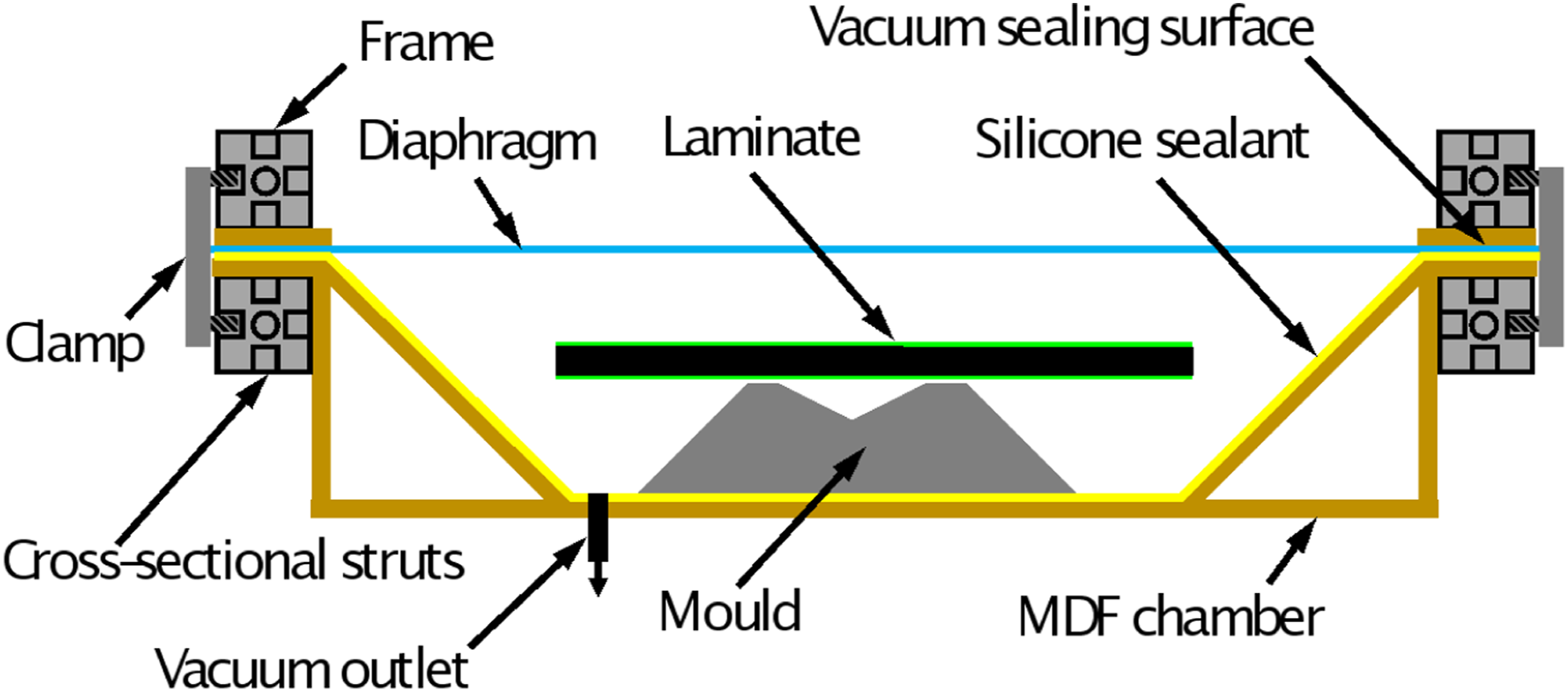
The robot was located adjacent to the vacuum forming chamber such that the end effector could force the laminate onto the mould by pressing through the diaphragm. Importantly, it is the sequencing of the vacuum level and the end effector path that defines the forming strategy for the component. For this reason, a prescribed forming sequence is not defined at this stage.
The laminate material was a 2 × 2 twill woven prepreg carbon (XPREG XC130 450g 12 K).
34
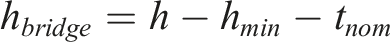
This was used to simulate a fibre reinforced thermoplastic sheet material which would have required an heating system for forming, whereas the XPREG could be formed at room temperature (approximately 23°C). Laminate specimens were prepared comprising four plies (0.45 mm thick per ply) in a 0°/90° configuration, pre-consolidated under vacuum for 10 min prior to the forming. Thus, the standard laminate had a consolidated thickness of 1.8 mm. When the diaphragm thickness is included, the nominal thickness,
Each HyVR forming process undertaken in this study was repeated five times. To quantify the effectiveness of each trial, the conformance of the laminate to the mould in target areas was captured. This was done by measuring the vertical height from the base of the mould to the lowest point of the prepreg upper surface using digital vernier callipers. Referring to Figure 4b, this is the height, h. The distance from the base of the mould to the lowest point of the concave radius is defined as (a) Height, h, of laminate above the mould at the lowest point of the concave radius, h
min
, and the calculated bridging height, h
bridge
, that results, (b) definition of the parameters associated with the bridging height calculation.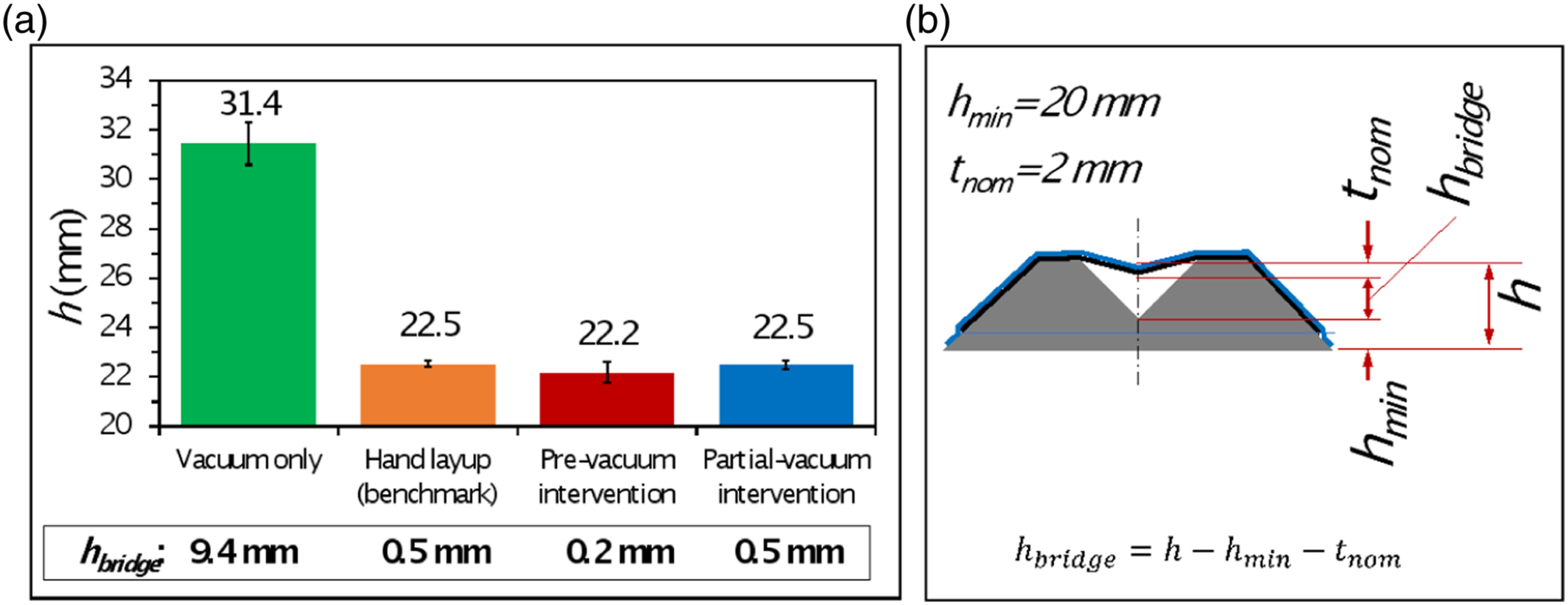
As a comparison, for every mould configuration studied, five benchmark ‘good’ examples were made by an experienced laminator using traditional manual layup techniques. These are referred to as the ‘Hand layup (Benchmark)’ results in the following section.
Results
The HyVR process was developed by investigating its use on three moulds of increasing geometric complexity. In this study, all the are single curvature, which means they do not require any in-plane (intra-ply) shear deformation. Although simplistic, this is representative of many engineering applications such as wing spars and ribs. Common to all three moulds are tight concave radii that are intentionally designed to cause bridging and provide an ideal starting point to develop a fundamental methodology for applying robotic forming. The initial study was carried out on a mould with a single concave feature as shown schematically in Figure 5(a) and discussed in the HyVR-Single feature forming section. Next, a mould with two concave features was used to investigate the complexities of multiple robotic interventions, as discussed in the HyVR-Multi-feature forming section. The final mould, presented in HyVR-A generelised process design methodology section, featured three concave regions of varying radii, requiring the use of multiple end effectors and a more strategic plan of the order in which the features were to be formed. Schematics of the single feature HyVR forming strategies: A. Post-vacuum intervention, B. Pre-vacuum intervention and C Partial-vacuum intervention.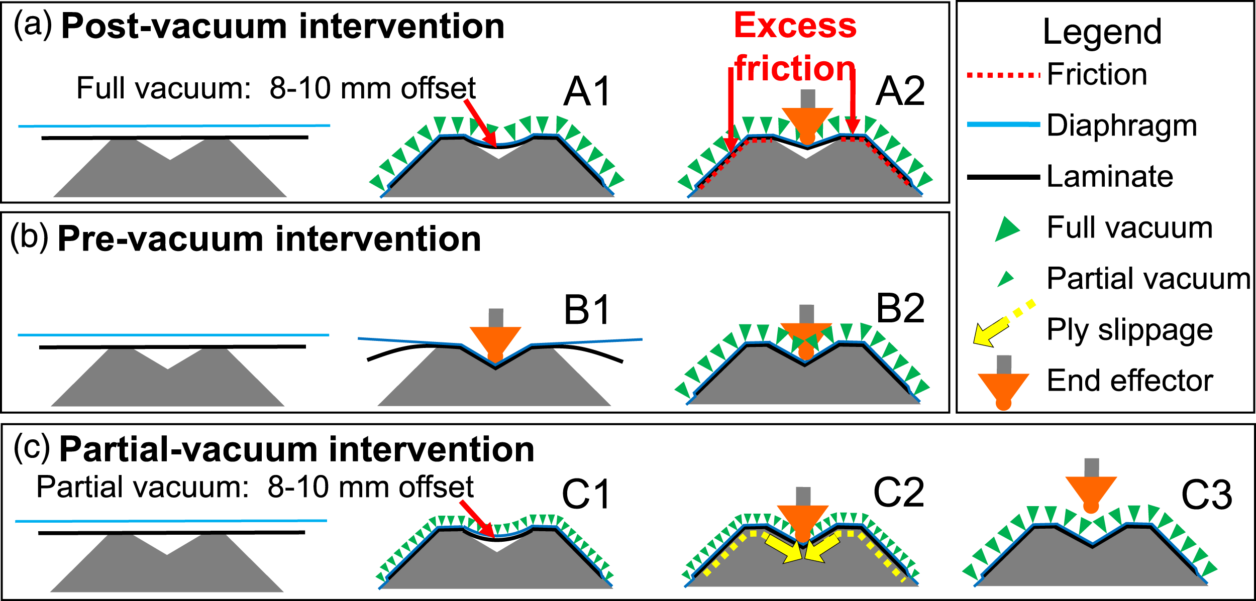
HyVR – Single feature forming
The single feature mould is shown in Figure 5(a) with main dimensions. The end effector chosen for robotic intervention (Figure 5(b)) was a plastic bar having a 2 mm radius tip and a width equal to that of the mould (50 mm), based on a previous tool designed for traditional manual layup. 30
Three different approaches to integrating this end effector architecture into the HyVR process were trialled on this single feature geometry as depicted schematically in Figure 6: A. Post-vacuum intervention, B. Pre-vacuum intervention and C. Partial-vacuum intervention. (a) Schematic of the single feature mould with main dimension, (b) 50 mm wide forming tool with rounded tip.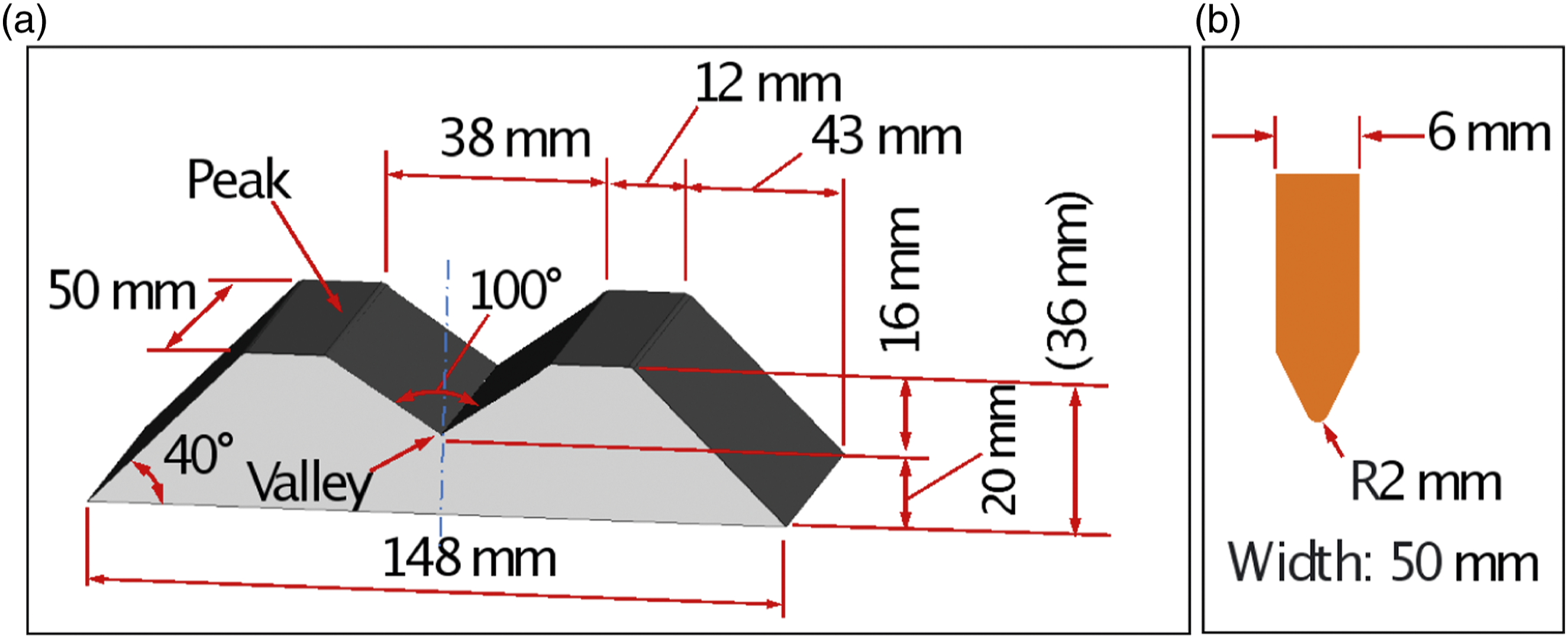
A. Post-vacuum intervention
The first approach is illustrated in Figure 6(a) and consisted of initially applying a full vacuum (A1). This partially formed the laminate into the central valley, or concave corner, of the mould leaving an offset between 8–10 mm. The end effector was then lowered vertically onto the centre of the valley until it contacted the laminate (A2). Due to the significant friction generated between the laminate and mould surface by the vacuum, the force required to push the laminate into the concave corner exceeded the capability of the robot. This limitation could be overcome by using a larger robot or press, but risks damaging the mould or laminate itself.
B. Pre-vacuum intervention
An alternative solution, pre-vacuum intervention (Figure 6(b)), was to contact the end effector ‘before’ vacuum application (B1). This method was highly effective, as the robot easily formed the otherwise unconstrained laminate into the concave corner region (B1). The majority of the forming resistance originates from the out-of-plane bending stiffness of laminate. This is significant but can be overcome easily by the robot. While holding the end effector in position, a vacuum was applied to form the laminate over the mould surface (B2). A shortcoming of this approach is that the end effector must remain in position until the vacuum is applied, limiting the robot to a single forming intervention. If the end effector is removed prior to the vacuum, the out-of-plane bending stiffness of the otherwise unconstrained laminate caused it to elastically ‘spring-back’ and no longer conform to the concave region.
C. Partial-vacuum intervention
The final approach, partial-vacuum intervention, is shown in Figure 6(c). Here, only a partial vacuum is applied initially (C1), achieved by restricting the compressed air supply to the vacuum ejectors. Although not quantitatively measured, the partial vacuum appeared to form the laminate to the same shape achieved by applying the full strength vacuum, leaving an offset of approximately 8–10 mm between the laminate and valley. Next, a vertical intervention is made with the robot (C2). Lastly, after lifting of the end effector, a full vacuum is applied (C3). The partial vacuum reduced the required forming force but was sufficient to prevent unwanted laminate movement during forming after the end effector was removed. All further forming trials will use this partial vacuum approach as a precursor to robotic intervention.
Figure 4a provides a measure of bridging that occurs between the laminate and the valley centre under the different forming approaches. Applying a full vacuum as is the case for simple DF results in an average bridging height of 9.4 mm. A pre-vacuum intervention (B) results in bridging of 0.2 mm versus 0.5 mm for the partial-vacuum approach (C). Both approaches B and C are comparable to the hand layup bridging result of 0.5 mm indicating the effectiveness of the incremental robotic intervention.
HyVR – Multi-feature forming
The initial trials successfully formed a single concave feature using both pre-vacuum and partial-vacuum methods, as shown in Figure 6a and 6b, respectively. To investigate the challenges posed by forming multiple features as likely would be present on a commercial product, a mould was made with two concave regions as shown in Figure 7(a). (a) Schematic of the double concave feature mould showing main dimension, (b) twin-headed end effector and (c) twin-headed end effector equipped with ‘pinning’ pad used in multi-feature forming.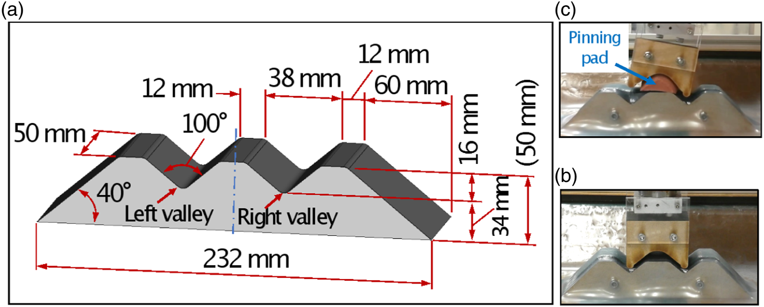
The main concave radius dimensions are the same as for the single feature forming. Three different forming approaches were developed for this mould, as illustrated in Figure 8: A. Simultaneous multi-feature forming, B. Feature-by-feature forming and C. Feature-by-feature ‘pinned’ forming. Schematic of the multi-feature HyVR forming strategies: A. Simultaneous multi-feature forming, B. Feature-by-feature forming and C. Feature-by-feature ‘pinned’ forming.
As found for the single feature forming, applying full vacuum initially caused bridging of approximately 9 mm across each valley. As a result, each of the three approaches were initiated by applying a partial vacuum to the laminate. This held the laminate in position, yet permitted sliding of the laminate across the mould surface.
A. Simultaneous multi-feature forming
The mould has two features with identical geometries, depth and orientation. This enabled the use of a bespoke twin-headed end effector (Figure 7(b)) to form both features simultaneously, as illustrated in Figure 8(a). After applying the partial vacuum to the laminate, the end effector was aligned with the valleys of the mould, then moved vertically downward using the robot (A1). The end effector was removed and a full vacuum drawn for consolidation. This approach proved successful, consistently producing a good mould conformance. Pushing the end effector into the concave corners cause the laminate to slide across the mould, drawing into the left and right valleys (features) in equal amounts from both sides.
B. Feature-by-feature forming
Not all moulds will be suitable for simultaneous multi-feature forming, and the approach requires a bespoke end effector for each new geometry. An alternative approach was to sequentially apply the robot to form each feature in turn as illustrated in Figure 8(b). The first (right) concave region was completed successfully (B1), drawing the laminate inwards from both the left and right of the concave region. However, upon forming the second (left) concave region in step B2, the laminate was again drawn in from both directions. This withdrew material from the initial (right) concave region, undoing the forming achieved in step B1. The end effector was removed and full vacuum was applied. While mould conformity in the left concave region was good, bridging was apparent across the right valley (feature). Furthermore, the level of laminate sliding across the tool was not equal on both sides.
C. Feature-by-feature ‘pinned’ forming
A new approach was developed (Figure 8(c)) to allow sequential feature-by-feature forming while controlling unwanted laminate movement. The twin-headed end effector was supplemented by a silicon pad as seen in Figure 7(c). The purpose of this pad is to ‘pin’ or ‘lock’ the laminate in place (C1) to prevent unwanted movement during forming. This isolates portions of the laminate from the tension generated during forming of concave regions. For example, during step C2, the pinning in the central region means the left-hand side of the laminate is isolated, and material is only drawn in from the right hand side. During forming of the second (left) region in step C3, the pinning force now isolates the right hand side of the laminate, ensuring it is only drawn in from the left, thus preventing the forming completed in the previous step (C2) from being undone. The end effector is then withdrawn and a full vacuum applied for consolidation. The result is good laminate conformity with the mould in both the left and right valleys (features) with equal laminate slippage from both sides.
Figure 9 indicates the level of bridging, h
bridge
, that occurs between the laminate and each of the left and right features (valleys) under the different forming approaches. Relative to the hand layup (benchmark), the three strategies provide excellent conformity with either equal or less bridging. One exception is the right valley (feature) in the feature-by-feature forming strategy. In this case, the bridging is 0.3 mm greater than the benchmark. The variation between the left and right feature for this strategy is 0.5 mm (0.2 vs 0.7, respectively) indicating confirming that forming the left feature after the right feature causes the laminate to withdraw and lift from the mould surface. This fault is rectified by the feature-by-feature pinned strategy as the pinning holds the laminate in the right feature in place while the left is being formed. Measured height, 
Figure 10 illustrates how the laminate slides across the mould during forming. Ideally, the amount of sliding remains equal relative to the left and right hand edges of the mould. This is the case for the hand layup, simultaneous multi-feature (A.) and the feature-by-feature pinned (C.) forming approaches which measure approximately 34 mm from each mould edge. For the feature-by-feature method (B.), there is an undesirable amount of sliding of the laminate across the tool from left to right as a result of the sequential feature forming and indicated by the unequal gap between left and right of 4 mm (36.5 mm and 32.5 mm respectively). (a) Schematic definition of the gap distance between mould and laminate edges and (b) graph of the resulting gaps produced by the forming strategies indicating that Feature-by-feature forming (B.) produces undesirable non-symmetric movement of the laminate across the tool.
HyVR – A generalised process design methodology
The Hyvr-Multi-feature forming section showed that forming multiple features adds an extra level of complexity to the HyVR process. The aim of this work is to define a generalised HyVR process design methodology that is applicable to any mould geometry. This is set out in Figure 11. The following Sections (4.1–4.9) correspond to a specific step in the methodology and the associated decision-making process is presented in the context of a case study. A flow diagram of the generalised HyVR process design methodology.
The case study is based on a mould featuring three distinct concave features of differing geometry as shown in Figure 12(a). The mould featured an open radius concave region in the centre and tight concave regions on either side. (a) Schematic of the ‘triple featured’ mould with main dimensions and (b) selected sequences during the HyVR process forming.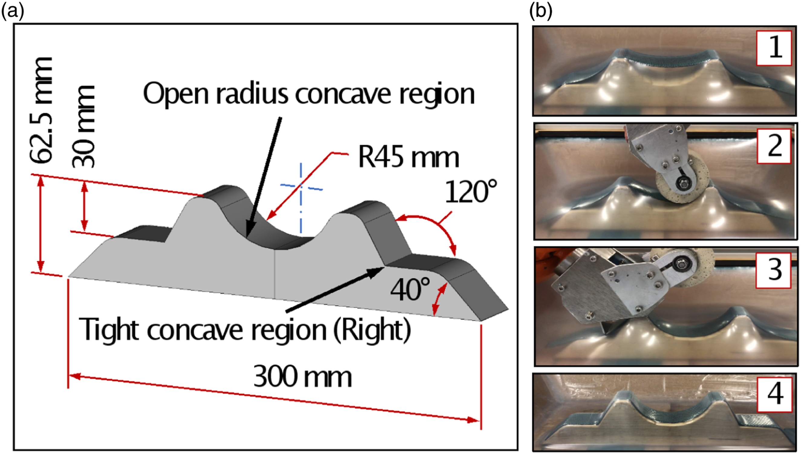
Figure 13 indicates the specific forming methodology for the triple feature mould. Steps A–B are associated with initial positioning of the laminate under partial vacuum. Forming the open radius concave region is described in Steps C–E, the left tight concave region in Steps F–H and the right tight concave region in Steps I–J. Final compaction is shown in Step K. Associated with particular steps are photographs shown in Figure 12(b). Forming sequence developed for the triple feature mould including reference to photographs shown in Figure 12(b).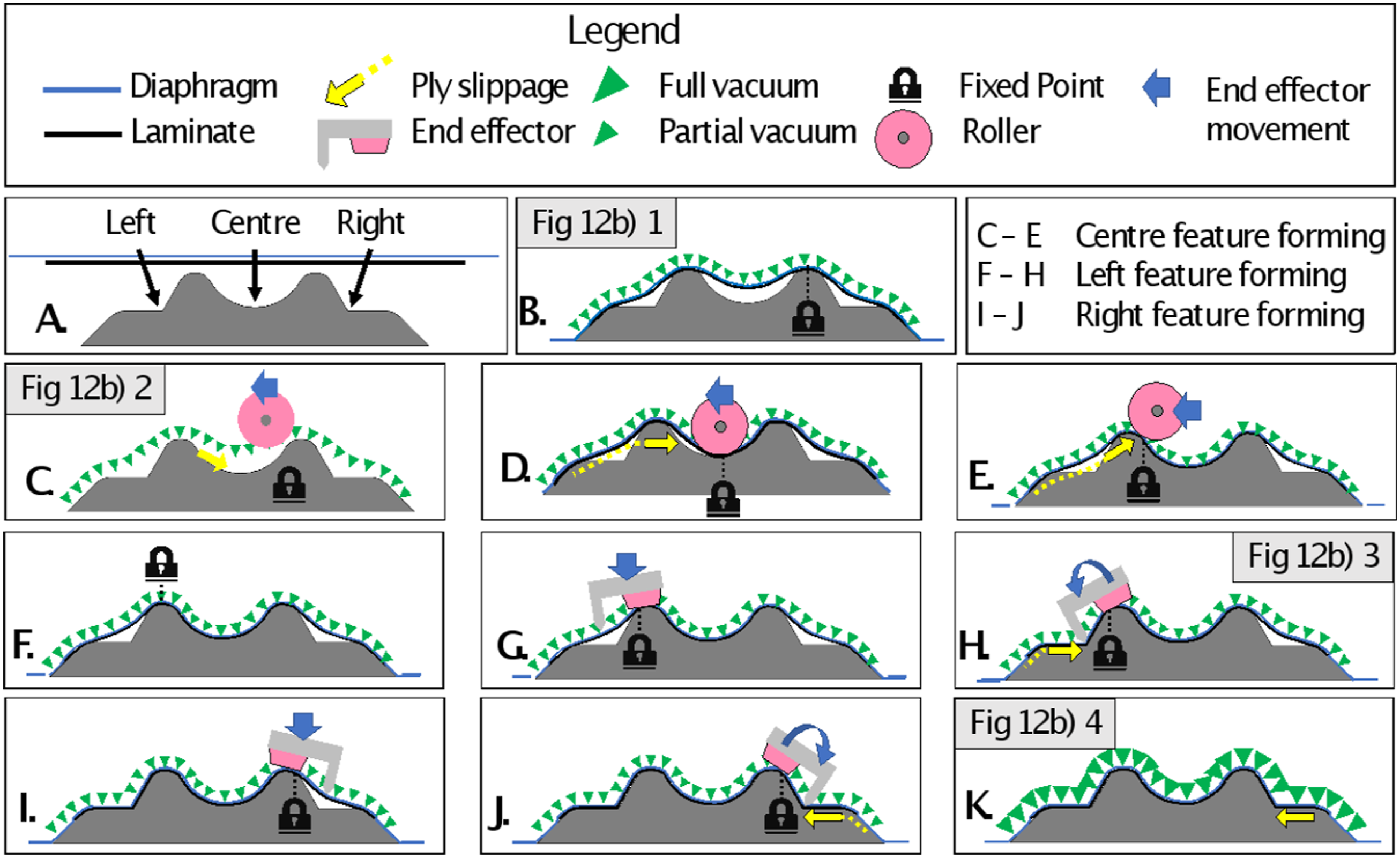
Will standard diaphragm forming result in bridging?
HyVR forming is only required if there are areas on the mould which cannot be formed via vacuum driven diaphragm forming alone. Generally, these are concave recesses as is the case for radii, or negative volumes such as panel rebates to accommodate flush fitting components. For this mould three areas requiring HyVR assistance were identified and are labelled in Figure 13(a) as ‘Centre’, ‘Right’ and ‘Left’. In this study, these regions were identified empirically by forming trials, but they could be detected via simulation. 6
Can all the features be completed in a single action?
For some moulds, the HyVR process can be completed in one action, as was shown on the single feature mould in the HyVR-Single feature forming section. For multi-feature moulds, the features must have similar geometry and size, as was the case for the double feature mould shown in the HyVR-multi feature forming section. This will not always be the case, and some moulds will require separate actions for every feature. There is a wide scope for increasingly complex and specialised end effectors or multiple actuators, such that the limit on what can be done in a single action is not fixed.
Define the first ‘fixed’ point
It was shown that during feature-by-feature forming ‘pinning’ the laminate at a point on the mould surface can prevent unwanted laminate movement and ensure a consistent final laminate position. It is important that the first fixed point is a location where the laminate has contacted the mould during the initial partial vacuum application. This ensures the laminate does not shift as the ‘pinning’ is applied. In this case, the first ‘fixed point’ was placed to the right of the centre region as shown in Figure 13(b).
Define the order the in which the features will be formed
It is important to choose an appropriate order in which to form the features. For example, with three features, there are, by definition, six possible order combinations. The first feature to be formed must be either adjacent to the designated fixed point, or there must not be a concave feature between it and the fixed point. In this case, with the fixed point located between the Right and Centre regions, either one could be the first to be formed. The Left region could not be selected as the starting point because there is a concave feature, the Centre region, between it and the fixed point. Another consideration when defining the order is a region must never be ‘trapped’ by having regions in both directions being formed before itself. For example, if the Left and Right regions are formed first, the central region would be ‘trapped’ between them. When it is subsequently formed, the generated in-plane tension would ‘un-form’ one or both of the other regions. Therefore, the Centre region must be formed either first or second, with one of the Left or Right regions formed last. In this version, the order will be Centre, Left, then Right.
Select the next feature to be formed
Once an order has been established the features must then be assessed individually to determine the best approach for each. Below are descriptions of the design process for each of the three features in turn.
Centre feature: (Figure 13(c)–(e))
Centre feature: Define local ‘fixed point’
The fixed point for the first feature is already defined as shown in Figure 13(b), but for each subsequent step, a new fixed point may be required.
Centre feature: Which end effector(s) is required?
It is crucial to match mould geometry to the correct type of end effector. 3 The centre region has a much larger radius than the concave features (valleys) encountered previously, thus requiring a different approach. A large end effector with a matched curvature is one option, but a more adaptable approach is to use a deformable roller. This is a common end effector for composite forming, being almost ubiquitous across AFP and ATL machines 1 as well as being used in prototype manufacturing processes.31,32 The roller allows the consolidation of a larger, more varied area than a pointed end effector, and can move across the surface, friction free, without breaking contact.
Centre feature: Specify roller path
Once the end effector has been selected, its movements during forming needs to be specified. The centre region will be completed by a roller which, in addition to forming, can also pin the laminate onto the mould. As the roller moves across the mould, the front portion (left as pictured) of the roller carries out forming, while the rest of the contact area does the pinning, preventing any slip of the laminate across the mould surface. To make full use of this pinning, the first contact of the roller, as depicted in Figure 13(c) occurred at the ‘fixed point’, which had already been fully formed by the partial vacuum. This secured the laminate and then the roller was moved from right to left through the concave region. This approach proved successful, with only material from in front of the roller (left as pictured in Figure 13(d)) moving across the tool to allow forming.
Left feature: (Figure 13(f)–(h))
Left feature: Define local ‘fixed point’
Due to the close proximity of the Left region to the concave curvature of the Centre region, it was deemed necessary to create a second fixed point. This may not be required if there is a considerable distance between the two features as the laminate to mould friction would be enough to prevent any movement. The new fixed point is located on the left of the two high points, as seen in Figure 13(f).
Left feature: Which end effector(s) are required?
The left feature has a tight radius and is best formed by a ‘point’ style end effector rather than a roller. In this example, the ‘point’ end effector was integrated into the same robot attachment as the roller to avoid the need for time consuming and complex tool changes. The pinning was achieved with a silicone pad located near the point end effector as shown schematically in Figure 13(h). Note that in Figure 12(b), the silicone pad is obscured from view by the structure of the robot attachment.
Left feature: Specify end effector movements
Using the same technique as was shown in feature-by-feature forming, the silicone pad is lowered onto the laminate and ‘pins’ it in position on the mould. The whole robot attachment then rotates to move the point end effector into the corner region (see Figure 13(h)).
Right feature: (Figures 13(i) and (j))
Right feature: Define local ‘fixed point’
To protect the centre region from re-bridging due to in-plane tension generated during forming, a fixed point was required while forming the right region. In this case, the original fixed point (Figure 13(b)) was reused. The rest of the forming process is a mirror image of the left feature so will be omitted from this description.
Final consolidation: (Figure 13(k))
Once all three features had been formed, a full vacuum was applied to draw the laminate firmly onto the mould surface (see Figure 13(k)).
Summary
This study has shown that robotic end effectors can successfully assist in the forming of concave features otherwise impossible with standard diaphragm forming. The process is rapid with the robotic intervention for the triple feature mould adding only 20 s to the standard diaphragm forming process. Furthermore, the process was not optimised for speed and considering industrial robots can move in excess of 2000 mm/s the actual incremental robotic intervention could be very short. While a robot was used in this application to control the end effector, a simple gantry-based system may be a more economical alternative.
Conclusions
This work presents examples of traditional diaphragm forming of composites with the novel integration of robotic incremental (sheet) forming creating a new technology called the HyVR process. The aim to define a generalised HyVR process design methodology that is applicable to any mould geometry has been met with context provided as a case study. It has been demonstrated that HyVR can overcome long standing ‘bridging’ issues in diaphragm forming by applying additional forces in the concave regions at specific moments in the diaphragm forming process. This opens the diaphragm forming technique up to a wider range of mould geometries featuring multiple concave regions and negative volumes. It could be used for manufacturing prototype components or equally, supporting medium volume production runs up to 30,000 parts per annum.
The variety of approaches trialled in this study have shown that applying a force via the end effector to a laminate under full vacuum can require prohibitively high forming forces making it unviable for low cost composite manufacture. Instead, applying only a partial vacuum provided a balance of preventing unwanted movement of the laminate while minimising the friction to enable the robotic interventions. It was also found that for a mould with two or more features, a pre-planned forming strategy was required to ensure the finished laminate correctly conformed to the mould. An incorrectly planned process was shown to cause previously formed features to re-bridge during subsequent operations. In addition, undesirable movement of the laminate across the mould could result. A generalised methodology for creating a forming strategy was developed and is explained in context of forming a mould with three concave features of varying geometry. A fundamental aspect is the use of ‘pinning’ to secure the laminate in specific locations. This is used to dictate movement of the laminate during forming and ensure consistent locating of it in the finished component.
Demonstration of the HyVR process within this work was performed using prepreg which has the benefit of being formable at room temperatures. Preliminary findings suggest that the HyVR process is effective in forming double curvature features in addition to the single curvature geometry demonstrated in this work. The further intention is to extend the HyVR process for use with fibre reinforced thermoplastic matrix composites, particularly those in pre-consolidated sheet form. This will add the complexity of temperature dependence to forming and require consideration of in-situ heating.
Supplemental Material
Footnotes
Correction (October 2022):
Article updated to correct figure 6 in the paper.
Declaration of conflicting interests
The author(s) declared no potential conflicts of interest with respect to the research, authorship, and/or publication of this article.
Funding
The author(s) disclosed receipt of the following financial support for the research, authorship, and/or publication of this article: This work conducted as part of a feasibility study funded by the Engineering and Physical Sciences Research Council through the EPSRC Future Composites Manufacturing Research Hub [Grant number: EP/P006701/1]. The second author would also like to acknowledge the funding support of the EPSRC Industrial Doctorate Centre in Composites Manufacture [Grant number: EP/L015102/1].
Supplemental Material
Supplemental material for this article is available online.
References
Supplementary Material
Please find the following supplemental material available below.
For Open Access articles published under a Creative Commons License, all supplemental material carries the same license as the article it is associated with.
For non-Open Access articles published, all supplemental material carries a non-exclusive license, and permission requests for re-use of supplemental material or any part of supplemental material shall be sent directly to the copyright owner as specified in the copyright notice associated with the article.