
Abstract
The present study concentrates on a series of experiments and numerical analyses for understanding the effects of fiber volume fraction (VF) and draw ratio (DR) on the effective elastic properties of unidirectional composites made from an epoxy resin matrix with a continuous fiber reinforcement. Lyocell-type regenerated cellulose filaments (Ioncell) spun with DRs of 3, 6, and 9 were used. In accordance with the specimens in situ, the fibers were modeled as slender solid elements, for which the ratio between the diameter and length was taken to be much less than unity and deposited inside the matrix with the random sequential adsorption algorithm. The embedded element method was thereafter used in the numerical framework due to its computational advantages and reasonable predictions for continuous fiber reinforced composites. Experiments and numerical investigations were carried out, the results of which were compared, and positive trends for both fiber VFs and DRs on the effective properties were observed. The presented experimental and numerical results and models herein are believed to advance the state of the art in the mechanical characterization of composites with continuous fiber reinforcement.
Keywords
Introduction
The successful transition to a bio-based economy requires performance materials made from renewables.1–4 As illustrated in Figure 1, the end products of interest have thus far been garments, consumer goods, packaging products, and structural components, just to name a few. It is known that the incorporation of renewable materials into various matrices can provide not only bespoke performance but also increased sustainability.5–7 For instance, continuous fiber reinforced polymer composites are well-known and widely used examples that are light and strong and have versatility in a broad range of engineering and consumer product applications. For these types of composites, regenerated cellulose fibers, which have been demonstrated to have favorable properties compared to their natural counterparts, can replace synthetic reinforcements.8–10 Furthermore, the fiber spinning process, as part of the regenerated fiber process path, allows the production of tailor-made fibers which is of advantageous in terms of design and manufacturing constraints.11–14 Although composites from regenerated cellulose fibers have been attracting a lot of attention to date, the numerical analysis of these types of composites has been lagging behind due to the computational costs and unknown material characteristics in continuous fiber modeling, for example, single-fiber characteristics and interactions between fibers and the matrix.15,16 Therefore, in order to contribute to the current state of the art from this perspective, a series of experiments at the single fiber (constituent) and composite (material) level integrated with the numerical analyses were carried out. Process path for regenerated fibers and their end products.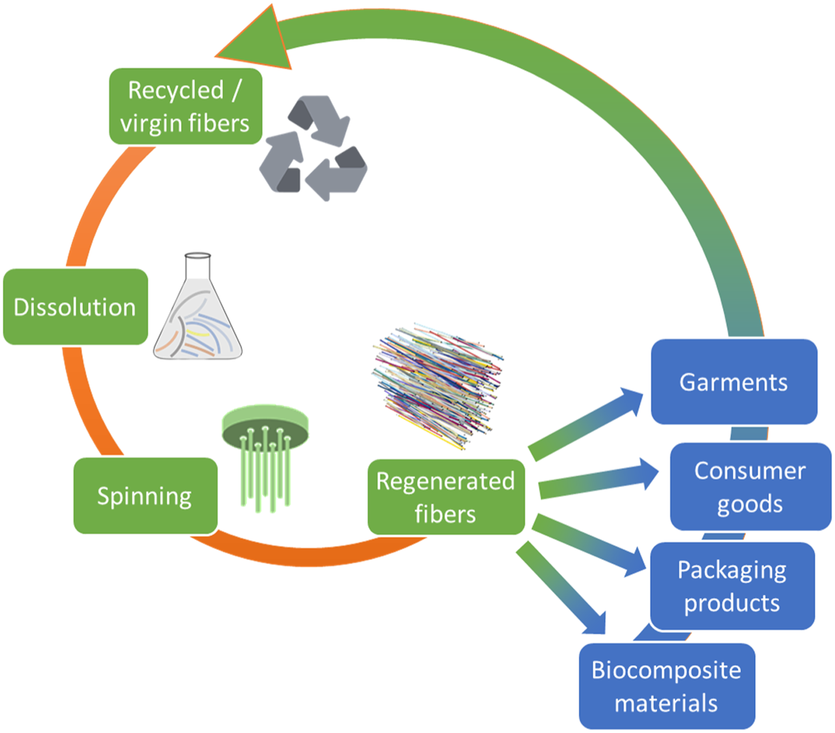
Herein, a novel method to produce regenerated cellulose fibers was implemented, through which the ionic liquid (IL) 1,5-diazabicyclo[4.3.0]non-5-ene-1-ium acetate ([DBNH][OAc]) acted as a solvent in the production of the fibers referred to as Ioncell.17,18 Ioncell fibers belong to the class of lyocell fibers: Cellulose is dissolved directly without prior derivatization and spun via an air gap into an aqueous coagulation bath. Through adjusting the take-up speed of the solidified fibers to a multiple of the extrusion velocity, the liquid filaments are stretched in the air gap. This so-called draw exerts uniaxial stress on the cellulose polymers in solutions and promotes their orientation along the fiber axis. The anisotropic structure is transferred to the final solid fiber through rapid solvent exchange and coagulation in the water bath. With increasing draw ratio (DR), the total and amorphous orientation of the cellulose polymers rises. 10 This leads to an increase in both tensile strength and modulus. 19 This type of fiber is reproducible with a highly consistent mechanical performance and is thus suitable for composite preparation as well as being favorable for mathematical modeling. The effects of volume fraction (VF) and the DR of these fibers on the elastic properties of their unidirectional composites were investigated in detail through experiments, modeling, and analysis using numerical methods. Within this scope, single-fiber mechanical characteristics were, initially, measured in a series of tensile tests demonstrating the positive effects of DRs on the fiber stiffness and tensile strength characteristics. The fiber properties were then integrated into the three-dimensional numerical model for the predictive characterization of the unidirectional composites made from an epoxy resin matrix and continuous fiber reinforcement. In order to be consistent with the spatial and geometrical features of the fibers in the tested specimens, the random sequential adsorption algorithm for fiber deposition was implemented in the numerical analyses, which was previously elaborated by the authors.20,21 The deposited fibers were then constrained within the matrix through a low-cost mesh superposition technique, the so-called embedded element method. In this method, fibers are taken to be an additional axial component embedded in the matrix with consistent nodal displacements instead of the separately modeled matrix and fiber interactions. 22 The method was developed to investigate localized deformation and damage.23,24 It was first applied to investigate the nonlinear material behavior of reinforced concrete because of its applicability for large solution domains with low computational costs.25,26 Thereafter, it was extended to investigate the effective elastic properties of fiber reinforced polymer composites, especially for the ones reinforced with continuous or woven fibers. 27 In recent years, it has been also implemented in the fields of biomaterials and biomechanics, to name but a few, for the characterization of 3-D collagen scaffolds 28 and investigating traumatic brain injuries to the human head with embedded axonal fiber tracts under impact loading scenarios.29,30 In consideration of its versatility and computational efficiency, as deduced from the literature, the embedded element method was implemented in the present investigations so as to understand the mechanical characteristics of composites that are nowadays in the process of replacing plastics and other nonrenewable materials.
The results obtained from the present numerical framework were finally compared with the tensile test results of the unidirectional composites. Both numerical and experimental investigations demonstrated the positive influences of the fiber VFs on the uniaxial stiffness properties of the regenerated cellulose reinforced composites as well as the examined DRs. As a result, it was deduced that the framework based on the embedded element method can provide computationally feasible solutions, especially for understanding the effects of constituent parameters on the effective elastic properties of continuous fiber reinforced (bio)composites.
Materials and methods
Regenerated cellulose fiber manufacturing
[DBNH][OAc] was prepared by adding an equimolar amount of acetic acid (glacial, 100%, Merck, Germany) to 1,5-diazabicyclo[4.3.0]non-5-ene, DBN (99%, Fluorochem, UK). Birch (Betula pendula Roth) prehydrolysis kraft pulp ([η] = 476 mL/g, DP = 1133, Mn = 65.9 kDa, Mw = 269.3 kDa, polydispersity index 4.1, Enocell Speciality Cellulose, Finland) was dissolved in pre-molten [DBNH][OAc] using a vertical kneader system as described previously. 31 Air-dried pulps were mixed with [DBNH][OAc] and kneaded for 1.5 hours at 80°C and 10 r/min under reduced pressure (50–200 mbar). The solutions were thereafter filtered by means of a hydraulic press filtration system using woven metal filters with 5 μm absolute fineness (Gebr. Kufferath AG, Germany) at 80°C to remove undissolved substrate impurities. Filaments were spun on a customized laboratory piston spinning system (Fourné Polymertechnik, Germany) following the previous investigations of the authors available in the literature.32,33 The spin solution was then extruded through a 36-hole spinneret with a capillary diameter of 100 μm and a length-to-diameter ratio (l/d) of 0.2. After passing through a 1 cm air gap, the filaments were coagulated in a water bath (15°C) in which the filaments were guided by Teflon rollers to the godet couple. The extrusion velocity (ve) was varied with respect to take-up velocity (vtu) in order to achieve DRs of 3, 6, and 9. The DR is defined as DR = vtu/ve. The fibers were washed in hot water (60°C) and dried in air. The mechanical properties of the fibers were determined as described in Section 2.3.
Unidirectional composite manufacturing
A bespoke glass mold was built in order to prepare composite samples. The dimensions of the samples were 5 mm in width and 75 mm in length. Ioncell-F fibers were manually laid on the surface and gently fixed with a scotch tape to prevent misalignment during the application of liquid resin. The mold was pretreated with a release agent (Chemlease 75, ChemTrend, USA) to ease the removal of samples. Epoxy resin (Araldite LY5052; Huntsman, US) was mixed with the hardener (Aradur 5052) in the ratio 100:38 by weight according to instruction of the manufacturer. The mixture was stirred for around 30 min under vacuum to remove entrapped air. The degassed resin was poured onto the fibers in the glass mold, and another glass plate was placed on top in order to spread the resin evenly and achieve a constant specimen thickness of around 30 μm. After 24 h of curing at ambient room conditions, the composites were placed in a conventional oven for 4 h at a temperature of 120°C to post cure them. Finally, the composites were removed from the molds and laser cut into a dumbbell shape samples type 1BB according to ISO 527-2 (length 30 mm; narrow portion of the sample 2 mm). Composites with the fiber weight fractions of 20%, 30%, 40%, 50%, and 60% were prepared. Their corresponding fiber VFs were computed through
Tensile testing of single fibers and unidirectional composites
Single-fiber diameter (μm) as well as tensile modulus (GPa), tensile strength (MPa), and elongation (strain at break %) were measured using a Vibroskop-Vibrodyn 400 system (Lenzing Instruments GmbH & Co. KG, Austria). At least 10 single fibers of each type were tested. Prior to and during the tests, all fibers were kept in a controlled environment of 23°C and 50% RH. The tensile testing of composites was carried out using a Tinius Olsen H10KT (Tinius Olsen TMC, USA) universal test machine at a speed of 15 mm/min. The machine was equipped with hardware and software required for data capture and parameter control. The test samples were prepared following standard ISO 527-1:2012 for plastics. During testing, the gauge length of each specimen was set to be 35 mm. Displacements and strains were measured from the cross-head transducers, while the thickness and width of the samples were measured by using a micrometer in three locations and then arithmetic average was used for the calculations. A minimum of five samples were tested in each group.
Three-dimensional geometric formation of fibers and unidirectional composites
In order to generate continuous fiber reinforced composites and study the effects of VF and DR on the mechanical characteristics, a statistical geometrical model was implemented by using the random sequential adsorption algorithm.20,21 The model consists of a geometrical description of fibers, planar projection, deposition, and fiber trimming operations, which was elaborated in the previous work of the authors. 35
As seen in Figure 2, each fiber was described in terms of its spatial properties, that is, centroid C (X
i
. Y
i
. Z
i
) and Fiber profile and distribution: (a) fiber spatial properties in the global XYZ-Cartesian coordinate system and geometrical properties in the local xyz-Cartesian coordinate system and (b) specimen in the global XYZ-Cartesian coordinate system.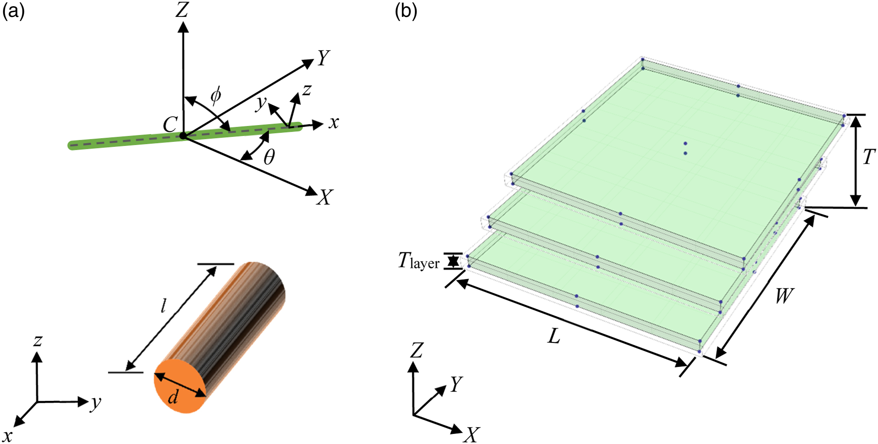
In order to define the spatial distribution of the fibers, fiber centroids C (X
i
. Y
i
. Z
i
) were first generated with a uniform probability distribution on layers represented with the predefined length L and width W in the XYZ-Cartesian coordinate system. Here, the Z coordinates of centroids were set based on the layer height. As seen in Figure 3, Monte Carlo simulations were then used for random selection and picking of each C (X
i
. Y
i
. Z
i
) in an iterative manner. By this way, selection of same fiber centroids was avoided. Schematic representation of Monte Carlo simulations for random centroid selection.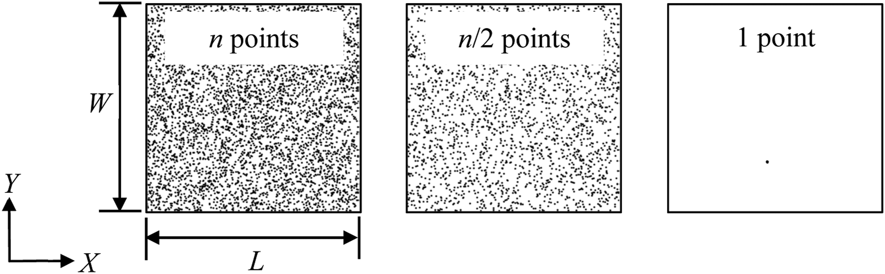
Fibers were then generated and deposited into the predefined specimen domain as illustrated in Figure 2b one after another by picking the distributed fiber centroids illustrated in Figure 3. Throughout the fiber deposition process, VF was used as the controlling parameter, and fiber overlapping was monitored in an iterative manner—that is, if there is no overlapping with the adjacent fibers, the deposited ones remained fixed throughout the process. As seen in Figure 4, fiber reinforcements were generated and embedded into the matrix material. Both fiber and matrix material were discretized by using eight noded linear hexahedral elements C3D8 provided by the ABAQUS finite element solver.
36
Continuous fiber reinforced composite specimen generated with the present model and an embedded fiber discretized with eight noded hexahedral C3D8 elements.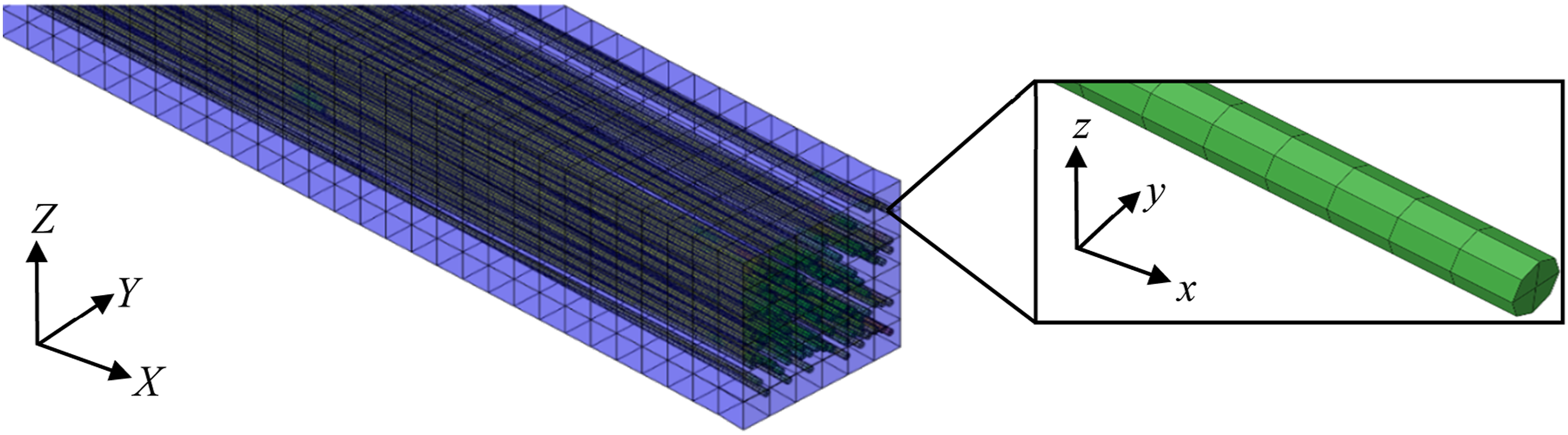
Embedded element method
In the present study, the embedded element method, a mesh superposition technique, provided in the ABAQUS finite element software was used to determine the effective elastic properties of the continuous fiber reinforced composites.
36
The method aims at overcoming the mesh generation and convergence problems for the fiber–matrix interface.
37
It is a useful modeling approach for the numerical analyses under the assumption of no slip between the fiber and matrix.
38
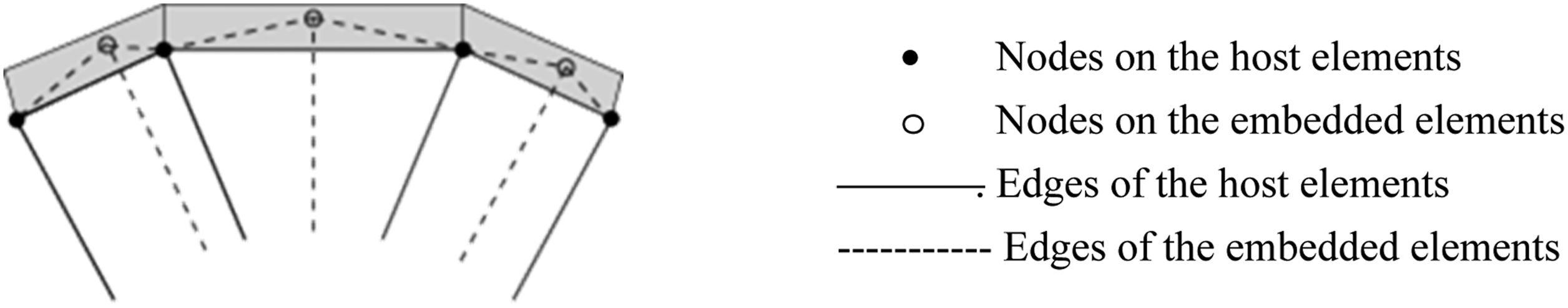
In this method, the fibers (embedded elements) are embedded inside the matrix (host elements), which are schematically represented in Figure 5. The translational degrees of freedom (DOFs) of the embedded element nodes are constrained to the interpolated DOFs of the neighboring host element nodes N. However, rotational DOFs are not constrained.
39
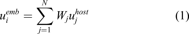
The relationship for the translational DOFs between the embedded and host element nodes was previously formulated as
40
Schematic representation of the embedded elements inside the host elements.
36
Results and discussions
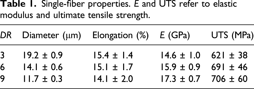
Single-fiber properties. E and UTS refer to elastic modulus and ultimate tensile strength.
In consideration of the fiber geometry, orientation, and VFs mimicking the manufacturing process, the abovementioned random fiber deposition technique was implemented where the untrimmed fiber has a length, l, of 10 mm, average diameter of 14 μm, in-plane orientation θ of 0°, and polar orientation ϕ of 0°, and the matrix has the dimensions of L = 10 mm, W = 0.3 mm, and T = 0.3 mm. The fibers exceeding the matrix boundaries were trimmed, and fiber length distribution after trimming operations was provided for the specimens with Fiber length distribution for the generated specimens with (a) VF of 16.7%; (b) VF of 25.5%; (c) VF of 35%; and (d) VF of 55%.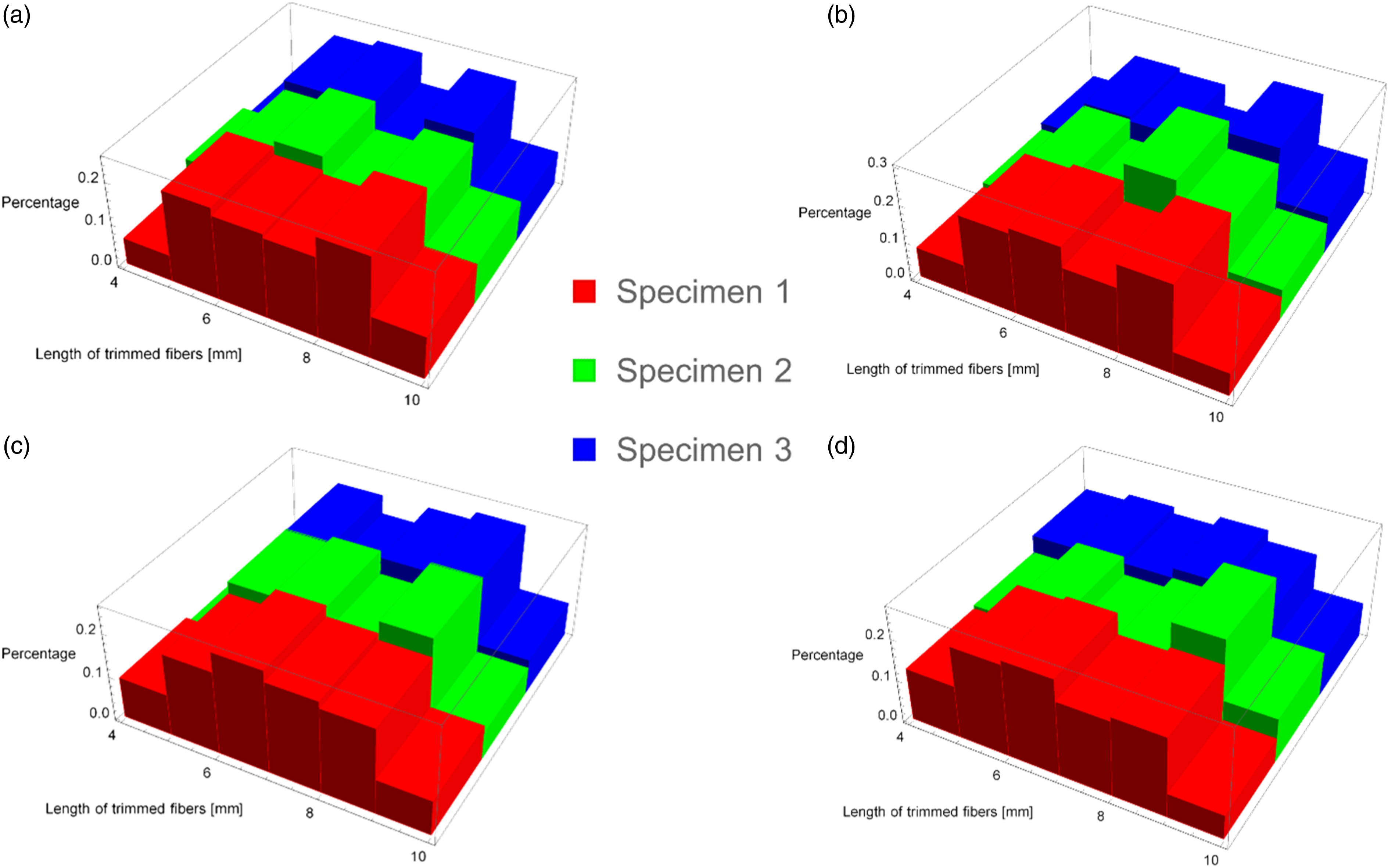
The specimen geometries generated were discretized to establish the solution domain for the finite element analysis. The embedded element method was implemented to kinematically constrain the fiber (embedded element) nodes and matrix (host) nodes. The material properties were then assigned to the fiber and matrix regions in the domain. The single-fiber properties listed in Table 1 and the elastic modulus (E = 2.2 GPa) and Poisson’s ratio (v = 0.3) for the matrix (Araldite LY5052) previously measured by the authors were applied.
41
Thereafter, Dirichlet boundary conditions were used at both ends of the specimens mimicking the uniaxial testing cases: one end was fixed and the other end had a displacement of u
X
= 0.05 mm along the specimen length. Finally, the numerical analyses were conducted by using the general static analysis in order to obtain the linear elastic response of the specimens. The reaction forces at the end nodes Fi were collected and summed up to find the total force Ftotal. The nominal stress and strain were computed through Scanning electron microscopy micrograph of composite with fiber draw ratio (DR) of three and volume fraction (VF) of 55% and its numerical counterpart showing the uniaxially aligned fibers and matrix.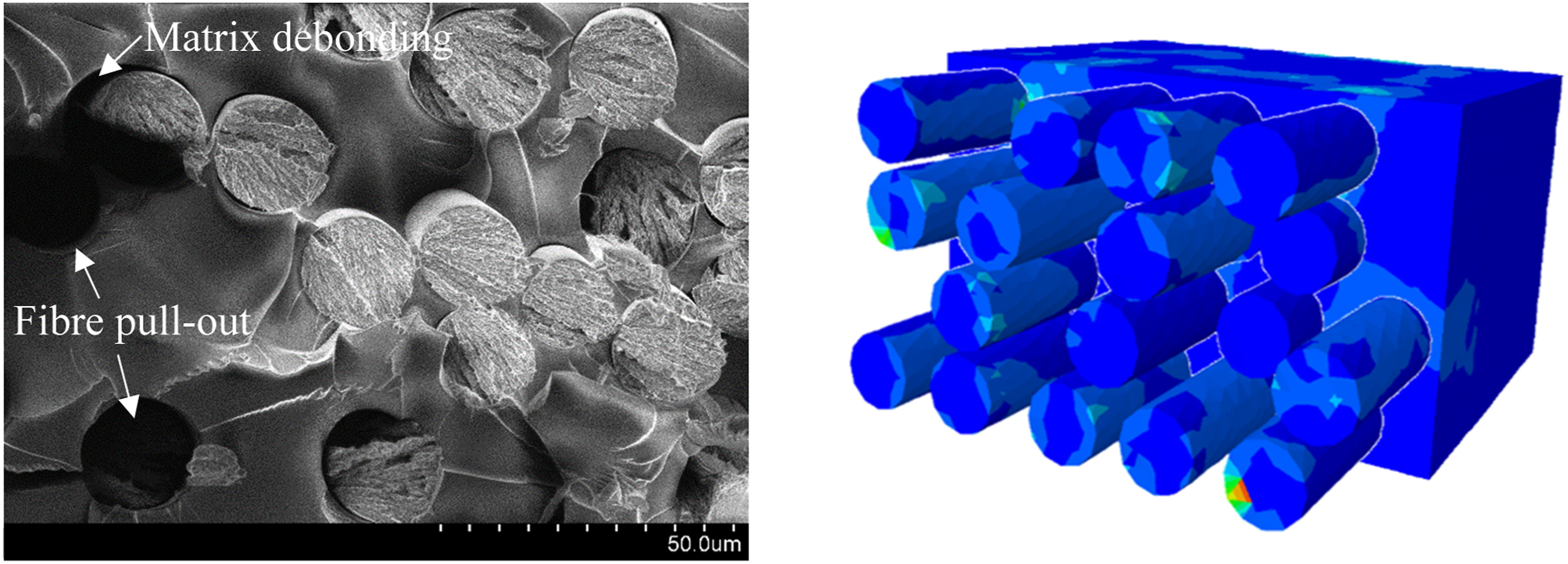
Based on the plots in Figure 8, the positive effect of VF is clearly observed; however, there exists a slight decrease in the experimental elastic modulus at the loading of 25.5 vol% for the fibers with DR = 3. This could be attributed to the uneven distribution of fibers due to their larger diameters. On the other hand, although the stiffness of the Ioncell fibers with DR = 9 is nearly 20% higher than that of DR = 3, this is not evident in the performance of their composites. Therefore, there is no statistically significant difference of elastic moduli with respect to the DRs. Experimental and numerical elastic moduli based on the present uniaxial tension tests: (a) fiber draw ratio of 3, (b) fiber draw ratio of 6, and (c) fiber draw ratio of 9.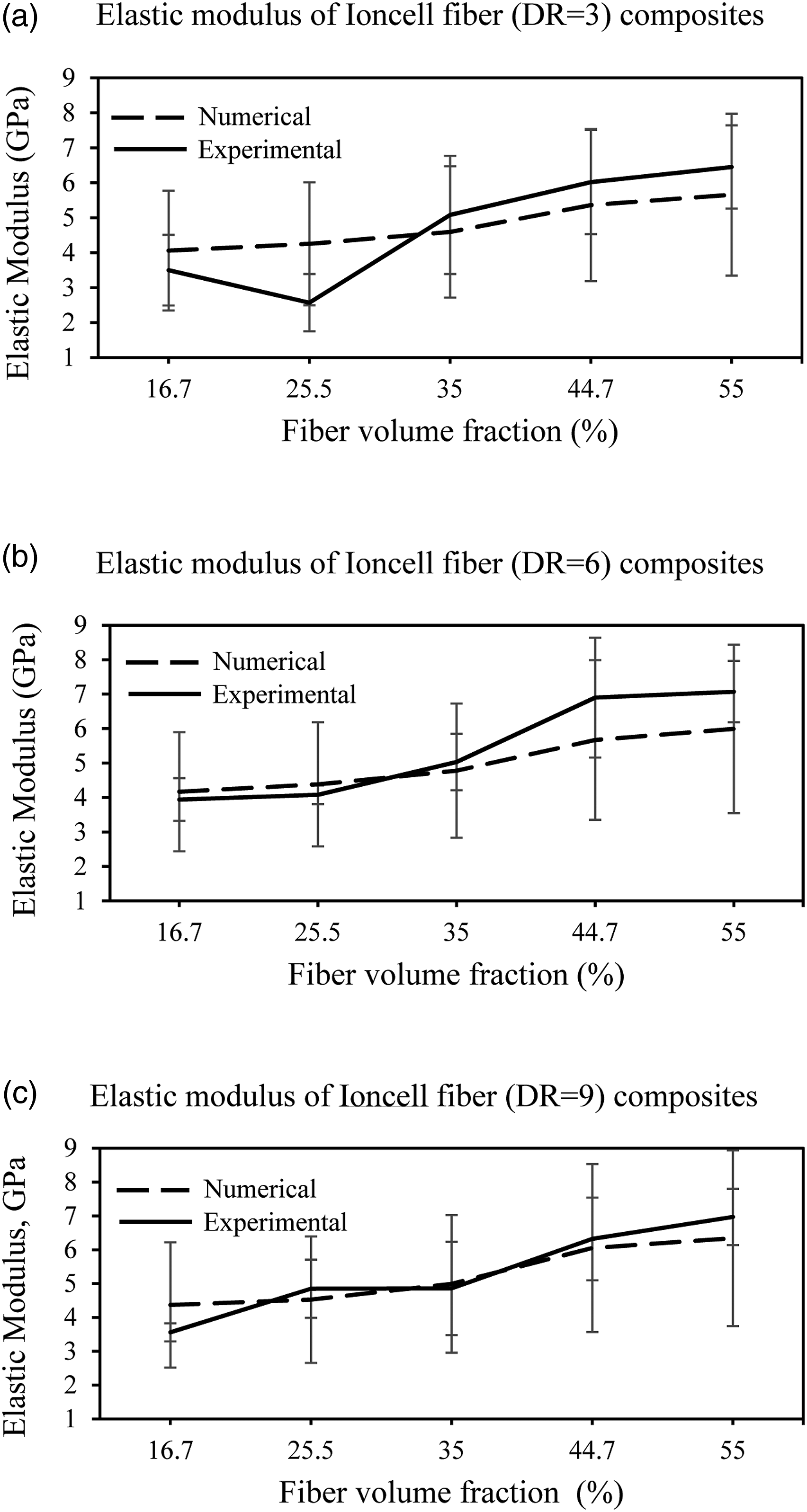
Conclusions
The present study provided a systematic approach to characterize the Ioncell regenerated cellulose fiber reinforced composites and to understand how fiber VF and the properties of the reinforcing fibers affect their elastic moduli. For this purpose, single fibers and their unidirectional composites were tested, and the measured properties were used in the numerical analysis to provide a predictive characterization workflow. In the numerical framework, the random sequential adsorption algorithm for the fiber deposition and embedded element method for the kinematic constraints between the fibers and matrix were used, which aimed at generating a computationally efficient yet reliable analysis tool for large and complex solution domains.
Based on the comparative investigations on the elastic modulus of the Ioncell regenerated fiber reinforced composites, the relative error was obtained to be within a range of ∼4.6%–∼17.9%. In addition to this, the fiber VF was observed to have a positive influence on the elastic modulus, while the DR was deduced to have no significant effect. As a result of this study, Ioncell fibers and similar lyocell-type fibers and their composites were demonstrated to have favorable mechanical characteristics compared to their natural counterparts. It is believed that these regenerated fibers and the composites can replace the synthetic ones, which can contribute to the circular economy and reduce the carbon footprints drastically.
Footnotes
Acknowledgement
The authors wish to acknowledge the CSC – IT Center for Science, Finland, for computational resources.
Declaration of conflicting interests
The author(s) declared no potential conflicts of interest with respect to the research, authorship, and/or publication of this article.
Funding
The author(s) disclosed receipt of the following financial support for the research, authorship, and/or publication of this article: AK would like to acknowledge the funding through the postdoctoral researcher position at Aalto University Department of Bioproducts and Biosystems, the research fellowship at the School of Electrical Engineering, and funding from the Academy of Finland BESIMAL project (decision number 334197). MB and SS are grateful for the financial support to the Research Council of Lithuania under the grant number S‐MIP‐19‐390.