
Abstract
This study presents four different impeller designs to compare hydrodynamic forces. Numerical simulation studies are performed via computational fluid dynamics to specify and investigate the hydraulic forces impacting the impeller of the mixed-flow blood pump with a volute. The design point of this pump is that the flow rate is 5 L/min, the rotational speed is 8000 rpm, and the manometric head is 100 mmHg. The designed impellers are placed in the same volute and simulation studies are performed with the same mesh size (17.3 million cells) of the pumps. The simulation studies have been conducted in setting 1050 kg/m3 blood density, 35 cP fluid viscosity, and SST-kω turbulence model. Additionally, this study examines the changes in hydraulic forces and hydraulic efficiency with fluid viscosity. As a result of experimental simulation studies, the highest hydraulic efficiencies of 40.87% and 39.5% are achieved in the case of the shaftless-grooveless and shafted-grooveless impeller, respectively. The maximum axial forces are obtained from the pump with the shaftless-grooveless impeller. Whereas radial forces, maximum values are calculated in the pump with the shaftless-outer groove impeller for all flow rates. Finally, the wall shear stresses, which are important for blood pump designs, are evaluated and the maximum value of 227 Pa is observed in the pump impeller with a shaftless-grooved.
Introduction
Today, heart failure is one of the most prevalent disorders with the highest risk of death. 1 Currently, research and developments on blood pumps for the treatment of heart patients continue. 2 In this context, current studies in the literature are on hydraulic and hemolytic performance improvement in centrifugal, axial, and mixed-flow left ventricular assist device (LVAD). 3
Left ventricular assist devices (LVAD) are medical equipment designed to support the heart in moving blood to other organs. 4 In the design of these devices, the axial and radial forces acting on the pump significantly impact the pump’s hydraulic and hemolytic performance. Studies in this scope have been carried out in the literature in recent years. 5 For example, in Xue et al., 6 authors conducted a comparative study on the structural parameters of the spiral groove bearing in a centrifugal flow blood pump. In that study, uniform pressure distribution was achieved in the spiral groove structure and a reduction in friction torque was achieved. In Throckmorton et al., 7 the axial and radial hydraulic forces applied to the impeller of a pediatric VAD were calculated to eliminate blood flow disturbances using computational fluid dynamics (CFD). In Kosaka et al., 8 the hydraulic forces of a hydrodynamic levitation centrifugal pump with a semi-open impeller were determined numerically and experimentally.
Due to the increase in pressure inside the impeller, hydraulic forces and moments acting on it are generated. it is important to correctly dimension the axial shafts and bearings to balance these forces in the axial and radial directions. The pressure distribution around the impeller verge specifies the radial force, while the axial force is determined by the pressure distributions formed on the covers as a result of the flow passing through the gaps in the side walls of the impeller, as seen in Figure 1. 9 In Figure 1, the F1 and F2 are the forces formed by the pressure distributions acting on the impeller shrouds. The FI and Fw state the momentum of unbalanced axial forces and the total weight of the shaft and the rotor in the case of vertical pumps.
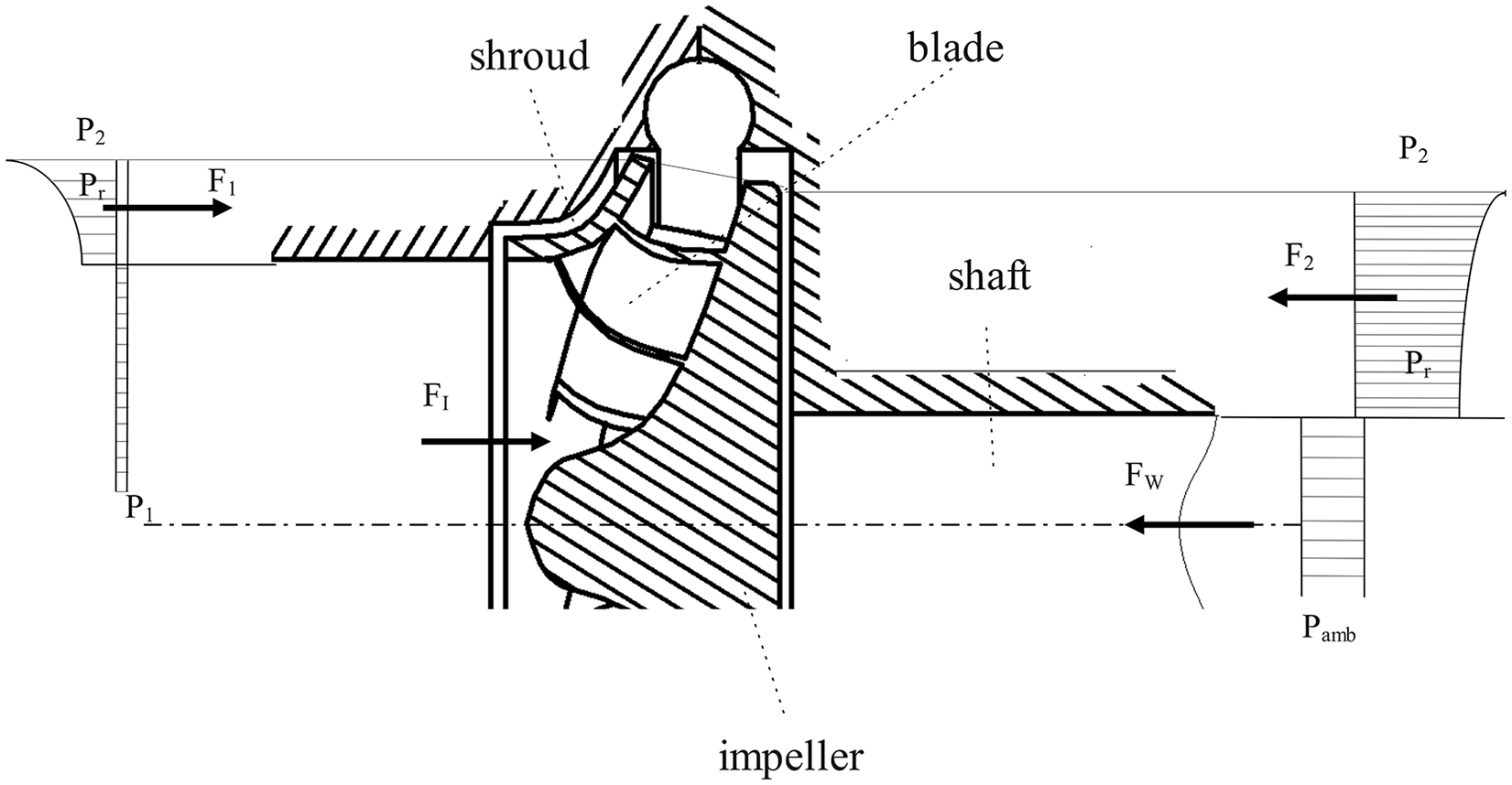
Pressure and forces acting on a pump impeller. (adapted from 9 )
Magnetic levitation (maglev) blood pumps have been developed in various institutes due to their high durability, low hemolytic index rates, and anti-thrombogenic properties. 10 The impeller in many advanced rotary blood pumps that can be used for long periods remains in a levitated position in its volute by magnetic or hydrodynamic systems. The hydrodynamic bearings operating at low clearances can cause increased blood damage and also have high energy consumption as they resist high forces. 11 In the design of such levitation systems, the forces acting on the impeller should be determined carefully. The radial forces cause vibration during the operation of a centrifugal pump and reduce pump life. The reason why the centrifugal heart pump generates a large radial force during its operation is the complexity of the internal flow and the asymmetrical of the volute geometry. 12
One of the motivations of this study is to investigate the effect of hydraulic forces acting on the blood pump impeller on the hydraulic and hemolytic performance of the pump. In this context, four impellers with different bearing properties have been designed and their performance has been determined via CFD. Another motivation for this study is to understand how the hydraulic and hemolytic performance of the pumps with viscosity change. Additionally, the wall shear stresses of the pumps have been explored at variable flow rates. The contributions of this study can be summarized as follows.
It presents a detailed calculation and evaluation of the radial and axial forces acting on the pump impeller.
It reveals comparatively the changes in the hydraulic forces and hydraulic efficiency of the blood pump due to the change in the viscosity of the working fluid.
It evaluates a detailed investigation of the wall shear stresses which is a critical parameter for the hydraulic and hemolytic performance of blood pumps for the mixed-flow pump.
It compares the hydraulic forces, wall shear stresses, and hydraulic efficiency in pumps with 4 different impellers in terms of bearing.
The rest of this paper is planned as follows. In Section 2, we present a design methodology for the pumps. Additionally, the CFD simulation technique is considered. The results are presented and the performance of the pumps are compared in Section 3. In the end, conclusions are given in Section 4.
Method of design and simulation
This section proposes a methodology for CFD-based force investigation in blood pumps. we describe the designed blood pump with different impellers. Then, we present the design detail of the volute. As a final step, we define the blood pumps’ CFD-based hydraulic force and efficiency determination method by explaining the meshing, flow simulation, and governing equations subsections.
Design of impellers and the volute
The design method of the pump and volute is based on Gülich 9 and Baysal 13 Additionally, ANSYS Bladegen and CFturbo software made use of the pump design. Figure 2 shows the configuration of the designed impellers. The design parameters of the pump are 5 L/min., 8000 rpm, and 100 mm Hg. These pumps have 12 mm inlet diameter, 16 mm outlet diameter, and 2 mm outlet width. The impeller-b (shaftless and outer grooved impeller) has six grooves that model in a 25° angle and 0.1 mm outer thickness. The impeller-c (shafted and grooveless impeller) has a hydrodynamic shaft that is 12 mm in length and 4 mm in diameter. The impeller-d (shafted and inner grooved impeller) has six grooves (30° angles and an inner depth of 0.2 mm) with a thickness of 2.5 mm.
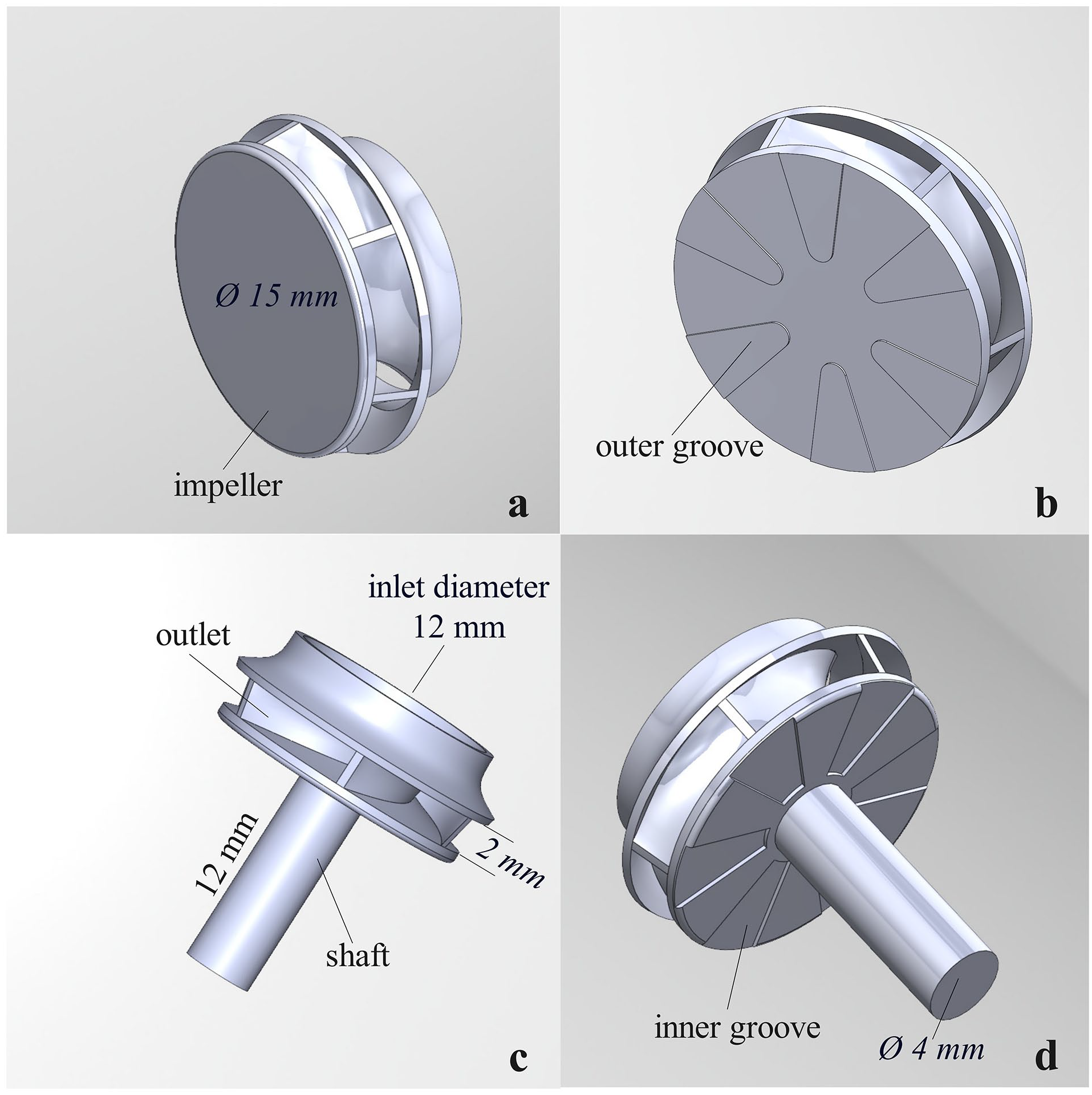
Designed impellers: (a) shaftless and grooveless impeller, (b) shaftless and outer grooved impeller, (c) shafted and grooveless impeller, and (d) shafted and inner grooved impeller.
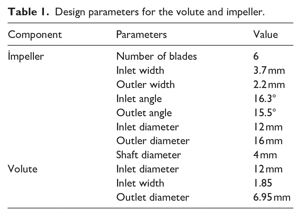
The volute in which the impellers operate has an inlet diameter of 12 mm, an outlet diameter of 6.96 mm, and an inlet width of 2 mm. Figure 3 shows the volute and impeller assembly fluid domains. Table 1 shows the design parameters of the impeller and volute.
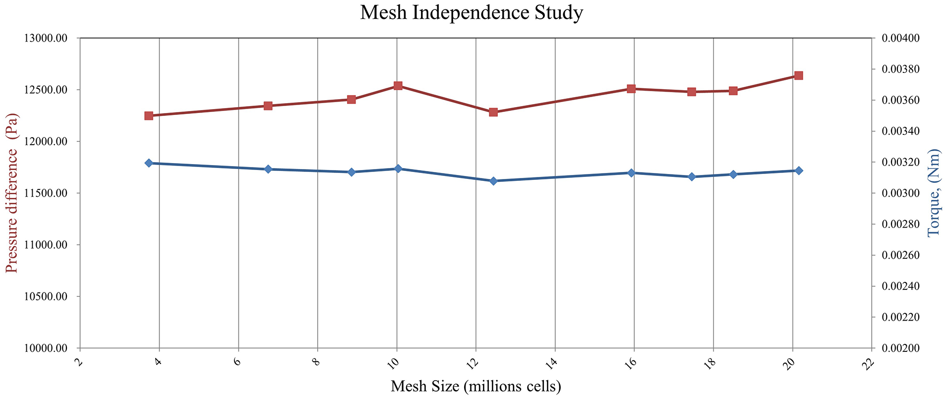
Influence of the number of elements on the torque and pressure difference.
Design parameters for the volute and impeller.
Pre-simulation modeling and meshing
The designed 3D pump models are imported into the ANSYS-Fluent packet software. After filling the fluid in the Design Modeler module, the mesh (number of cells) is created for the pump (Figure 3). By performing the mesh independence test, the number of cells is tuned as 17.3 million. In CFD studies of blood pumps, hydraulic efficiency, torque, and pressure difference parameters are generally examined in the mesh independence tests.3,14,15 It is observed that the torque and pressure difference parameters changed very little after this cell number. Therefore, simulation studies have been carried out with this mesh. Figure 3 shows the change in the pressure difference and torque parameters with the number of cells. Also, Figure 4 shows the pump meshed with impeller-a.
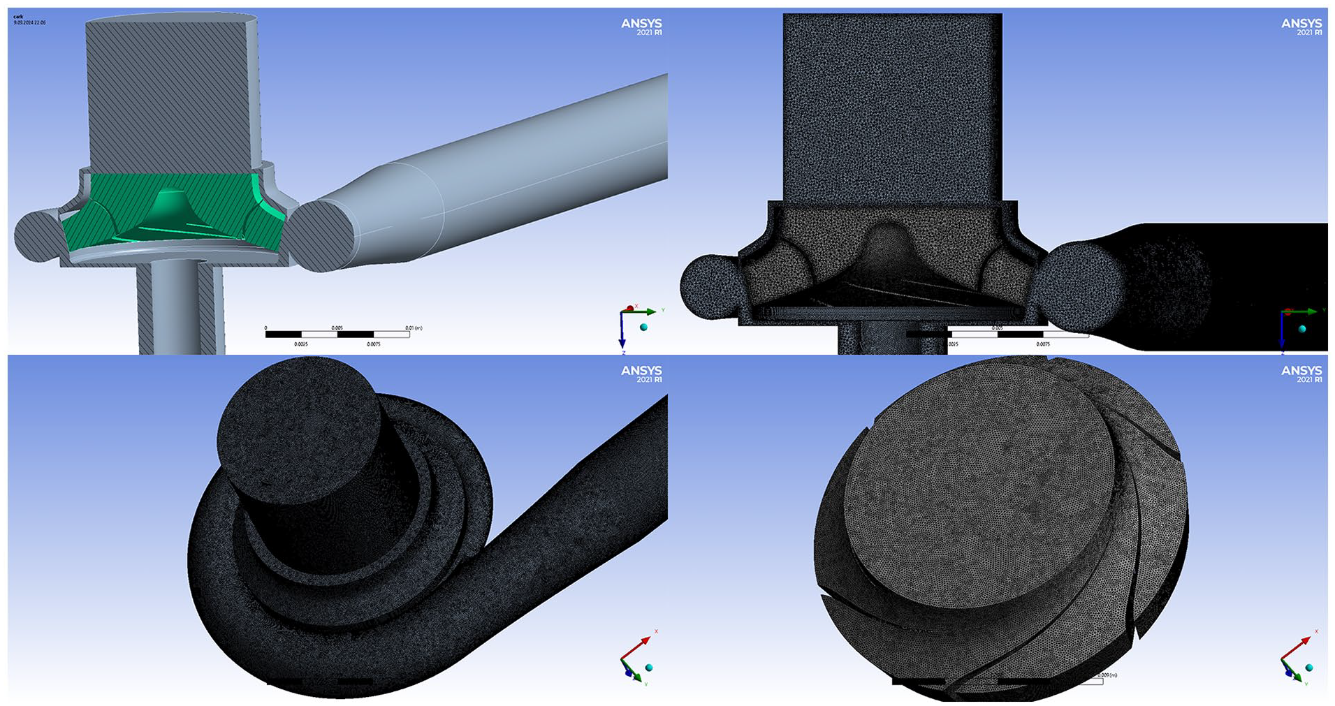
The mesh and flow domains of the pump with impeller-a.
Before the CFD setup section, the inlet and outlet surfaces of the pump and the surfaces on which hydraulic forces act are defined in the meshing section. Figure 5 shows the forces acting on the impeller. These forces are divided into axial and radial. Axial hydraulic forces act in the z direction, and radial forces act in the x and y directions. In this study, the radial forces acting on the hydrodynamic shaft are not considered because they do not have a significant effect.
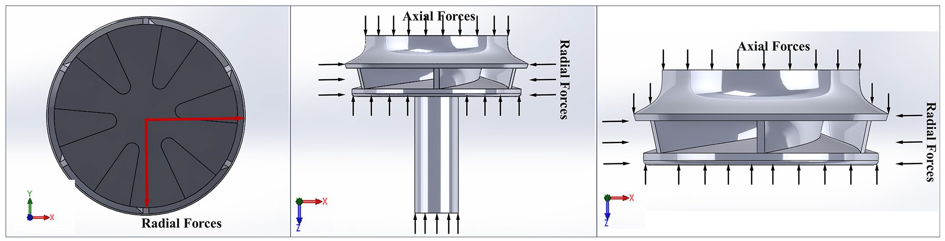
Forces acting on the impeller.
Flow simulation of pumps
The CFD simulations of the pumps have been executed with blood-like fluid in the ANSYS-2021 Fluent packet program. In the first simulation studies, the fluid viscosity is 3.5 cP and the density is 1050 kg/m3. In CFD simulation studies of blood pumps, the working fluid density is used between 1040 and 1080 kg/m3.1,16,17 However, we know that the density of human blood may change very slightly due to some pathological diseases. In this study, the density of the working fluid has been kept constant at 1050 kg/m3. On the other hand, the viscosity change has been considered in the simulations for four pump types. Generally, the dynamic viscosity of human blood can vary between 3.23 and 4.2 Cp at 37°C. For this reason, this study has examined each pump’s hydraulic forces and efficiency at fluid viscosity values of 3.25, 3.5, 3.8, and 4.25 cP. SST-k-ω turbulence model has been selected in the CFD simulations. The turbulence intensity is set to 4% and the hydraulic diameters are set to 12 and 6.96 mm at the inlet and outlet, respectively. The coupled scheme has been used as the discretization scheme. The convergence criterion of the simulations has been tuned as 10−5.
Governing equations in the CFD simulations
In the CFD simulation, Fluent solves continuity, momentum, and energy equations in all finite volumes. The continuity equation is the equation also called the mass conservation equation. The net mass transfer into and out of a time-varying closed system is equal to the net mass change (increase or decrease) within the system over time. 18 The momentum equation states that the gradient of momentum of a fluid particle is equal to the sum of the forces acting on the fluid particle (Newton’s second law). Two types of forces act on fluid particles. Surface forces: pressure force, viscous force; Body forces: gravitational force. centrifugal force, coriolis force, and electromagnetic force. The change in energy of a fluid in a certain time is equal to the energy released by heat, work, and mass per unit of time. The energy can be transformed into different forms. 18 The simulations were solved with the energy equation closed.
Continuity equation
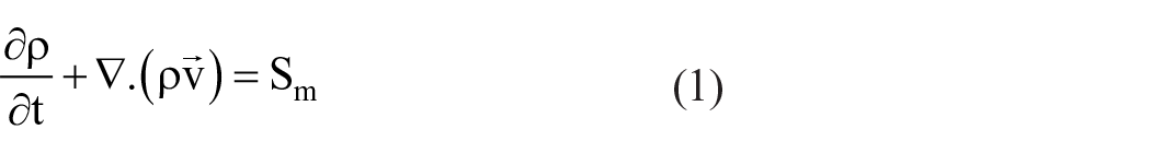
Where, Sm, t, and ρ states the source term, time, and density, respectively. 19
2. Navier-Stokes equations: Momentum Conservation Equations
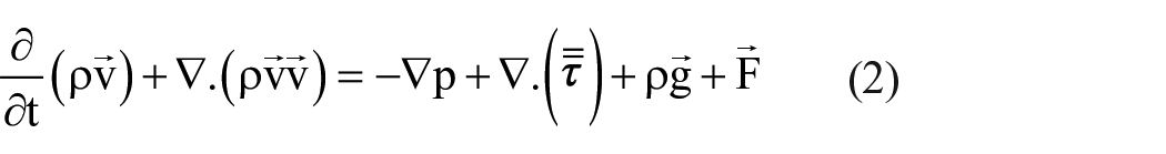
Where, P,
3. Energy conservation equation
Depending on the problem coped with, ANSYS Fluent solves the energy equation which will consider the heat transfer methods that will be specified. Equation (3) is the energy equation solved by ANSYS Fluent.
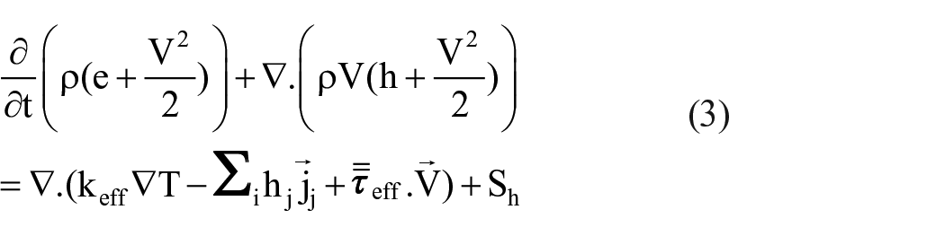
Where, h, T, and
SST k-ω turbulence model
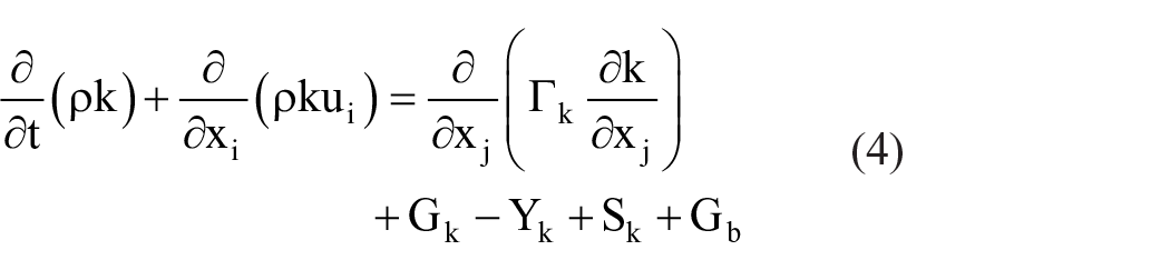
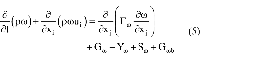
The standard k-ω model contains a k-ω model proposed by Wilcox that includes modifications for low Reynolds number effects, compressibility, and wall shear flow dissipation. The standard k-ω model is an empirical model based on transport equation models for turbulent kinetic energy (k) and specific dispersion velocity (ω). Turbulence kinetic energy (k) and specific dispersion velocity (ω) are obtained from the transport equations with the following equations (4) and (5). Modifications to the BSL k-ω model are incorporated into the SST k-ω model and also account for the turbulent transport of shear stresses in turbulent viscosity modeling. These features of the SST k-w model show its accuracy and reliability for a wider flow class than the standard and BSL k-w models. 20
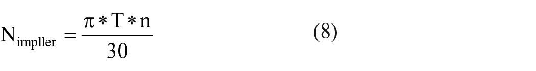
The hydraulic efficiency and the hydraulic forces of all pumps have been calculated using the results obtained from the Fluent simulations. Equation (6) calculates the pump pressure difference. Equations (7) and (8) calculate fluid and impeller power, respectively. Here


Results and discussion
In the preliminary design studies of blood pumps; geometric optimization problems to increase the hydraulic efficiency of the pumps, reduce the hemolysis index causing blood damage, prevent blood clotting in the pump, and improve the flow in the pump are current research topics that need to be considered.21–23 The forces acting on the pump impeller, shear stresses, and fluid viscosity play an important role in these research issues. This study investigates hydraulic forces, shear stresses, and viscosity changes in four different pump designs based on shaft and groove types. The result of the study shows that the pump without a groove generates lower hydraulic forces. It also reveals the effect of viscosity variations on pump performance. Therefore, the results of this study will contribute to future studies on the detection of damage to the blood in the pump, the effect of pump geometry on hydraulic forces, hydraulic efficiency improvement, and geometric optimization. By using the design techniques applied in our comparative study, efficiency and hemolysis index improvement studies can be carried out in other pump types such as axial and centrifugal in future studies.
Figure 6 shows the pressure differences between the inlet and outlet of the pumps in 1–6 L/min volumetric flow rates. At the design point (Q = 5 L/min, Hm = 100 mmHg, N = 8000 rpm), the pressures of the pumps have been obtained as 12,750 Pa (95,627 mmHg) for the pump-a, 12,548 Pa (94,113 mmHg) for the pump-c, 12,972 Pa (97,29 mmHg) for the pump-c, and finally 12,834 Pa (96,252 mmHg) for the pump-b. In the literature, the pressure difference of blood pumps with approximately the same rotation speed (8000 rpm) is between 90 and 120 mmHg.1,24
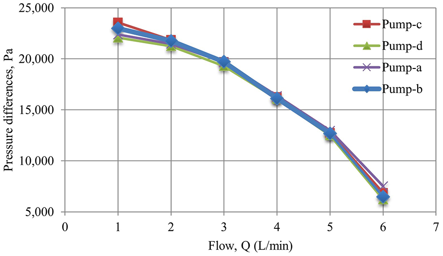
Pressure differences of pumps with different impellers
Figure 7 shows the static pressure distributions of the impellers and volute. The fluid enters the pump in the axial direction and exits through the volute. The pressure energy of the fluid from the inlet to the outlet is increased by the impeller. According to the pressure contours drawn for 8000 rpm and 5 L/min in Figure 7, the largest pressure difference occurs in the pump with type d.
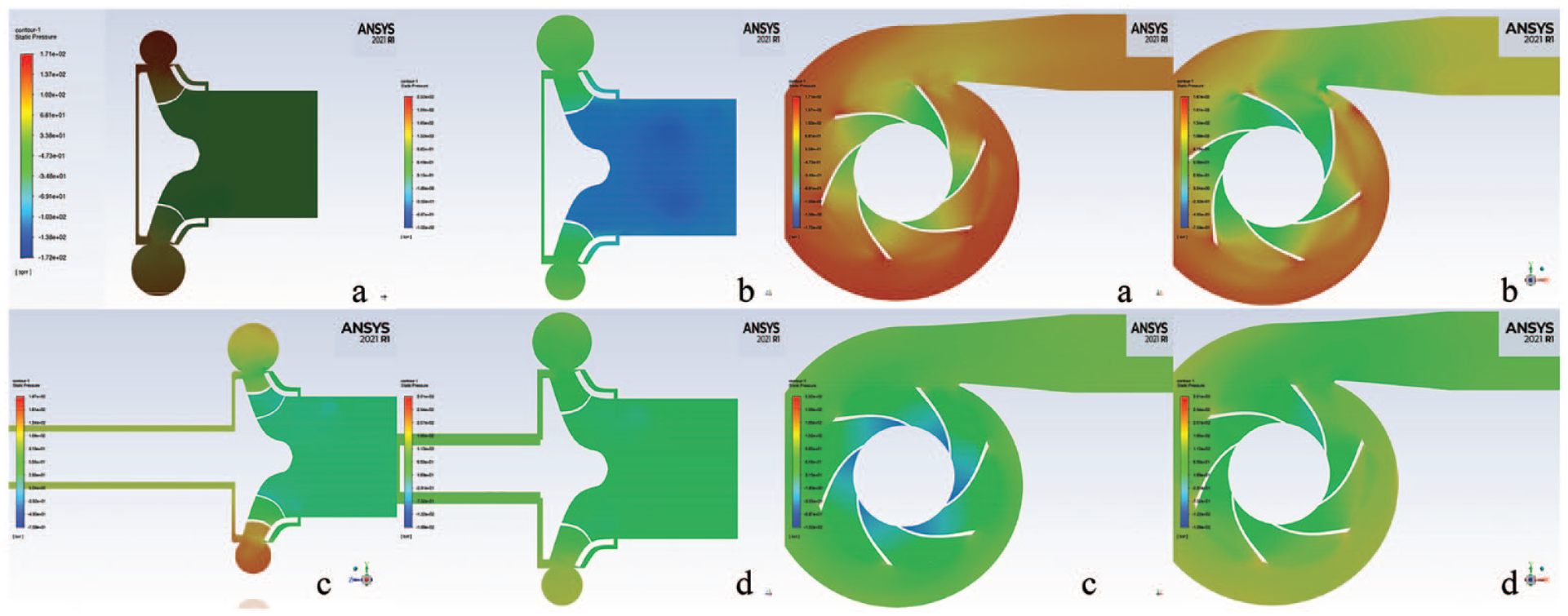
Static pressure of pumps. (a) Shaftless and grooveless impeller, (b) shaftless and outer grooved impeller, (c) shafted and grooveless impeller, and (d) shafted and inner grooved impeller (5 L/dak and 80,00 rpm).
Figure 8 shows the hydraulic efficiency changes of the pumps according to the volumetric flow rate. Accordingly, the maximum hydraulic efficiency is obtained with the pump-a and pump-c. However, the hydraulic efficiencies of these pumps are close to each other at all flow rates. The hydraulic efficiencies obtained at the design point are 39.5% for the pump-d; 37.07% for the pump-c; 40.87% for the pump-a; and 38.27% for the pump-b. In the literature, depending on the type and rotational speed of the blood pumps, their hydraulic efficiency varies between 25% and 50%.3,25
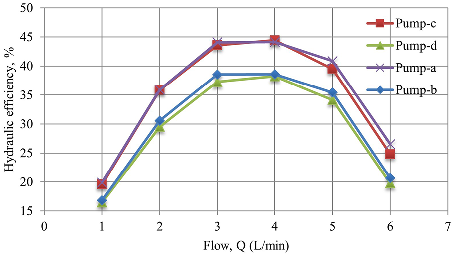
Hydraulic efficiencies of pumps: (a) shaftless and grooveless impeller, (b) shaftless and outer grooved impeller, (c) shafted and grooveless impeller, and (d) shafted and inner grooved impeller.
Figure 9 shows the streamlines inside the pumps. No flow irregularity was observed in the streamlines at the design point. In all pumps, only minor flow turbulence was noticed around the volute tongue. However, this turbulence did not have any effect on the performance of the pumps.
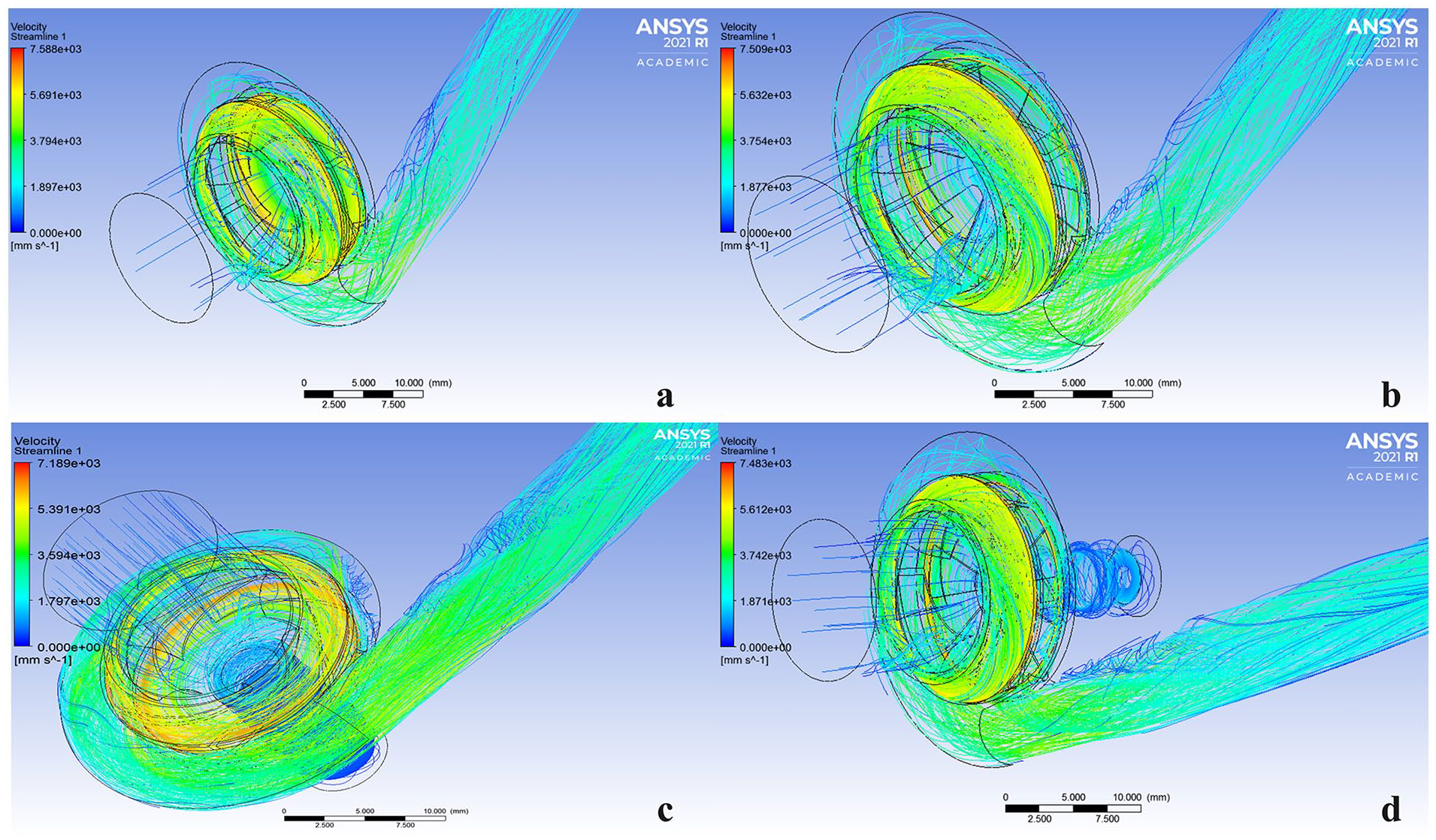
Velocity streamlines inside the pump for 5 L/min: (a) Shaftless and grooveless impeller, (b) shaftless and outer grooved impeller, (c) shafted and grooveless impeller, and (d) shafted and inner grooved impeller.
Axial forces act on the pump impellers in the z direction and radial forces act in the x and y directions. Figure 10 shows the variation of axial forces with flow rate for the pump types. Accordingly, it has been observed that the minimum axial force is for pump-d in all flow rates. Axial forces have been calculated at the design point; −1.67 N for the pump-a; −1.66 N for the pump-b, −1.85 N for the pump-d, and −1.78 N for the pump-b. Since the flow direction of the fluid is positive z, the calculated axial forces have negative values. In other words, these forces lift the pump upwards, preventing the impeller from hitting the volute. Compared to the literature, the axial forces are reasonable. For example, in the pump in Han et al., 26 axial forces vary between 0.6 and 1.8 N.
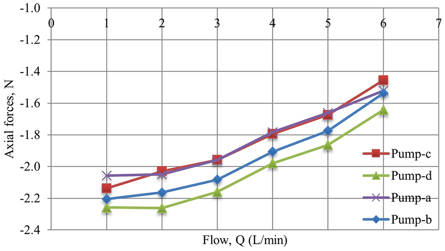
The axial forces acting on impellers: (a) shaftless and grooveless impeller, (b) shaftless and outer grooved impeller, (c) shafted and grooveless impeller, and (d) shafted and inner grooved impeller.
Figure 11 shows the change of radial forces acting on the impellers with flow rate. Accordingly, the radial forces of pump-b are greater than other pumps. The pump-d has minimum radial force. Figure 11 shows that the radial forces decrease with the increase in flow rate at low flow rates (1–3 L/min). On the other hand, the opposite situation occurs in the flow rate range of 3–6 L/min. It has been observed that the radial forces of pump-b are different from other pumps. The maximum radial force has been calculated as 0.124 N at a flow rate of 6 L/min in the pump-b. It is noticed that the minimum radial forces for all pump types have occurred at a 3 L/min flow rate. In Kannojiya et al., 1 the radial force acting on a centrifugal impeller varies between 0.4 and 1 N. Similarly, in Li et al., 17 the radial forces acting on the impeller vary between 0 and 1.5 N, and the radial forces decrease up to 4 L/min and then increase with increasing flow rate. In this study, radial forces initially decrease until the flow rate is 3 L/min and then increase with increasing flow rate.
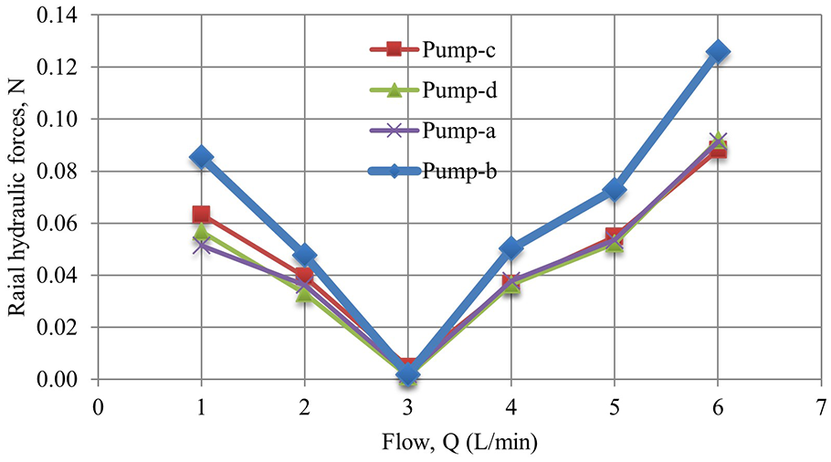
The radial forces acting on impellers: (a) shaftless and grooveless impeller, (b) shaftless and outer grooved impeller, (c) shafted and grooveless impeller, and (d) shafted and inner grooved impeller.
Velocity vectors of the fluid are important to understand whether the flow flows regularly or not. Figure 12 shows the velocity vectors inside four different pump types. The fluid flow direction is observed to be smooth in the high-speed regions and between the impeller and volute bodies in each pump. It is also determined that the velocity vectors created low vortices at the entrance of the impellers. Similarly, small vortices are observed to form on the shaft. It is thought that these irregularities are caused by flow turbulence on the shaft.
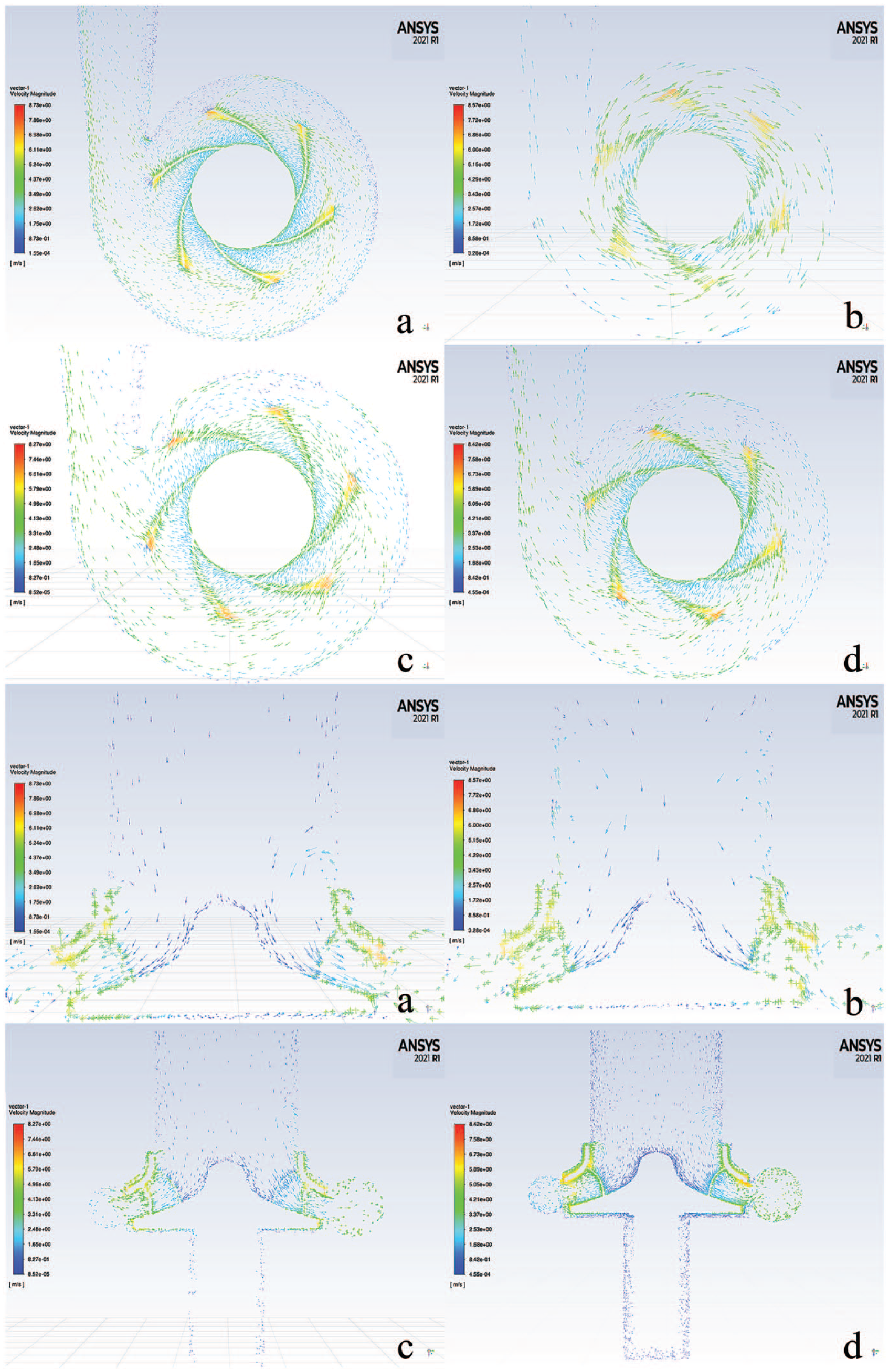
Pump velocity vectors for 5 L/min: (a) shaftless and grooveless impeller, (b) shaftless and outer grooved impeller, (c) shafted and grooveless impeller, and (d) shafted and inner grooved impeller.
The wall shear stresses within the pump play an important role in the hemolytic performance of blood pumps. 17 For this reason, the wall shear stresses occurring in the four blood pumps designed in this study have been examined with CFD. Figure 13 shows the change in the wall shear stress with the flow rate of these pumps. According to these results, the wall shear stresses decrease as the flow rate increases in the 1–2 L/min flow rate range. However, when the flow rate is greater than 2 L/min, the wall shear stresses increase as the flow rate increases. As seen in Figure 13, the wall shear stress values are very close to each other in the all-pump types. However, at high flow rates, the wall shear stresses of pump-b are greater than others. It is thought that the reason for this is that the blood flow rate around the wheel decreases and changes direction due to the narrow gap between the lower cover of the wheel and the volute (Figure 14).
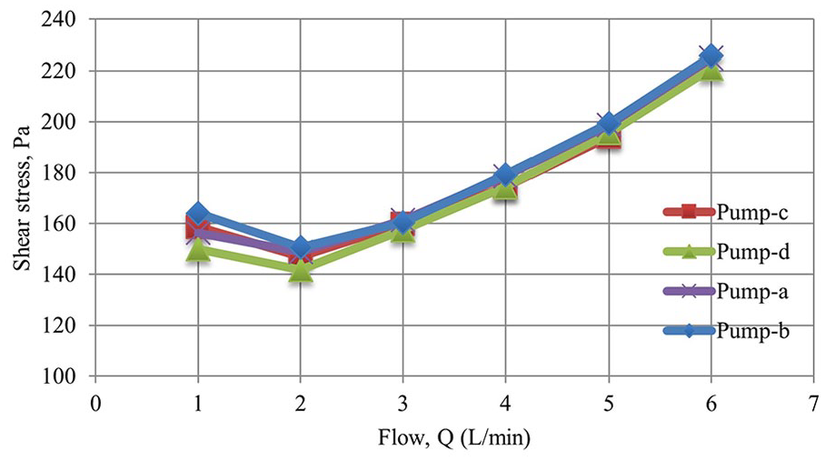
Wall shear stresses according to flow rate: (a) shaftless and grooveless impeller, (b) shaftless and outer grooved impeller, (c) shafted and grooveless impeller, and (d) shafted and inner grooved impeller.
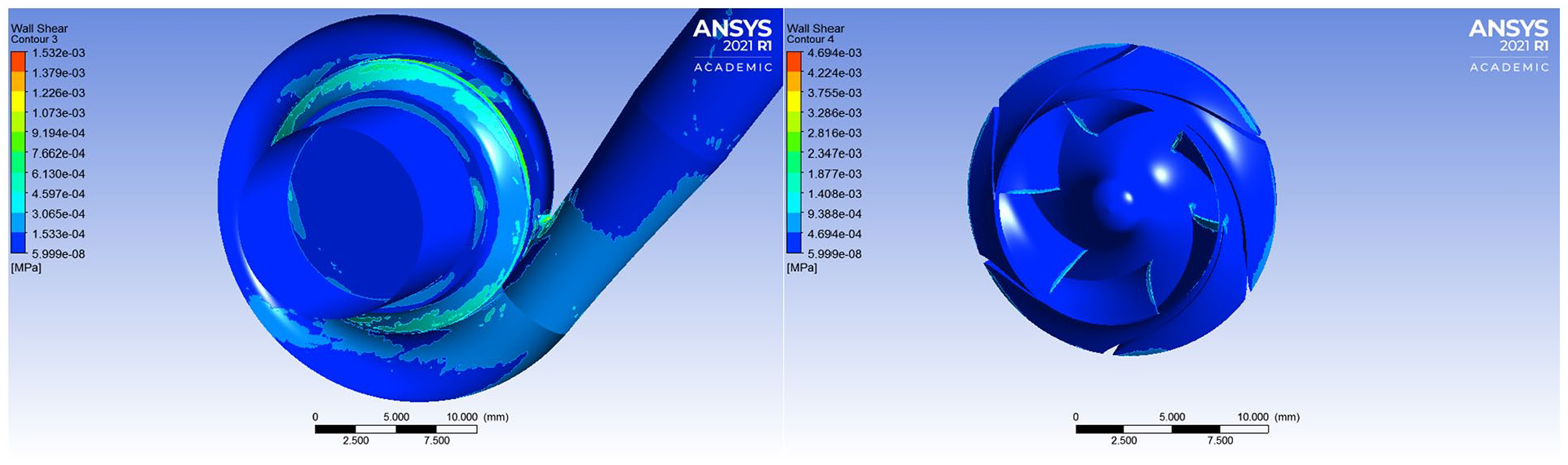
Wall Shear stresses of shaftless and outer grooved impeller (pump-a) for 5 L/min.
One of the important parameters to be considered in the design of blood pumps is the blood hemolysis index. For this reason, it is important to determine the shear stresses that affect the hemolysis index in the blood pump design process. In this study, shear stresses have been calculated in narrow channels in the flow domain (between the volute and impeller), at the inlet and ends of the impeller blades, at the inlet of the volute, and at the diffuser inlet regions for blood pumps designed in this study. Since these regions are important in terms of shear stress in previous studies conducted by the authors, the same areas have been especially investigated in this study. The shear stresses have been calculated separately for the pump impeller and the volute have been summed to determine the total shear stresses of the pumps for each flow rate. Figure 13 shows the wall shear stresses on the volute and impeller. The highest calculated wall shear stress value is 227 Pa. This value has been calculated in a shaftless pump with an outer grooved impeller (pump-b), at a flow rate of 6 L/min. Low hemolysis index (blood cell breakdown) occurs at low shear stress; Similarly, we know that a high hemolysis index occurs at high shear stress. The upper limit value used in blood pumps, based on the contact time of shear stresses, is 400 Pa. 27 In this study, shear stress values of less than 400 Pa were obtained for different impeller types examined.
The variation of hydraulic forces with viscosity has been investigated dynamic viscosities ranging from 3.23 × 10⁻³ to 4.20 × 10⁻³ Pa s since the viscosity of human blood varies in this range.28,29 Figure 15 shows the variation of axial force with viscosity. Accordingly, it was observed that the axial force increased with the increase in viscosity in pumps other than pump-b. Similarly, Figure 16 shows the change of radial forces, and it is observed that the radial force increased with the increase in viscosity.
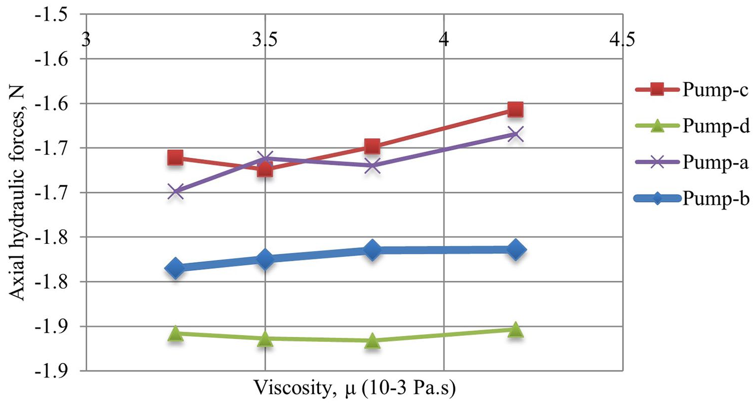
Viscosity versus axial hydraulic forces for 5 L/min: (a) shaftless and grooveless impeller, (b) shaftless and outer grooved impeller, (c) shafted and grooveless impeller, and (d) shafted and inner grooved impeller).
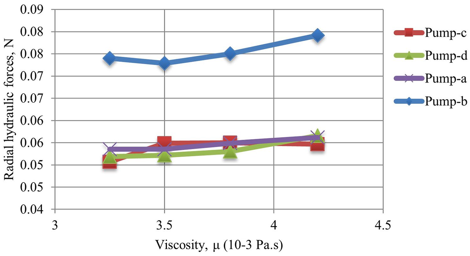
Viscosity versus radial hydraulic forces for 5 L/min: (a) shaftless and grooveless impeller, (b) shaftless and outer grooved impeller, (c) shafted and grooveless impeller, and (d) shafted and inner grooved impeller).
Figure 17 shows the variation of pump hydraulic efficiency with viscosity. Accordingly, it is seen that there is a slight decrease in hydraulic efficiency with the increase in viscosity. It can be said that the viscosity of fluid affects the hydraulic efficiency of the pump. It has been observed that the hydraulic efficiency of the pumps decreased by about 10 percent in the determined viscosity range.
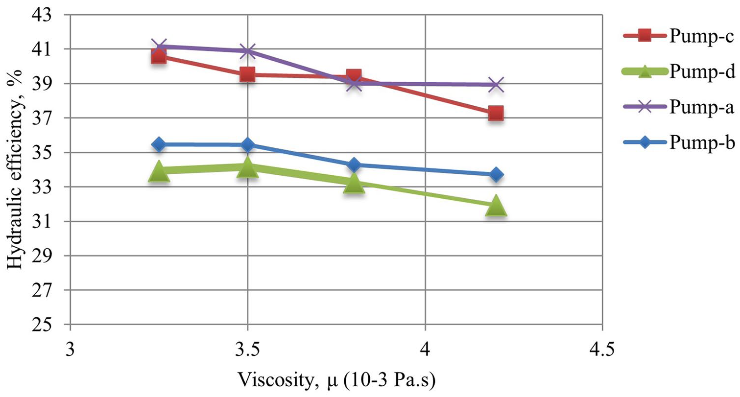
Viscosity versus hydraulic efficiency for 5 L/min: (a) shaftless and grooveless impeller, (b) shaftless and outer grooved impeller, (c) shafted and grooveless impeller, and (d) shafted and inner grooved impeller.
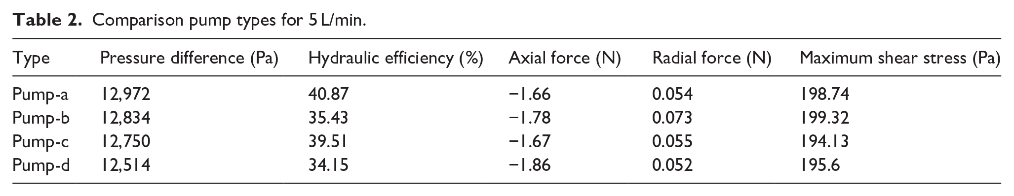
Table 2 shows a comparison of the pumps. In summary, the hydraulic and hemolytic performances of the designed pumps were compared to determine their convenience. Accordingly, hydraulic efficiencies for pump-a, pump-c, pump-b, and pump-d were calculated as 40.87%, 39.5%, 38.27%, and 37.07%, respectively. Also, the order of shear stresses is pump-b, pump-a, pump-d, and pump-c. High hydraulic efficiency and low shear stress are expected from blood pumps. In this context, it can be said that pump-c has the best performance.
Comparison pump types for 5 L/min.
Conclusions
The forces acting on blood pumps directly affect their hydraulic and hemolytic performance during design and operation. This study aims to examine the axial and radial forces acting on a mixed-flow blood pump via CFD. In this context, four types of impellers are designed and CFD simulations are carried out by placing these impellers in the same volute. The designed impellers are shaftless-grooveless (pump-a), shaftless-outer grooved (pump-b), shafted-grooveless (pump-c), and shafted-inner grooved (pump-d).
The hydraulic performances of these pumps and the acting axial and radial forces are determined via CFD. Also, the wall shear stresses, an important performance index for blood pumps, are examined. Finally, the variation of hydraulic efficiency and forces of these pumps with viscosity has been calculated with the help of Fluent.
According to the simulation results, it is observed that the hydraulic efficiency of the pumps varied between 30% and 45% in the flow rate range of 2–6 L/min. In addition, the pressure differences of the pumps vary between 8 and 24 kPa within the same flow rate range. The axial forces acting on the pump impellers are opposite to the direction of blood flow, and it has been observed that the largest axial force is in the pump-d. The radial forces are very small compared to the axial forces, and the largest radial force is seen in the pump-b. The wall shear stresses in the pumps have been examined to determine the risk of fragmentation of blood cells. Accordingly, the maximum wall shear stress is in 6 L/min flow rate and its value has been calculated as 230 Pa for the pump-b. Considering that the upper limit of the wall shear stress is 400 Pa to prevent damage to blood cells, this result can be said to be reasonable.
It is thought that this study may be useful for blood pump designers. As a future study, the authors plan to perform a geometric optimization study that maximizes the hydraulic efficiency of the pump by considering the forces acting on this pump. Also, the groove design proposed in this study can be applied to other types of blood pumps to improve their hydrodynamic and hemolytic performance.
Footnotes
Acknowledgements
The authors are grateful to companies CFturbo GmbH and Desica for providing a trial license for the CFturbo software.
Declaration of conflicting interests
The author(s) declared no potential conflicts of interest with respect to the research, authorship, and/or publication of this article.
Funding
The author(s) received no financial support for the research, authorship, and/or publication of this article.
Ethical approval
The manuscript does not contain clinical studies or patient data.