
Abstract
Traction power consumption is an important part of energy consumption in railways. Many parameters, such as the geometric structure of the line, vehicle characteristics, and passenger density, affect the traction power consumption. Besides these parameters, the most important factor affecting the traction power consumption of a train is the speed profile of the train. Development of the speed profile has significant potential in energy efficiency. The objective of this study is to set an optimization model to minimize energy consumption and the size of the on-board energy storage device as much as possible, based on the appropriate train speed profile and recuperation of braking energy along the route, determined on a tram line with a ground-level energy supply system, and solving the optimization model by using a genetic algorithm (GA). In the study, a speed profile optimization is presented using GA. The objective function is to find the optimal maximum operation speed limit and speed profile that will reduce energy consumption and the on-board energy storage device size requirement within the specified running time based on operation expectations for each inter-station zone. In the mentioned speed profile optimization, constraints such as maximum and minimum running time for each inter-station zone, maximum operation speed limit for each inter-station zone, maximum acceleration and deceleration are taken into account. The simulation results show that energy savings for traction of up to 60% can be achieved compared with the existing system structure, with the usage of the recommended hybrid energy storage unit and optimized speed profile.
Keywords
Because of increase of demand day by day, the energy-efficiency problem is always on the agenda of the railway system industry, as it is for every other industry. For the solution of this problem, implementations such as increasing the use of renewable energy resources, using smart control systems, and using energy-saving products are energy policies that have spread throughout the world.
At the present time, the urban rail transportation systems plays an important role in urban mobility in modern and developing cities. Urban railway systems demand large amounts of energy and power. It is important to every institution to minimize the energy consumption to the lowest possible value. So, energy efficiency in railway systems is a popular research topic, with development and utilization of new technologies and algorithms about energy storage systems, reversible Direct Current (DC) traction power substation, reduction of braking losses, optimization of speed profile energy optimized timetables, and so forth.
Rail systems have a high potential to increase energy efficiency. In this direction, methods and applications such as speed profile optimization, train movement schedule optimization, use of energy storage units, reversible transformer centers, energy-efficient traction systems, reduction of the energy consumption of comfort functions, and smart energy management are used with the principle of reducing energy consumption and recovering braking energy ( 1 ).
The ground-level traction power supply system, which was developed as an alternative to overhead catenary systems to eliminate the environmental effects of traction power transmission systems, has the disadvantage of not being able to return the braking energy to the traction power transmission line. In this study, the aim is to find a solution to the serious energy inefficiency that arises because of the disadvantage of the ground-level traction power supply system, by optimizing the speed profile and using an on-board energy-storage unit with a suitable structure.
Tram lines using a ground-level traction power supply system have a disadvantage of not being able to return braking energy to the traction power transmission line. It is important to eliminate this disadvantage so that tram vehicles can perform better in energy efficiency and effectiveness. This study offers a suggestion that eliminates the relevant disadvantage via a proposed optimization and energy storage structure, and supports this with a real case study.
Railway Systems
Dynamic braking of electric vehicles temporarily converts kinetic energy into electrical energy by means of traction motors that work like generators during braking. The braking energy recovered in rail systems can be burned in on-board braking resistors or can support the power demand of vehicles in the same area. In recent years, with the development of technology, different methods, such as reversible transformer centers, increasing receptivity in the line, and stationary or on-board energy storage units, have been applied to benefit from braking energy.
Recovery of braking energy can significantly reduce total energy consumption in rail systems ( 2 ). There are many acceleration and deceleration phases on tram lines because of the structurally frequent stopping points, and this makes the recovery of braking energy an effective method in energy efficiency ( 1 ).
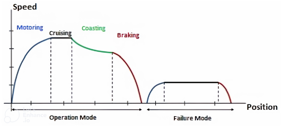
The movement of the rail system vehicle from one point to another is defined in four motion modes—motoring, cruising, coasting, and braking—based on traction and braking force ( 3 ). The driving modes used during the train’s movement from one station to another on a tram line are shown graphically in Figure 1 as a velocity-time curve and can be explained as follows.
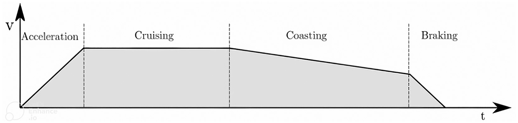
Train driving modes ( 3 ).
One of the effective methods for solving energy efficiency problems in tram lines is the use of on-board energy storage units. In this way, it is possible to increase the efficiency of the recovery of the braking energy and prevent the braking energy from being wasted on the braking resistors. On-board energy storage units can be a battery, supercapacitor, or hybrid storage system consisting of a battery and supercapacitor combination ( 4 , 5 ). The following benefits can be achieved with the use of on-board energy storage units on tram lines:
Decreased peak power demand in the supply line during the acceleration phase ( 6 )
Voltage stabilization and more frequent train operation ( 6 )
Backup energy source in emergencies and unexpected stops ( 6 )
Increasing energy efficiency by recovering braking energy ( 6 )
A Ragone chart, which compares the performance of energy storage units in power density and energy density, is presented in Figure 2.
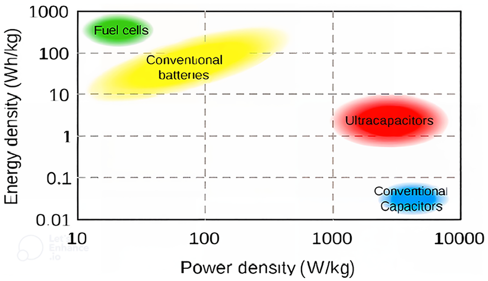
Energy storage units a Ragone chart ( 5 ).
Traction power transmission systems may differ according to the structural features and system requirements in the past and today in the metro, light rail, and tram lines that make up the urban rail transportation systems. Traction power transmission systems used in urban rail systems around the world are as follows:
Conventional overhead catenary system
Rigid catenary system
Third rail system
Ground-level traction power supply system
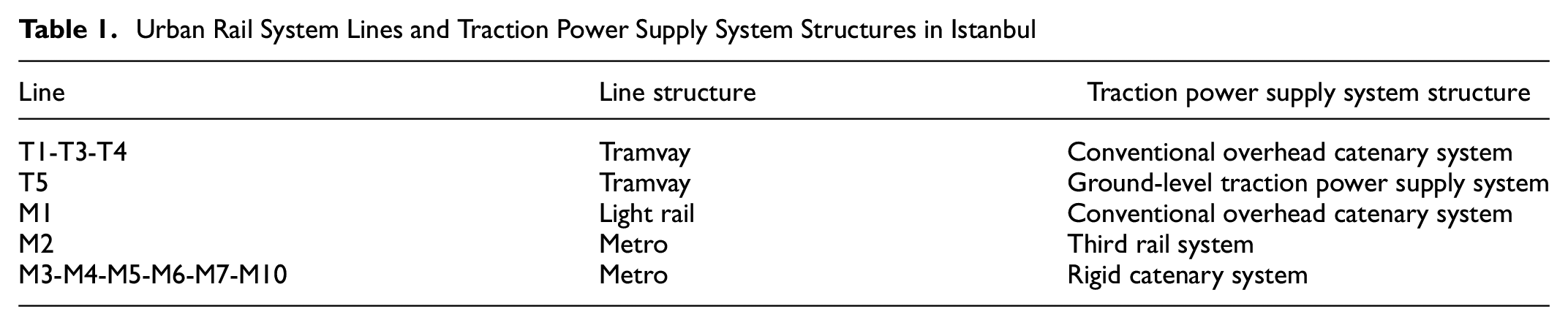
The most common system used in traction power transmission in tram lines is the conventional overhead catenary system. Conventional overhead catenary systems have negative effects in city centers or historical places, including visual pollution and physical effects. To eliminate these negative effects, ground-level traction power supply systems have been preferred recently. The application of each of the above-mentioned traction power transmission systems, which are used worldwide, can be seen in the urban rail systems in Istanbul in Turkey. The urban rail system lines in Istanbul and the traction power transmission systems used are given in Table 1.
Urban Rail System Lines and Traction Power Supply System Structures in Istanbul
In this study, the aim is to determine the optimal speed profile that will keep the total energy consumption and the braking energy recovery potential, which determines the on-board energy storage unit size requirement, as low as possible within the scope of determining the maximum speed limit and the transition points between the train operating modes.
Ground-Level Traction Power Supply System
One of the ground-level traction power supply systems that has been used in the world is Alstom’s “alimentation par le sol” (APS) system. This system is designed to provide traction power to the train by a power rail positioned between the running rails. The train array provides energy by using current collector shoes located in the middle section under the vehicles. The energy supply is provided by the physical contact between the current collector shoes and the power rails positioned between the running rails ( 7 ).
Power rails are generally 11 m long, consisting of 8 m conductors and 3 m insulated parts. This means that the power rails along the line are sequentially lined up with 8 m of conductive parts separated by 3 m insulated segments. The 8 m conductor parts of the power rails can be shortened to 4 m along the line if there are structural requirements.
The current collector system, located under the vehicles and in the middle section of the train set, consists of two shoes with a distance of 3.2 m. With the conductive parts of the power rails not being shorter than 4 m and the presence of 3 m insulated parts between the two conductive parts, it is aimed to ensure continuous traction power supply by contacting at least one of the two current collector shoes on the vehicles with the conductive part of the power rail during the train movement.
The power supply rails are fed with 750 Volts Direct Current (VDC) by the power boxes located in the manholes embedded in the rail line between the two tracks. There are connections to the power boxes from the DC cables that provide 750 VDC energy transmission obtained with the electrical switchgear equipment in the traction power substation installed along the line, and the Zero Voltage Reference (0Vr) cable that is electrically connected to the running rails, which is also used as a negative return circuit in DC rail systems. In addition, the multi-functional cable, which performs functions such as the safety line that enables the control and command of the power boxes located on the line route from the control cabinets in the traction power substation, auxiliary power supply to the contactors and electronic components of the power boxes, and the detection of the problems in the system, is also connected to the power boxes sequentially.
The APS system operates on the principle that the conductive parts of the power supply rails are energized only if they are completely covered by the tram vehicle. With this principle, it is ensured that energized parts are never accessible to passengers or other living things. The antenna loop circuitry embedded around the power supply rails detects the presence of the train by means of a coded radio signal emitted by the tram vehicle. The power box detecting the presence of the train energizes the conductive part of the corresponding power supply rail with 750 VDC. If there is no vehicle presence in the area, the conductive part of the power supply rail is connected to the 0Vr cable via the power box. The general structure of the APS system is shown in Figure 3.
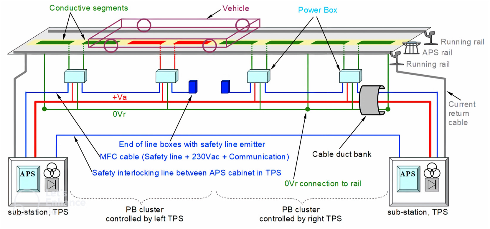
“Alimentation par le sol” (APS) system structure.
Literature Review
With the rising demand for urban rail transportation systems, energy and environmental sustainability attracts great attention in the rail transportation sector, as well as in every sector. The rail transportation systems, which are one of the public transportation systems with the least CO2 emissions, have a much more environmentally friendly structure than many other transportation modes; nonetheless, energy efficiency in rail transportation systems is still the focus of attention in the sector. Institutions and organizations that operate or construct rail transportation systems are trying to ensure energy efficiency through different operational applications or technological equipment in line with both environmental and financial concerns. Many applications aiming at energy efficiency are encountered in the world. Although these applications are structural or vehicle specific, they are also made with a whole-system approach ( 8 ). The main energy saving actions in urban rail transportation systems are grouped according to the application method and scope in Figure 4.
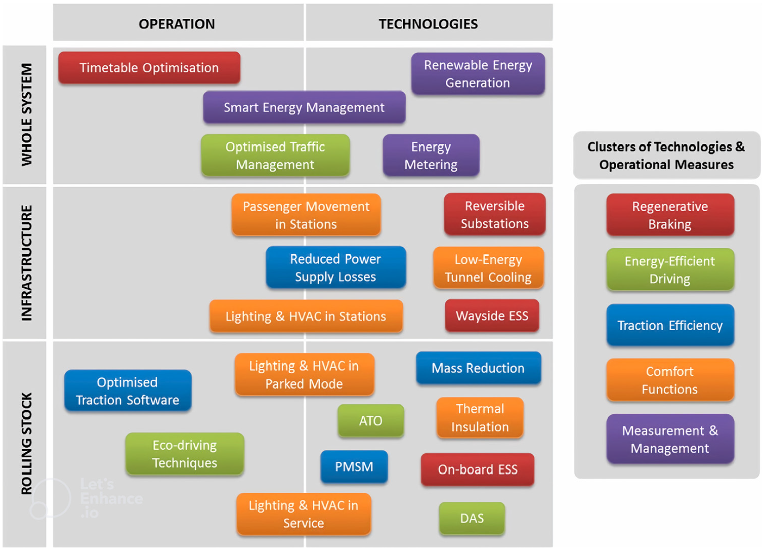
Basic actions for energy saving in urban rail systems ( 8 ).
In the practical analysis of energy-saving measures in urban rail systems, their suitability is evaluated according to two basic criteria. Technically, the applicability indicator is determined with the energy saving potential and investment cost criteria. Technical applicability indicators differ according to the problems that will be encountered in the case of the implementation of the energy saving measures in real systems ( 8 ). Comparison of the energy saving application according to energy saving potential and investment cost for urban rail transportation systems is shown in Figure 5.
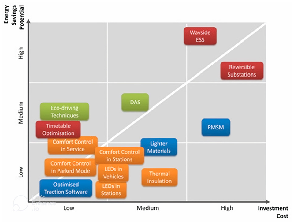
Comparison of energy efficiency measures for existing urban rail systems ( 8 ).
Studies show that approximately 40% of the energy consumed by a train can be provided by the recuperation of braking energy. For the recuperation of braking energy, technological applications such as reversible substation installation and use of energy storage units and operational applications such as speed profile optimization and synchronization of train schedule have been proposed. The use of energy storage units is one of the most popular methods ( 9 ).
The use of energy storage units reduces peak power demands along with reducing energy consumption ( 9 ). Applications for the use of energy storage units in railway systems are classified into two main types: fixed storage applications called “wayside” energy storage units and mobile energy storage applications called “on-board” energy storage units ( 10 ).
In situations where it is aimed to maximize braking energy recovery, the use of supercapacitors with large power density and high charge/discharge cycle number is more appropriate than conventional batteries with a limited number of charge/discharge cycles ( 12 ). Batteries have a higher energy density compared with supercapacitors, while supercapacitors have a higher power density. The use of a hybrid energy storage unit structure in the form of a combination of these two technologies extends the life of the energy storage unit in the battery structure ( 5 ). As described by Graber et al., in an urban railway system with and without catenary regions, supercapacitors enable recuperation and utilization of the braking energy in acceleration and braking movements with high power density, and reduce peak power consumption, and lithium batteries provide back-up traction power, within some constraints, for catenary-free regions with high energy density ( 5 ). Therefore, the usage of a hybrid energy storage system consisting of a lithium battery and supercapacitor combination and an energy management strategy is proposed. In automotive applications, similar to rail systems, supercapacitors are suitable in train motion modes that require high power not exceeding a few seconds because of the low amount of energy required and, as for that, batteries are suitable for providing low-power vehicle autonomy ( 13 ).
Energy-efficient train operation using train motion modes will provide significant energy savings, especially when braking energy cannot be transmitted to other vehicles on the line ( 6 ). Instead of changing the existing railway system structure, in most studies, energy-efficient train operation and the usage of energy storage devices are discussed as ways to minimize traction consumption ( 14 ). Optimizing train speed control is a traditional way of saving traction power consumption and is usually achieved by seeking the optimal speed profile ( 14 , 15 ). One way to find this optimal speed profile is to find the optimal switching point for each transition between motion modes. Once the switching points are found, the entire speed profile can be obtained. The optimal train speed trajectory can be found by the maximum principle based on optimal control theory ( 15 ). The theory of optimal control between two stations based on the maximum principle consists of acceleration with maximum traction force, cruising, coasting, and braking with maximum deceleration ( 14 ). Systems such as the driver advisory system are used to provide optimal driving controls to drivers to arrive at the next station on time by calculating the best speed profile to reduce operating costs, improve energy efficiency, and improve train timetable regulation ( 6 , 16 ).
In Tian et al., considering the energy consumption and travel time, the “brute force” algorithm is used to solve the optimization problem and 10%–20% energy savings are achieved with the optimized speed profile in which the coasting phase is maximized and the optimal speed limits are determined ( 16 ). In Sumpavakup et al., it was aimed to balance the peak power with the recovery and reuse of braking energy by using the on-board energy storage unit in the supercapacitor structure, because of its characteristics such as fast charging and discharging capabilities, high power density, long life cycles, and low internal resistance ( 17 ). Reduction in energy consumption of 15.56% was achieved by optimizing the speed profile with a genetic algorithm (GA) within the transition to coasting and braking modes times control. In Gallo et al., traction power savings of 25% were achieved by optimizing the maximum speed for each section between stations, taking into account the energy consumption and travel time ( 18 ).
The most common ground-level traction power supply system is the APS system. The APS system was first used in 2003 in Bordeaux, France, for a 14 km catenary-free operation ( 16 , 17 ). It is used in 11 cities around the world. There is a single line application of approximately 150 km. The newest of these is the Istanbul T5 tram line, which started operating with passengers in 2021. In the Istanbul T5 tram line, as seen in the Dubai and Lusail tram lines, traction power is provided along the entire line with the APS system. In the Istanbul T5 tram line, valve-regulated lead acid batteries are used as on-board energy storage units for a back-up traction power source, under limited conditions.
The Paris T3 tram line has high receptivity in the use of braking energy. With the STEEM project, a supercapacitor was used as an on-board energy storage unit on the T3 line, which consists of overhead catenary line of 7.9 km and a catenary-free zone of 300 m. With high line reception, the energy storage unit size requirement will be reduced ( 19 ). In Nice, one of the places where the use of on-board energy storage units is seen, nickel–metal hydride (NiMH) battery technology was used for two square areas where approximately 450 m of catenary-free operation is applied ( 19 ). Alstom uses NiMH batteries as energy storage units, together with a ground-level traction power supply system, in Citidas vehicles ( 20 ).
Evolutionary algorithms are widely used in rail systems because of their complexity, nonlinearity, and uncertainty ( 21 ). Evolutionary algorithms are applied to obtain near-optimal solutions with reduced computation time ( 22 ). One of the typical evolutionary algorithms is the GA and it is one of the most common evolutionary algorithms used in rail systems ( 21 , 22 ). Achieving optimum speed profile and energy storage in rail networks is a difficult task. Optimization of the train speed profile of the rail system network under various constraints is a nonlinear problem. This makes it difficult to find the optimal train speed profile and indicates that the problem is NP-hard ( 22 , 23 ). One of the most important factors affecting traction power consumption is the train mass. Speed profile optimization is a difficult and nonlinear problem. The effect of the optimized energy storage unit on the total train mass has made this problem even more difficult.
Evolutionary algorithms such as the GA have shown high performance in solving complex and nonlinear problems ( 23 ). Nallaperuma et al. investigate optimizing optimal train control and energy storage to reduce energy consumption—the UK Merseyrail network was addressed and, by proposing a GA-based approach, a significant improvement in energy consumption of 15% to 30% was achieved ( 23 ). Li and Lo used GA to solve an optimization model aiming at minimizing net energy by utilizing regenerative braking and velocity trajectory optimization ( 24 ).
In the literature review, general preliminary information was given about the proposed method, within the scope of speed profile optimization and usage of on-board energy storage units to increase energy efficiency on a tram line using a ground-level traction power transmission system, by referring briefly to energy-saving applications in urban rail systems, braking energy recovery methods, energy storage technologies, speed profile optimization applications, algorithms used in similar problems, and ground-level traction power supply system application examples.
Mathematical Modeling of Train Movement
The movement of rail vehicles is determined by several physical limits, such as track path geometry, speed limit, and other vehicle-related factors. The forces acting on a rail system vehicle in the ramp area are shown in Figure 6. Traction force applied to a vehicle is used for the movement of the train against friction force and gravitational forces ( 17 , 25 , 26 ).
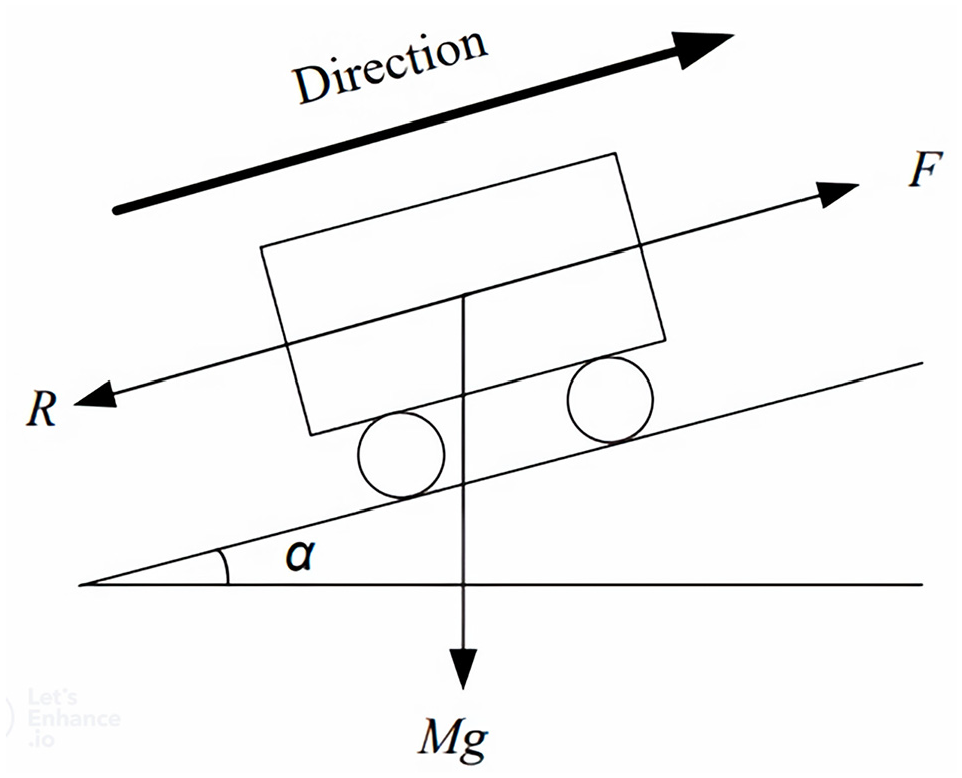
Forces acting on the rail system vehicle ( 21 ).
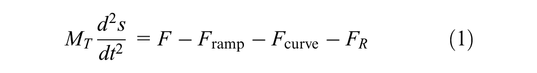
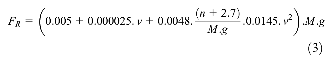
Train motion can be described by standard Newtonian equations of motion. Traction power, slope, and vehicle resistance control vehicle movement in the longitudinal direction. Equation 1, known as the Lomonossoff equation, is the equation of a train’s motion ( 17 , 25 , 26 ). Equation 2 is the mass equation covering vehicle tare weight, passenger load, and the effect of inertia moment. Equation 3, known as the Sauthoff equation, allows us to obtain the mass dependent rolling resistance ( 27 ). Equations 4 and 5 express other resistance values affecting the train resistance, and Equation 6 defines the total train resistance value.


where
M = the tare and passenger weight of the vehicle,
v = the instantaneous speed of the vehicle,
n = the number of sequences in the train,
g = the gravitational acceleration,
The traction force is generated by the traction motors and overcomes the forces acting in the opposite direction of the vehicle’s motion. The traction force curve defines the relationship between the traction force and the train speed. In the BS-EN50641 Railway Application—Fixed Installations Standard, the sample traction power curve of a train set at nominal voltage is specified. In this traction force curve, the velocity-dependent maximum traction force is expressed in three sections ( 25 ).
Maximum traction force behavior according to BS-EN50641 is indicated in Figure 7.
Section 1 is characterized as the constant maximum traction force from the moment of departure until the vehicle reaches
Section 2 is characterized in such a way that the maximum traction force of the vehicle decreases by
Section 3 is characterized so that the maximum traction force of the vehicle decreases by


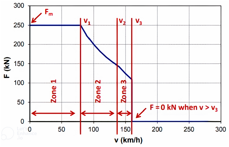
Typical traction force curve for a trainset at nominal voltage ( 27 ).
The maximum traction force and braking force graph of the vehicle considered in the study are given in Figure 8.
Maximum traction and braking force graph of the considered vehicle.
Train Driving Modes
Train movement is generally classified into four driving modes: motoring, cruising, coasting, and braking. Depending on the strategy to be applied, these movement modes can be seen in different arrays and orders in the movement cycle of a train. An example train movement cycle is shown in Figure 9, in which all four driving modes are seen.
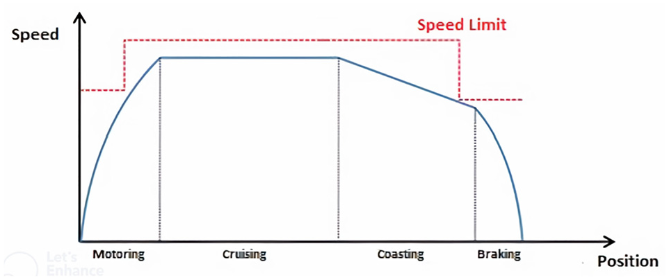
Example train movement cycle ( 30 ).
The motoring mode is generally used to increase the speed of the train during the departure time at the start of the journey. The traction force applied throughout the movement is greater than the sum of the resistance value acting on the train. In this drive mode, acceleration is positive. The mathematical equations related to the motoring mode are specified in Equations 10 and 11 ( 25 ).


The cruising mode is generally used to maintain speed in speed limitation areas. The traction force applied throughout the movement is equal to the sum of the resistance values acting on the train. In this drive mode, acceleration is zero. The mathematical equations related to the cruising mode are specified in Equations 12 and 13 ( 25 ).


The coasting mode is generally used where the train does not need traction power. The traction force applied throughout the movement is zero. It is defined as the energy-saving driving mode. The acceleration and deceleration are determined by the sum of the resistance values acting on the train. It can be seen that the train slows down in movements that create enough resistance against the direction of the train, such as up the ramp and on a straight road, and the train accelerates in downhill movements. Mathematical equations related to the coasting mode are specified in Equations 14 and 15 ( 25 ).


The braking mode is generally used when the train is approaching a stop or speed limit point. Both traction force applied throughout the movement and acceleration are negative. The mathematical equations related to the braking drive mode are specified in Equations 16 and 17 ( 25 ).


In this study, a single train simulation coded in Matlab software is applied. The energy consumption of the train, the recovered brake energy, and the running time are estimated by a single train simulation created in Matlab software. When the single-train simulation and operating data were compared, approximately 95% accuracy in energy consumption and 98% accuracy in running time was achieved. The optimization phase via GA, which will be mentioned in the later parts of this study, was performed by means of the optimization toolbox in Matlab.
Optimization
In the study, a speed profile optimization based on GA is presented. The objective function in GA is to find the optimal maximum speed limit and speed profile that will minimize the energy consumption and the on-board energy storage unit size requirement within the specified running time for each inter-station zone. In the mentioned speed profile, constraints such as maximum and minimum running time for each inter-station zone, maximum speed limit for each inter-station zone, maximum acceleration, and deceleration are taken into account.
While determining the optimal speed profile, the focus was on the transition points between the driving modes, from motoring mode to cruising mode, and from cruising mode to coasting mode. In addition to the two points mentioned, it was attempted to determine the most appropriate option for the maximum speed limit with GA. The GA will reach the most suitable transition points between driving modes and the maximum speed limit allowed in operation in accordance with the objective function. With the optimal solution obtained, the usage of the motoring mode will be postponed to areas close to the departure station, the use of the braking mode will be postponed to areas close to the stopping station, and the cruising and coasting modes usage phases will be extended as much as possible. In this way, while energy consumption will be minimized, the need for on-board energy storage will also be optimized.


t = index of time,
T = targeted running time between two departure movements of the train (s).
where
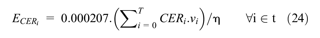
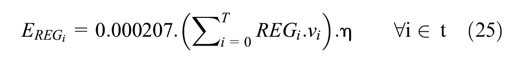
The traction and braking energy formula is specified in Equations 24 and 25 by using the force value obtained in the speed-dependent maximum traction power and braking power curve of the train, the energy conversion constant and power-energy conversion coefficients. Sampling frequency was taken as 0.2.
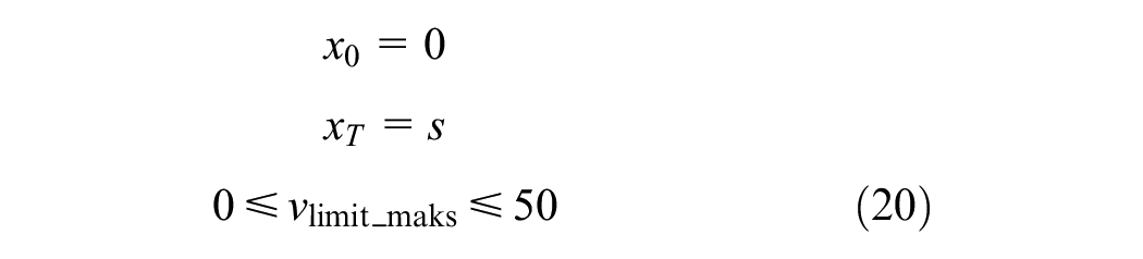
In this study, the target time is assumed to be constant between departure movements at two consecutive stations. During this period, the travel time of the train and the waiting time at the station may vary, within certain limits, in line with the approach of minimizing the amount of energy consumption and limiting the size of the on-board energy storage unit. The time data of the movement of the train between two stations are limited in accordance with Formulas 18 and 19.
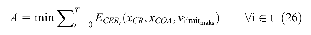
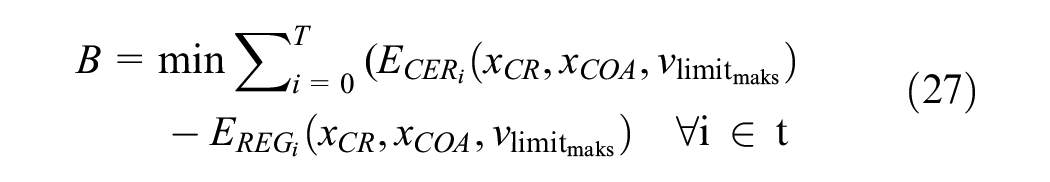
In the proposed optimization solution, three variables, namely the transition point of the train to the cruising mode, the transition point to the coasting mode and the maximum allowable operation speed, are considered. For these variables, GA has been used to solve the values that will minimize the energy consumption and keep the on-board energy storage unit size requirement at the optimal level, which contribute to the reduction of the total energy consumption by considering the recovery of braking energy. The objective function in the optimization problem applied in the GA is indicated by Function 28. Minimization of total energy consumption and optimal on-board energy storage unit sizing are provided by Formulas 26 and 27, respectively.

Genetic Algorithm (GA)
In addition to being a process that guides biological evolution, GA is a method used to solve optimization problems based on natural selection. GA, repeatedly modifying a population of individual solutions, uses randomly selected parents from the current population to produce children that try to preserve the best traits for the next generation. This is repeated at each step ( 4 ).
GAs start with a population of randomly generated sequence structures and this is called the “initial population.” The initial population is run by three main operators, namely mutation, crossover and selection, to obtain better populations. Each resulting population is evaluated. If the termination criteria are not met, the cycle continues. Each cycle, including operator operations and evaluation procedure, is known as a “generation” in GA terminology ( 28 , 29 ).
GA has a 5-stage process structure. The iterative stages are: determination of the initial population of N individuals, evaluation of the objective function for each individual, fitness-based selection of the best individuals, production of new individuals, and stopping of the iteration when the stopping criteria is satisfied ( 4 , 12 , 30 ). The flowchart of a basic GA process is shown in Figure 10.
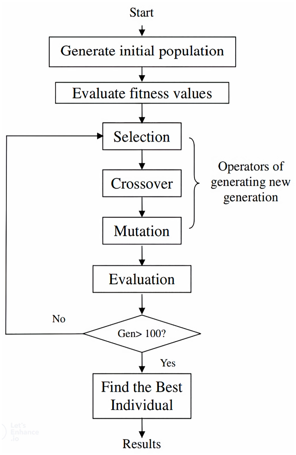
Genetic algorithm flowchart ( 29 ).
GA has been successfully applied in studies addressing the balance between energy consumption and travel time in rail systems. Generally, GA is used to determine coasting points in energy optimization studies. The objective function considered in the study consists of two parts. These sections are intended to optimize traction power consumption and braking energy recovery, provided that they remain within the travel time limits tolerated in the operation. In this direction, optimization was achieved through three variables: coasting point, cruising point, and maximum speed limit allowed in the operation.
It is preferred that GA requires only the objective function, is based on searching for the best solution according to the principle of survival of the fittest in complex spaces, and reaches the solution in a shorter time with an effective search by scanning a certain part of the solution space. It has been observed that GA is frequently used and successful in solving energy optimization problems in rail systems. For these reasons, GA was used to solve the optimization problem of energy consumption, which is a very complex NP problem, trying to determine the speed profile that includes the recovery of braking energy.
Description of the Problem
Ground-level traction power supply systems have advantages as well as disadvantages compared with other traction power supply systems. In the ground-level traction power supply system used in the tram line under consideration, it is not possible to return the energy generated during braking to the line ( 31 , 32 ). Therefore, it is not possible for the energy generated during the braking movement of a train to be used by another train, or returned to the electricity distribution network with reversible traction power substation and stored in a wayside energy storage unit on the line route. The only way to benefit from braking energy in the APS system is to use an on-board energy storage unit.
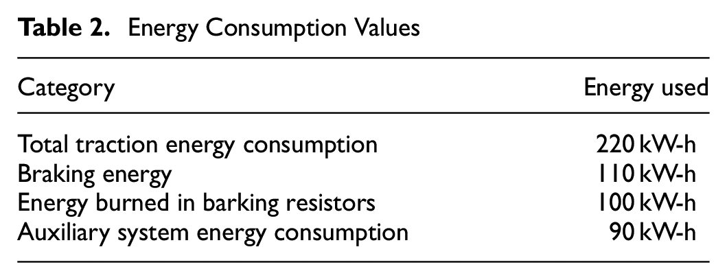
Energy consumption values were observed during the movement of a tram vehicle which does not have an energy storage unit with the power and energy density to store the braking energy that will emerge during braking, along the determined route in the line with ground-level traction power supply system. From the values obtained, it is seen that there is a braking energy recovery of approximately 45% of the total traction system energy consumption. It is not possible to transfer the braking energy recovered in the current system structure to another vehicle that is on the line or to store it in on-board energy storage units. Therefore, approximately 91% of it is burned in braking resistors and 9% is spent in auxiliary power systems. The energy consumption data of a train with an 6 passengers/m2 (AW3) load, which makes three full turns on the determined route, is given in Table 2.
Energy Consumption Values
The presence of signalized intersections, pedestrian crossings, switch zones, and frequent passenger stations along the route of tram lines causes many speed limits on the movement routes of tram vehicles, and, therefore, train movements in acceleration and deceleration mode are quite high. This situation significantly increases energy consumption and the amount of braking energy generated. In a system where there is no on-board energy storage unit that can store the braking energy, a serious negative effect will occur in energy efficiency as the amount of energy wasted in the braking resistors increases. If a suitable on-board energy storage unit is available, the excess braking action will increase the size requirement of the energy storage unit more than necessary. Considering all these situations, it is necessary to reduce the total energy consumption to the lowest possible level and determine the optimal recovery potential of braking energy.
The recovery potential of braking energy is handled with the principle of optimal energy storage unit sizing, which will minimize the effect of energy storage unit weight on vehicle weight and traction power consumption by minimizing the number of operations in braking mode during the train movement with the appropriate speed profile.
Energy Management Strategy
In this study, the movement of the train between stations, from its departure at one station to its stop at the next station, is handled separately for each inter-station area. On the tram line with a ground-level energy supply system, the use of an on-board energy storage unit in a hybrid structure, consisting of a battery unit that can be used as a backup energy source in limited conditions in emergency situations and a supercapacitor unit that can provide braking energy recovery, is assumed.
Travel time and energy consumption in rail system enterprises are directly affected by train driving modes such as motoring, cruising, coasting, and braking ( 33 ). Many speed profiles can be encountered in the literature and these speed profiles have their own driving mode sequence. There are speed restrictions at many points on the line route because of junctions with pedestrian and highway intersections and turnouts on the tram lines. For this reason, the most applicable energy-efficient speed profile that can provide the expected running time can be obtained with the sequence of motoring–cruising–coasting–braking. The reference speed profile applied in the study according to the operating mode is shown in Figure 11.
Reference speed profile strategy ( 7 ).
Because of the structural features of the ground-level traction power supply system, the recovery of braking energy can only be achieved with on-board energy storage units. In this study, two operating modes—operation and failure—were determined as an energy management strategy. There are four driving modes in the operation mode. In the motoring phase, the supercapacitor part of the hybrid on-board energy storage unit will support the ground-level traction power supply system. During the cruising and coasting movement phases, the energy storage unit will not be active and the vehicle will provide the energy from the ground-level traction power supply system. The braking energy generated during the braking phase will be stored in the supercapacitors as it is not possible to return it to the ground-level traction power supply system. In the operation mode, the battery pack is completely passive. In the failure mode, energy cannot be received from the ground-level traction power supply system. There are three driving modes, in the order of: motoring–cruising–braking. The failure mode has been determined to prevent road traffic disruption by saving the train from the junction area for a limited distance with a low speed limit if the energy supply from the ground-level traction power supply system is lost in the intersection areas of the tram line, which has intersections with the highway at many points on the line route. During the motoring phase, the battery unit, which is kept as a backup power source in the operation mode, will take on the role of the main power source. The supercapacitor part of the hybrid on-board energy storage unit will support the battery unit to reduce the impact on the life of the battery unit. Vehicle movement during the cruising phase will be provided by the battery unit. The braking energy generated during the braking phase can be stored by supercapacitors. The energy management strategy according to the transitions between train movement modes and operating modes is shown in Figure 12.
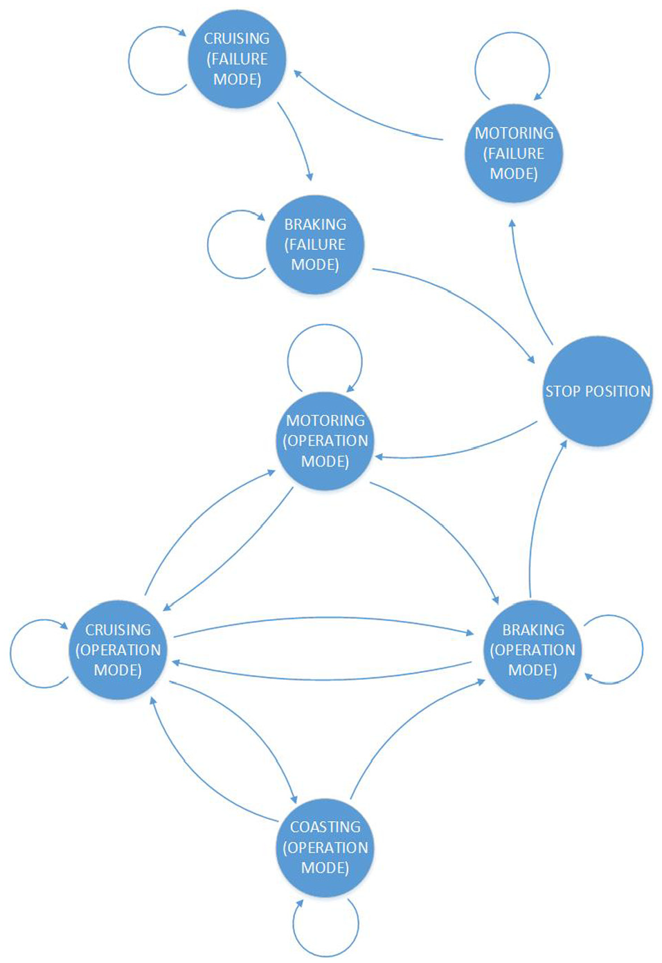
Energy management strategy.
Single Train Simulation
In this section, a sample single train simulation is presented to show the results of the model where we present the energy efficiency solution for the tram line with ground-level traction power supply system using the Istanbul T5 tram line operation datas. The Istanbul T5 tram line has a length of approximately 9 km from Cibali station to Alibeyköy Cep Otogar station.
The speed profile of the train between two consecutive stations has been optimized for a total of 11 regions, separately for each inter-station region. While determining the optimal speed profile, constraints of the running time of the train between the two stations and the waiting time at the station were also taken into account. The map indicating the layout of the T5 tram line is shown in Figure 13. The map shows the final design route of the tramline. In the study, the section between Cibali and Alibeyköy Cep Otogar, which is the first stage of the tram line to be put into operation, was discussed.
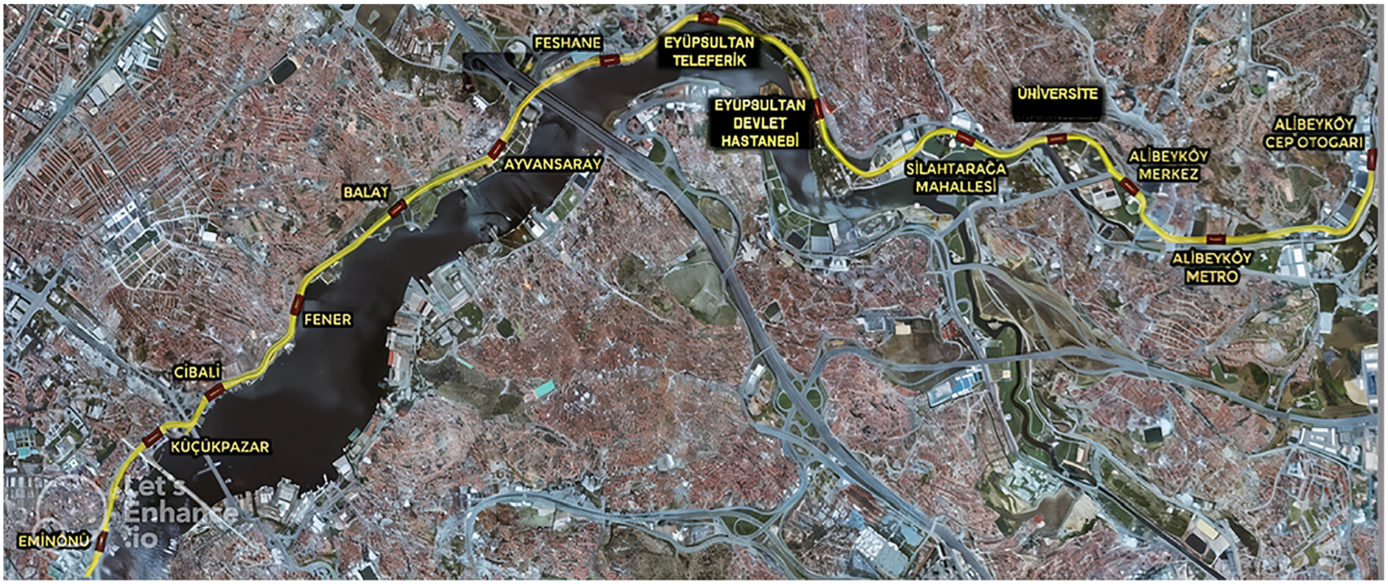
Layout of the T5 tramline.
The speed-position graph in Figure 14, the speed-time graph in Figure 15 and the traction power consumption-recovered brake energy graph in Figure 16 were obtained from the GA solution of the model created according to the objective function defined in Equations 26, 27 and 28 for the segment between Feshane and Teleferik stations. In the relevant segment, the traction power consumption is 2.3538 kW-h and the recovered braking energy is 0.5606 kW-h. The train reached the target point in 108.2 s, which is close to the targeted running time (110 s).
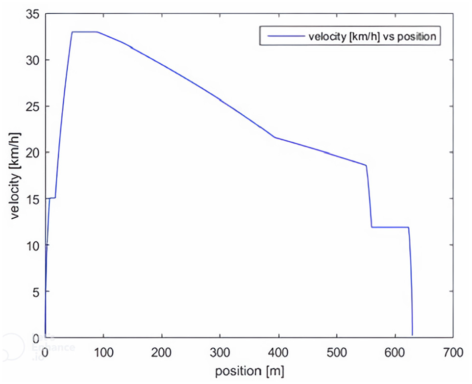
Velocity–position graph between Feshane and Teleferik stations.
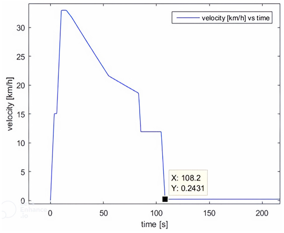
Velocity–time graph between Feshane and Teleferik stations.
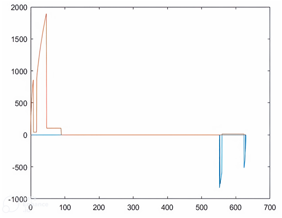
Traction power consumption and recovered braking energy–position graph between Feshane and Teleferik stations.
In this study, the regions between each station were analyzed separately. Therefore, it is not possible to specify a holistic velocity–position graph and other graphs. According to the optimizastion results, speed–position graphs are shown separately in Figure 17 and traction power consumption and recovered braking energy–position graphs are shown in Figure 18 for all inter-station regions.
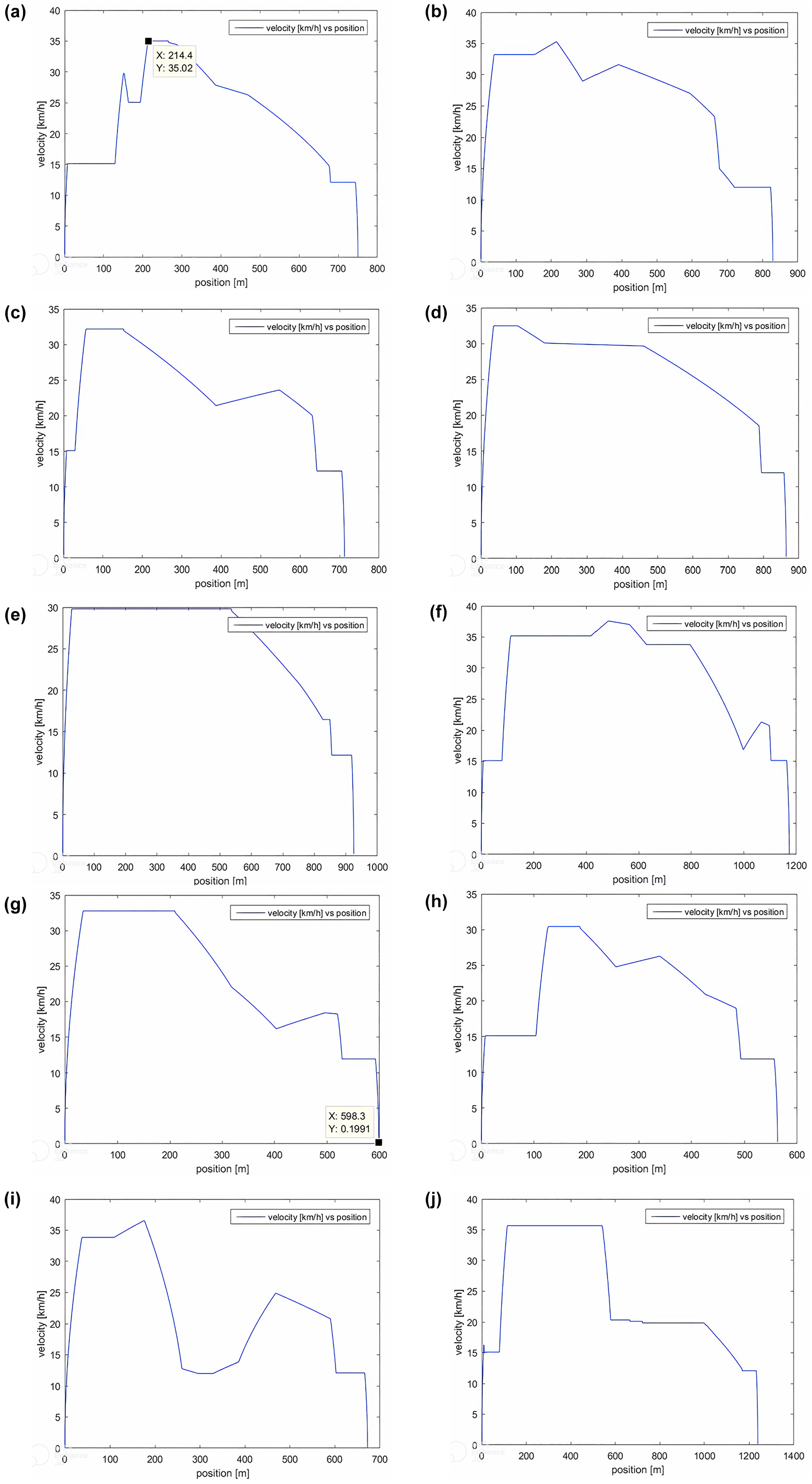
Velocity–position graphs: (a) Cibali–Fener, (b) Fener–Balat, (c) Balat–Ayvansaray, (d) Ayvansaray–Feshane, (e) Eyüpsultan Teleferik–Eyüpsultan Devlet Hastanesi, (f) Eyüpsultan Devlet Hastanesi–Silahtarağa Mahallesi, (g) Silahtarağa Mahallesi–Üniversite, (h) Üniversite–Alibeyköy Merkez, (i) Alibeyköy Merkez–Alibeyköy Metro, and (j) Alibeyköy Metro–Alibeyköy Cep Otogarı.
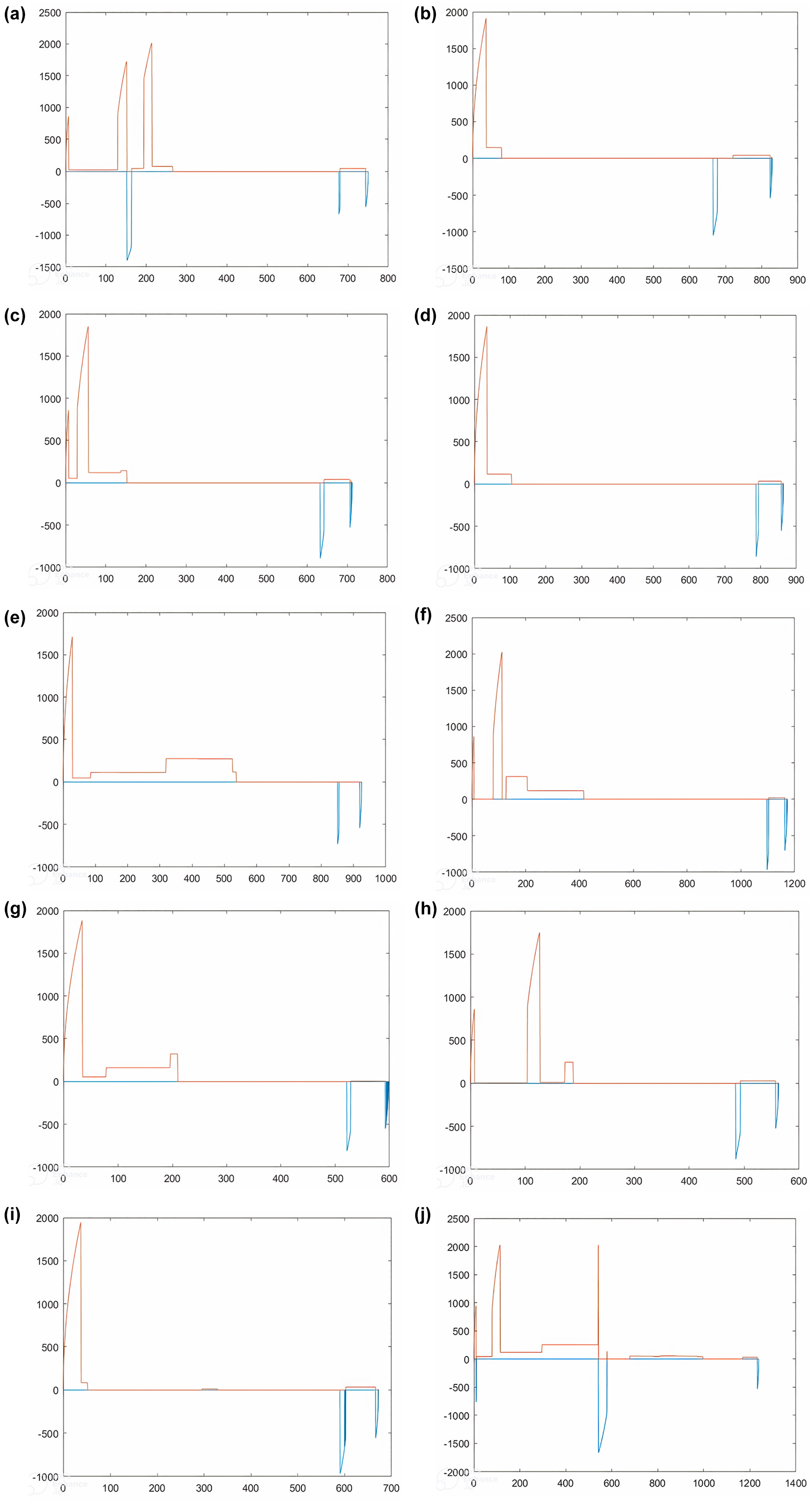
Traction power consumption and recovered braking energy–position graphs: (a) Cibali–Fener, (b) Fener–Balat, (c) Balat–Ayvansaray, (d) Ayvansaray–Feshane, (e) Eyüpsultan Teleferik–Eyüpsultan Devlet Hastanesi, (f) Eyüpsultan Devlet Hastanesi–Silahtarağa Mahallesi, (g) Silahtarağa Mahallesi–Üniversite, (h) Üniversite–Alibeyköy Merkez, (i) Alibeyköy Merkez–Alibeyköy Metro, and (j) Alibeyköy Metro–Alibeyköy Cep Otogarı.
As seen in Figure 15, in consequence of the solution of the cruising mode transition point, the coasting mode transition point and the maximum allowable operation speed values for the segment between Feshane and Teleferik stations by means of GA, it is seen that the peak consumption values at the beginning region and the recovery of braking energy in the stop region occur. A low level of energy consumption was observed with the cruising and coasting modes at the intermediate region of the motion. By limiting the transition points to braking, the braking energy used to determine the on-board energy storage unit sizing potential is minimized. In this context, the effect of on-board energy storage units on vehicle weight has been minimized.
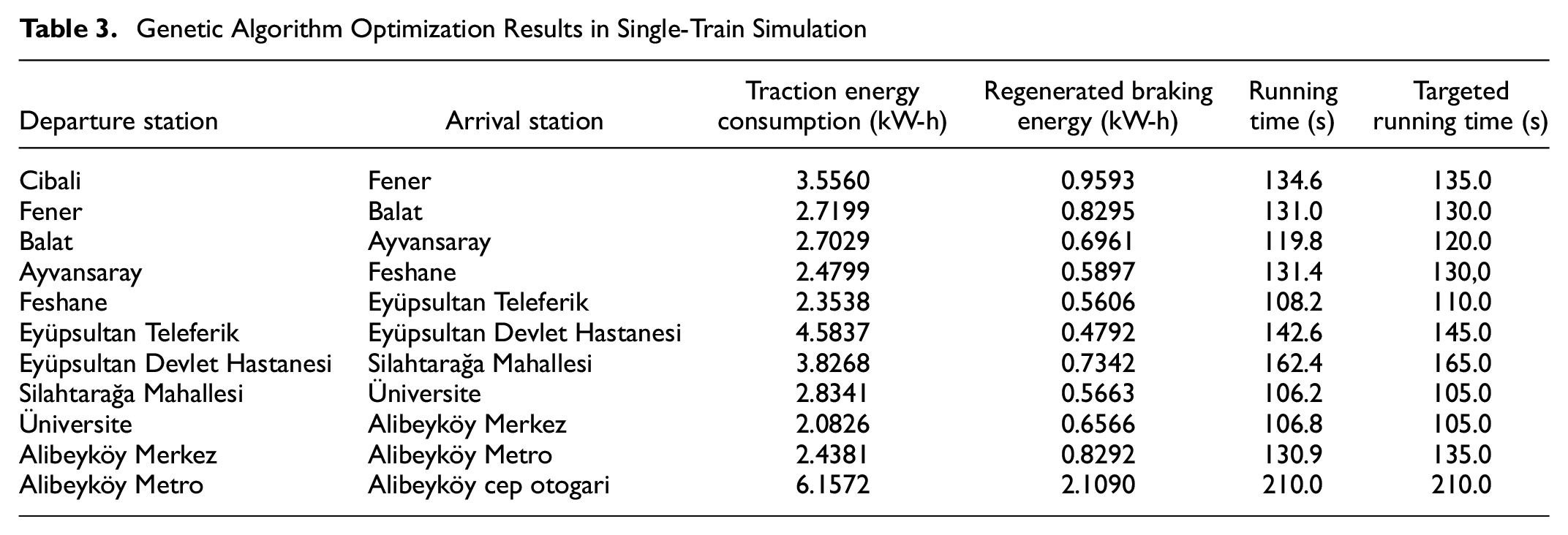
The values obtained for 10 regions in the optimization solution applied using GA in accordance with the proposed energy management strategy are given in Table 3.
Genetic Algorithm Optimization Results in Single-Train Simulation
Conclusion
In this article, a tram line with ground-level traction power supply system and a battery system that will enable the train to supply traction power under limited conditions in case of power cuts are discussed. The mentioned tram line was analyzed based on the Istanbul T5 tram line operation data. As an addition, a hybrid energy storage system with integrated battery and supercapacitor units has been proposed for the tram line with a ground-level traction power supply system, and energy efficiency is aimed for in accordance with the recovery of braking energy.
In this study, a train speed profile optimization model was developed in accordance with the transition points between the movement modes and the maximum allowable operation speed within the running time limits. To increase energy efficiency, the determination of the transition points suitable for cruising and coasting motion modes and the maximum allowable operating speed are provided by GA. With the speed profile obtained, total energy consumption and braking energy recovery potential, which will give an idea about on-board energy storage unit sizing, are limited by reducing the peak consumption points to the station starting points and the braking points to the station stopping points. The developed model can increase energy efficiency in tram lines that have many pedestrian and highway intersection points and variable speed limitation at many points along the line route.
This study is an example based on Istanbul T5 tram line operation data, and limitations based on operation and vehicle data, such as maximum and minimum running times, speed limitations, and maximum acceleration and deceleration, have been taken into account for each inter-station zone. In the simulation model created in the MATLAB environment, approximately 95% accuracy in energy consumption and 98% accuracy in running time was obtained according to real data. In the optimization study using GA, it was observed that the preferred running times were achieved at an average of 99.6%. The traction power energy consumption between Cibali and Alibeyköy Cep Otogarı has been reduced from approximately 69 kW-h to 36 kW-h with the optimized speed profile according to the existing system structure, operation structure and train drivers’ behavior. The braking energy recovery potential was found to be 9 kW-h in the recommended speed profile. Approximately 1 kW-h of the recovered braking energy will be used in auxiliary systems. In the case of using the proposed hybrid energy storage unit, the braking energy can be stored in supercapacitor units and the total energy consumption can be reduced to approximately 28 kW-h. In accordance with these results, the gain in total energy consumption is expected to be approximately 60%.
The study does not include any scenarios that would cause the planned normal running graphic of the train to be disrupted because of environmental factors, other than speed limits and station stopping points. In subsequent studies, more realistic results can be obtained by considering scenarios in which the operation will be negatively affected.
Footnotes
Author Contributions
The authors confirm contribution to the paper as follows: study conception and design: A. Koyun, R. Yumurtaci; data collection: A. Koyun; analysis and interpretation of results: A. Koyun, R. Yumurtaci; draft manuscript preparation: A. Koyun, R. Yumurtaci. All authors reviewed the results and approved the final version of the manuscript.
Declaration of Conflicting Interests
The author(s) declared no potential conflicts of interest with respect to the research, authorship, and/or publication of this article.
Funding
The author(s) received no financial support for the research, authorship, and/or publication of this article.
Data Accessibility Statement
The data that support the findings of this study are available from Metro Istanbul Inc. but restrictions apply to the availability of these data, which were used under license for the current study, and so are not publicly available. Data are, however, available from the authors on reasonable request and with the permission of Metro Istanbul Inc.