
Abstract
Alternative fuel vehicles may pose challenges to evacuation planning because of their short driving range and the sparse refueling infrastructure existing on transportation networks. Deployment and strategic siting of emergency refueling stations are needed to support the evacuation of alternative fuel vehicles to reach a shelter. This study proposes a location-routing problem with hop constraints that optimize the placement of emergency refueling stations of each alternative fuel type to support evacuation routing. We develop a Benders-inspired decomposition method with a transformed network to solve the location problem and a matheuristic branch-and-price method to design evacuation routes that minimize travel and refueling time and satisfy the hop constraints of each vehicle type. Our numerical experiments, focusing on the South Florida network, uncover the impacts of alternative fuel vehicle specifications and vehicle heterogeneity on the deployment plan.
Keywords
Despite their sustainability and economic benefits, growth in the market for alternative fuel vehicles is subject to barriers of infrastructure availability ( 1 – 3 ). Compared with gasoline vehicles, alternative fuel vehicles have limited driving ranges, depending on their fuel tank or battery pack sizes, sparse refueling and charging infrastructure networks, and long refueling and charging times. The driving range of an electric vehicle (EV) varies from 58 to 405 miles (median: 234 miles) on a single full battery charge. These driving ranges are shorter than those of gasoline vehicles, whose median range is 418 miles ( 4 ). In addition, the refueling networks for these emerging vehicle technologies remain sparse, including only 48 hydrogen, 832 natural gas, and 49,441 EV charging stations ( 5 ), compared with more than 146,000 registered gasoline stations, in the USA as of 2022 ( 6 ). Like gasoline vehicles, hydrogen fuel cell and natural gas vehicles can refuel in less than 4 min for a 20-gallon-equivalent tank size ( 7 , 8 ). However, charging is time-consuming for battery EVs whose charging rate varies from 5 miles/hour to 240 miles/hour, depending on the charging efficiency and power level ( 9 ).
Vehicle and refueling infrastructure constraints are expected to add new challenges during natural and anthropogenic hazardous events that warrant preemptive evacuations ( 10 , 11 ). The evacuation distance to safety often exceeds the driving range of a single full battery capacity for EVs and may require frequent charging stops. Studies of Hurricanes Katrina and Rita show that the evacuation distance exceeded 388 miles ( 12 , 13 ). With the advent of alternative fuel vehicles and their particular refueling infrastructure dependencies, evacuees traveling in alternative fuel vehicles are susceptible to being stranded during emergencies without sufficient state-of-charge or fuel to reach designated shelters or safe zones ( 14 ).
Strategically placing alternative refueling stations can help reduce the vulnerability of alternative fuel vehicle owners and improve their evacuation clearance times before imminent disasters ( 10 , 15 ). The U.S. Federal Emergency Management Agency ( 14 ) and Federal Highway Administration ( 16 ) suggest evacuating vehicles through respite sites with gasoline stations; however, there is no provision for refueling alternative fuel vehicles. Responding to recent ambitious federal and state programs for accelerating alternative fuel vehicle adoption ( 17 , 18 ), it is essential to consider the deployment of alternative refueling stations to support evacuation planning.
This study aims to develop an optimal placement plan for emergency alternative refueling stations to support a diverse set of vehicle fuel types and their evacuation demand on designated evacuation routes. The emergency refueling stations may be financed and owned by public agencies, in contrast with the current refueling infrastructure network which is owned and operated by industry. The current deployment of alternative refueling stations focuses on enabling habitual travel demand and meeting profit maximization objectives ( 19 – 21 ), not evacuation demands and resilience objectives. The emergency refueling station placement would support the existing refueling stations in covering the evacuation demand. We develop the alternative refueling station location model, based on a location-routing problem, for optimal deployment of emergency refueling stations. We use a Benders-inspired decomposition procedure to solve the location problem and a matheuristic branch-and-price method to design evacuation routes. We apply the proposed framework to the South Florida transportation network: (i) to plan the siting of emergency refueling stations and (ii) to evaluate the role of alternative fuel vehicle specifications and vehicle heterogeneity in the deployment plan. This is the first paper to meet this timely research objective by proposing a new mathematical formulation that describes this problem and its algorithmic solution.
Literature Review
In this study, the facility location problem models the deployment of emergency alternative refueling stations as part of the evacuation logistics of alternative fuel vehicles. Facility location problems are integer programming problems and are commonly applied for the strategic placement of stationary infrastructure. Facility location models for alternative refueling station siting focus on integrating the side constraints associated with the refueling process through functions that describe the relationships between the limited driving range, sparse fuel or power supply, and the long refueling/charging time, for business-as-usual purposes. The flow refueling location model for alternative fuel vehicles and its extensions capture the deviating or detoured flow from refueling requirements ( 22 , 23 ). Network equilibrium models capture the interactions among public charging opportunities, prices of electricity, and route choices of EV drivers ( 21 , 24 ). Bi-level facility location models leverage the network equilibrium for routing choices and capture waiting times associated with EV charging under the assumption of infinite queues ( 25 ), while mixed-integer EV charging infrastructure location problems minimize the investment cost, EV drivers’ delay caused by the detours for recharging, and queue and waiting times during charging ( 20 ).
Evacuation road network operations are subject to non-habitual travel behaviors and additional uncertainties (e.g., unusual route choices, road and facility capacity, and dynamic demand) ( 26 ), as well as complex hierarchical coordination (e.g., from damage to communication lines, involvement of multiple agents like government and industry in emergency response, unavailability of accurate real-time demand information) and limited resources (e.g., supply, people, transportation links’ capacity, fuel constraints) ( 27 ). Such challenges need to be considered in the planning process for refueling facilities that support evacuation. Past evacuation studies on refueling station dependency focused on the deployment and supply planning of refueling stations for gasoline vehicles. Simulation-optimization frameworks were used for optimal deployment of gas stations and their supply for hurricane evacuation ( 28 ) and the so-called “idealized model” manages optimal gasoline supplies and evacuation routing with fuel capacity constraints for hurricane evacuation ( 29 ). Few studies investigated the effect of alternative refueling station location on preemptive evacuation performance. Adderly et al. ( 10 ) provide a comprehensive review of EVs and their policy implications in emergency management. Feng et al. ( 11 ) examine the feasibility of EVs to evacuate during hurricanes using a Florida case study. Both works indicate that the deployment of emergency refueling stations may be needed as the alternative refueling networks remain sparse. MacDonald et al. ( 30 ) develop a queueing model to optimize the electricity supply of existing alternative fuel vehicle charging stations for evacuation demand. Li et al. ( 31 ) design a three-stage framework to design an optimal EV mass evacuation plan with existing charging facilities. Purba et al. ( 15 ) develop novel evacuation route planning considering the existing refueling stations of alternative fuel vehicles in the network, and highlight the importance of refueling station location in supporting evacuation operations. No other work has modeled the optimal deployment of emergency refueling stations to support evacuation planning in addition to existing refueling stations; our paper aims to bridge this knowledge gap.
Problem Formulation
We present the refueling station location model to support preemptive evacuation routing plans for multiple alternative fuel vehicle types. The formulation is structured as a location-routing problem that optimally deploys emergency alternative refueling stations according to demand from alternative fuel vehicles during evacuation. Purba et al. (
15
) propose the
Our model assumes that every alternative refueling station has enough fuel and parking capacity to serve all necessary vehicles without congestion or queues forming. The assumption is aligned with a preemptive evacuation order, in which case emergency planners are well informed about the evacuation demand. Emergency planners can guarantee that the deployed and operated refueling stations must fulfill the refueling needs of all necessary vehicles during a preemptive evacuation. We further assume that evacuees start with a fully fueled vehicle or with a full state-of-charge and that they are well informed about the mandated evacuation route designation.
In the remainder of this section, we define the notation, provide a formal problem statement, and present the mathematical formulation of the problem.
Definitions and Notations
Let
The set of evacuee origin nodes heading to shelter
We define
Any node that belongs to
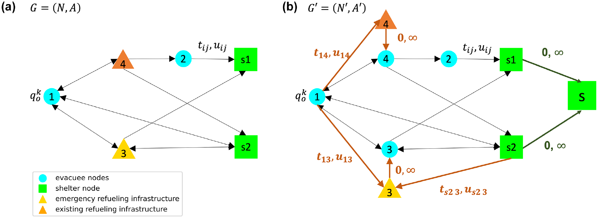
(a) Network topology with an existing refueling station, a candidate emergency refueling station, and multiple shelter nodes, and (b) modified network topology with a super shelter node and dummy refueling nodes.
In our model, each evacuee originating from
The driving range constraint for each vehicle of fuel type
Figure 2 presents an example network to illustrate the usable evacuation paths with hop betweenness constraints. Consider a network topology with one refueling station located at node
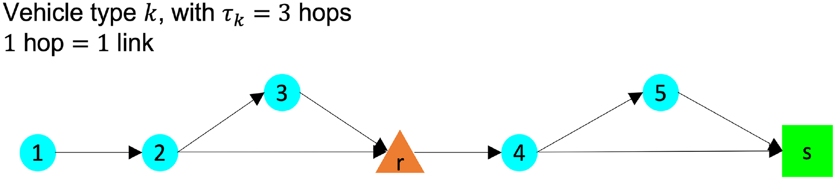
Example of network topology with five evacuee nodes, an existing refueling station, and a shelter node.
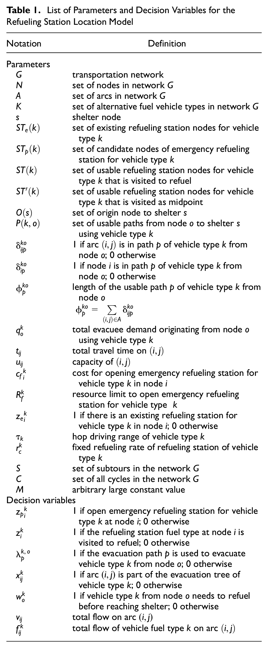
There are seven sets of decision variables in this model. The first two are associated with the deployment of emergency refueling stations. We define binary variables
List of Parameters and Decision Variables for the Refueling Station Location Model
Mathematical Formulation
We provide the formulation of the problem in Equations 1 through 20.
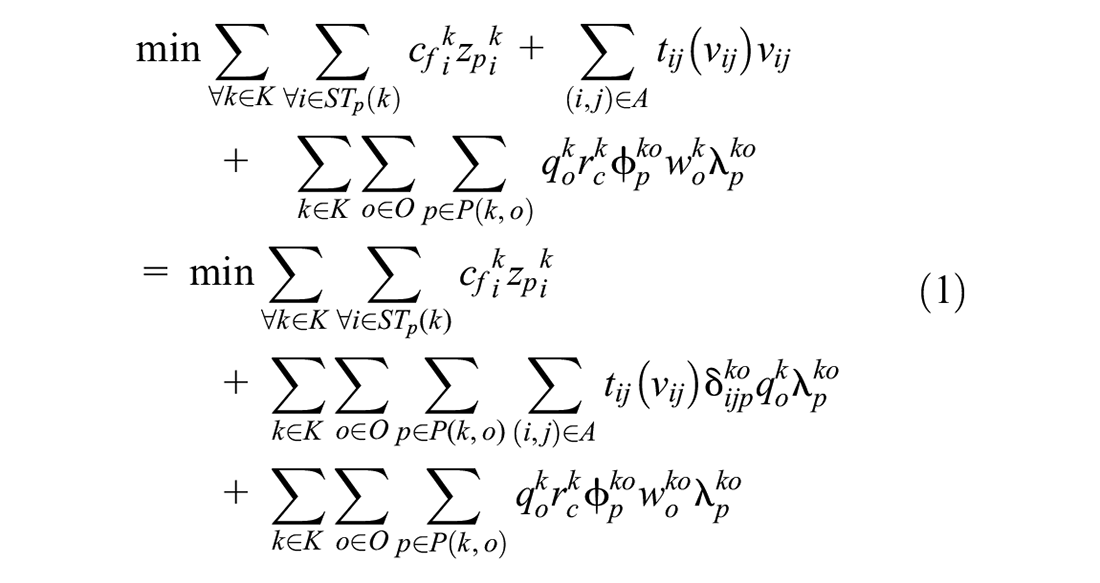


The objective function (Equation 1) aims to minimize the total cost of opening emergency refueling stations and the total system evacuation time by summing the time spent traversing each link on the evacuation network and the refueling time. Constraints in Equations 2 and 3 identify that a node could host the usable refueling station if either an existing or emergency refueling station is deployed. The next constraints (Equation 4) limit the total emergency refueling stations that can be opened for each fuel type.
The constraints in Equations 5 through 9 are traffic assignment constraints. Constraints 5 and 6 keep track of the total flow of each vehicle type
Solution Methods
This section presents a decomposition method inspired by Benders decomposition for solving the refueling station location model. The refueling station location model is formulated as a mixed-integer nonlinear problem, which is compositionally intractable as the size of the network increases. Specifically, our model is structured as a path-based location-routing problem. Benders decomposition has been used to provide both exact and heuristic solutions to the location-routing problem ( 33 – 36 ) and multi-stage problem (relevant to our problem) ( 37 – 40 ) with side constraints.
In our formulation,
Benders-Inspired Decomposition
The problem is decomposed into two problems: (i) location main problem (MP) to deploy optimally the emergency refueling stations for each alternative fuel type
Location MP
We define


The objective function (Equation 21) represents the decomposition reformulation for our objective function (Equation 1). Constraints in Equation 22 bound the optimal objective function for each generated cut. We define the cuts formulation in the following section. The constraint in Equation 23 defines the decision variable. The MP structure is a mixed-integer problem, solved using a commercial solver, such as Gurobi ( 43 ).
Routing SP
For every iteration
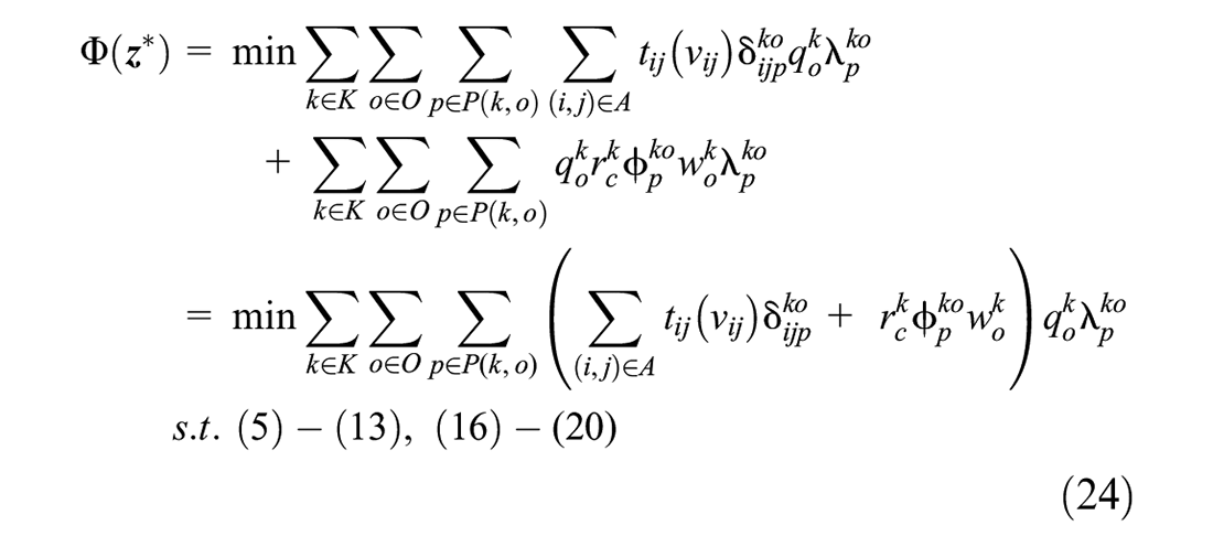
The objective function (Equation 24) minimizes the evacuation time of the total system by summing the time spent traversing each link on the evacuation network and the time spent refueling. This SP is formulated similarly as the
Cuts
We derive the cuts formulation for constraints (Equation 22) using the duality of the SP. In the SP,

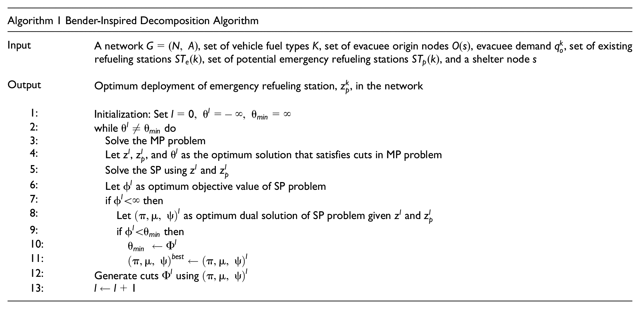
Finally, we solve the Benders-inspired decomposition as shown in Algorithm 1.
Branch-and-Price with Column Generation Matheuristic
We adopt the branch-and-price with column generation (
15
) to solve the SP as a
In this section, we define the restricted routing SP and the pricing SP for the
Restricted Routing SP
We define


Relaxing the integrality of
Pricing Routing SP
This section describes the pricing SP of the matheuristic column generation algorithm. We only consider the set of usable evacuation paths
Let
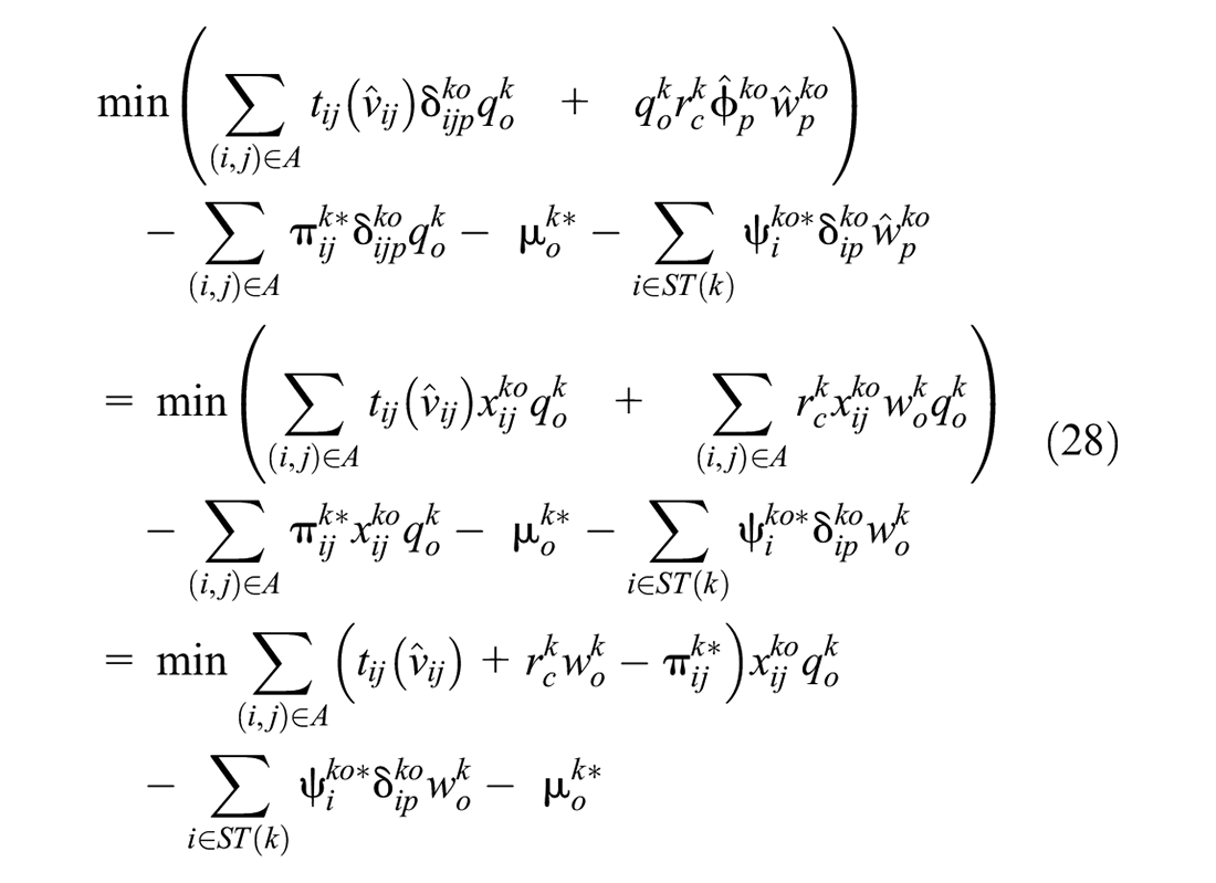


The objective function (Equation 28) tracks the reduced cost (pricing) for a new improving column, that is, the feasible evacuation path for each evacuee’s demand node and vehicle fuel type. Constraints in Equations 29–31 generate paths originating from an evacuee’s origin node to the shelter. Constraints in Equation 32 enforce the hop betweenness constraints. The constraints guarantee that for every subpath of the evacuation path that is at least
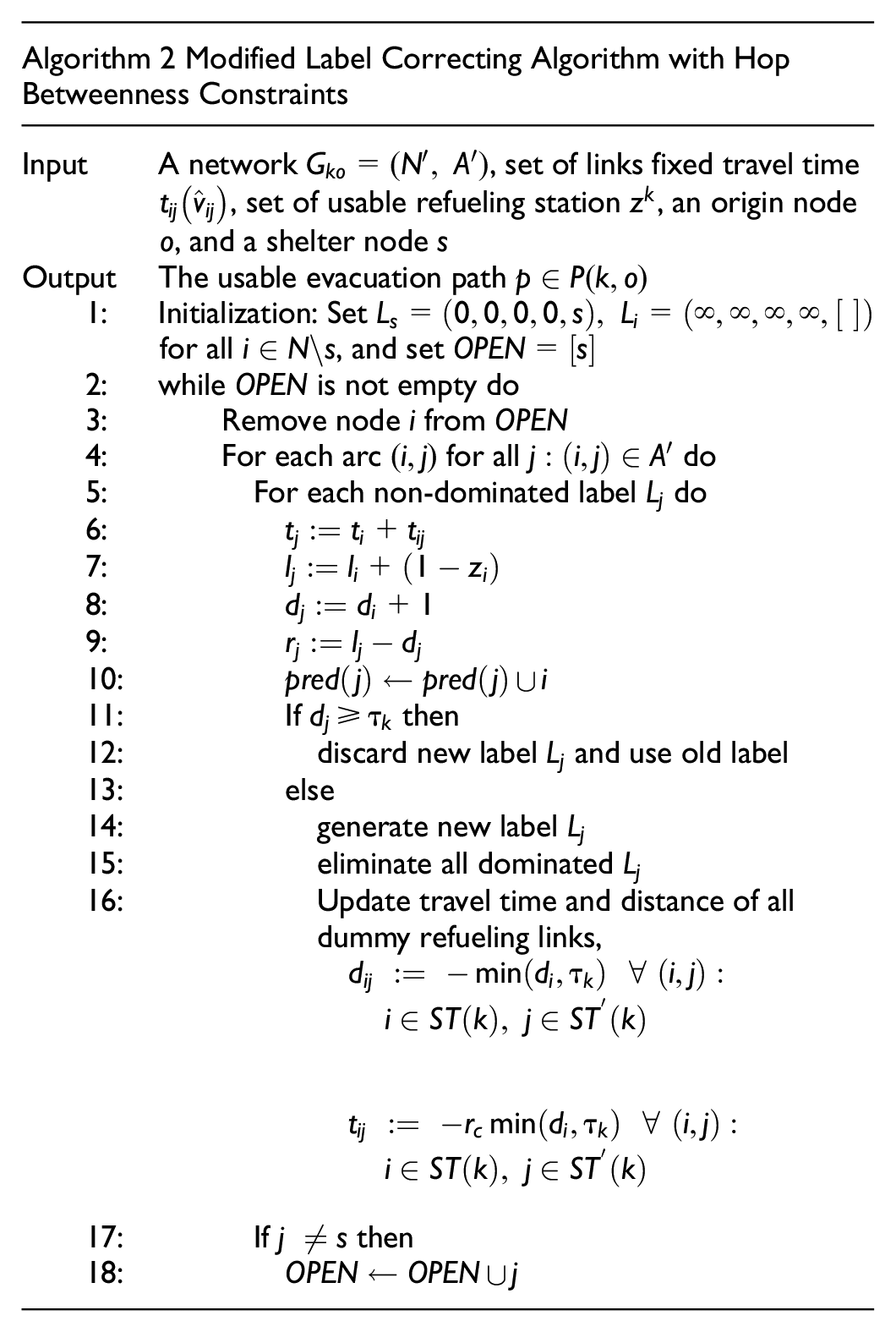
The pricing subproblem is computationally challenging to solve because of constraints (Equation 32) that could grow exponentially as we explore every subpath of all usable evacuation routes. We therefore develop the “modified label correcting algorithm with hop betweenness constraints” to generate the usable path and solve the pricing routing SP.
Modified Label Correcting Algorithm With Hop Betweenness Constraints
We present the modified label correcting with side constraints to solve the pricing routing SP. We are inspired by the well-known modified label correcting algorithm to find the shortest path (
44
). In each iteration, the modified label correcting algorithm visits each adjacent node to find the best route and keeps track of the distance along the route. In this study, the hop betweenness constraints are examined in each iteration of the label correcting algorithm: a vehicle of fuel type
In the remainder of this section, we define the notations, label feasibility and dominance, and the algorithm procedure.
Definitions and Notation
We introduce the new network topology setup to apply the modified label correcting algorithm with hop betweenness constraints, on top of those defined above. Let
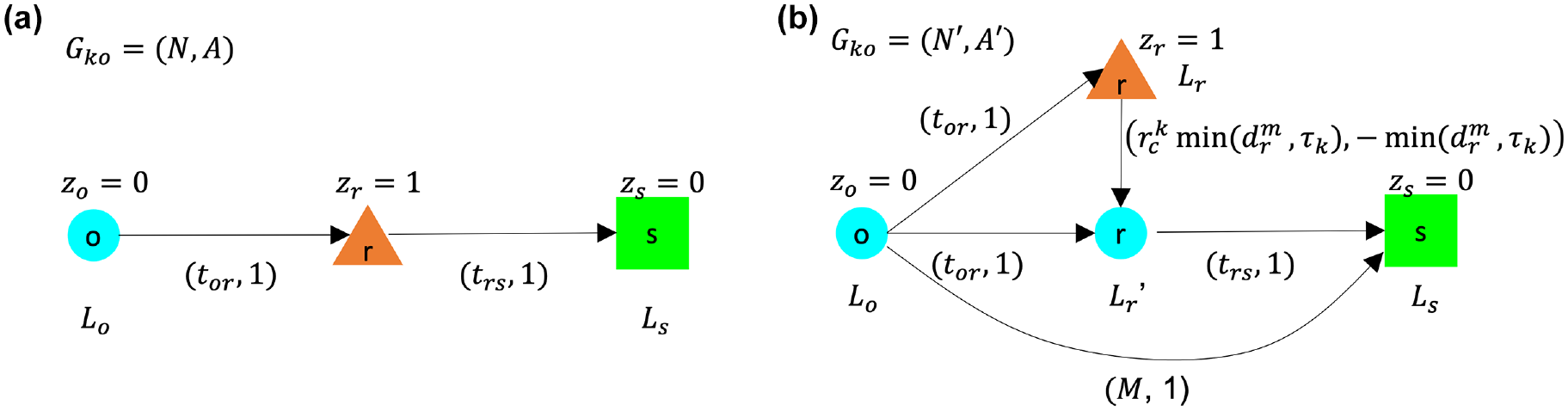
(a) Network topology
Furthermore, we define

where
Label Feasibility
The feasibility condition meets the hop betweenness constraints (Equation 32): for every subpath of the evacuation path that is at least
Label Dominance
The dominance condition informs the optimal usable evacuation path for a vehicle of fuel type
For
For
Let
Finally, we solve the modified label correcting algorithm with hop betweenness constraints following Algorithm 2. For step 3 the node sequence could follow first in, first out (FIFO), last in, first out (LIFO), or best-first search. We use the solution from this algorithm to calculate the pricing objective value (Equation 36).
Numerical Experiments
Experiments illustrate the application of the proposed refueling infrastructure model on the South Florida transportation network. Our analysis uses the South Florida transportation network to show the impact of driving range, the cost of refueling infrastructure, and the heterogeneity of vehicles in the deployment of emergency refueling stations to support alternative fuel vehicle evacuation plans. The optimization problems (MP and restricted routing SP) and solution algorithms are modeled and solved using the commercial solver Gurobi ( 43 ) and its Python interface. The networks and their operations are modeled using NetworkX ( 45 ).
Network Description
The network topology and properties of the South Florida transportation network are obtained from Sun et al. ( 46 ). The South Florida network consists of 82 nodes and 234 links. The total network travel demand is 65,707 vehicles with 83 origin–destination pairs. The total evacuee demand of each evacuee node is the total flow originating from the origin nodes of the habitual origin–destination matrix of the South Florida network ( 15 ). There are 31 nodes with zero evacuee travel demand, called “intersection nodes.” There are 32 nodes that may host alternative refueling stations in the South Florida network, where 30 nodes are obtained from the findings on optimal deployment by Sun et al. ( 46 ), and additional nodes 32 and 34 to cover evacuation demand on the northwest side of the network. We use these nodes to define the set of existing refueling stations and candidate nodes of emergency refueling stations.
We consider five shelters, located at nodes 1, 50, 64, 41, and 81. We added node s as a dummy shelter node and five direct links to node
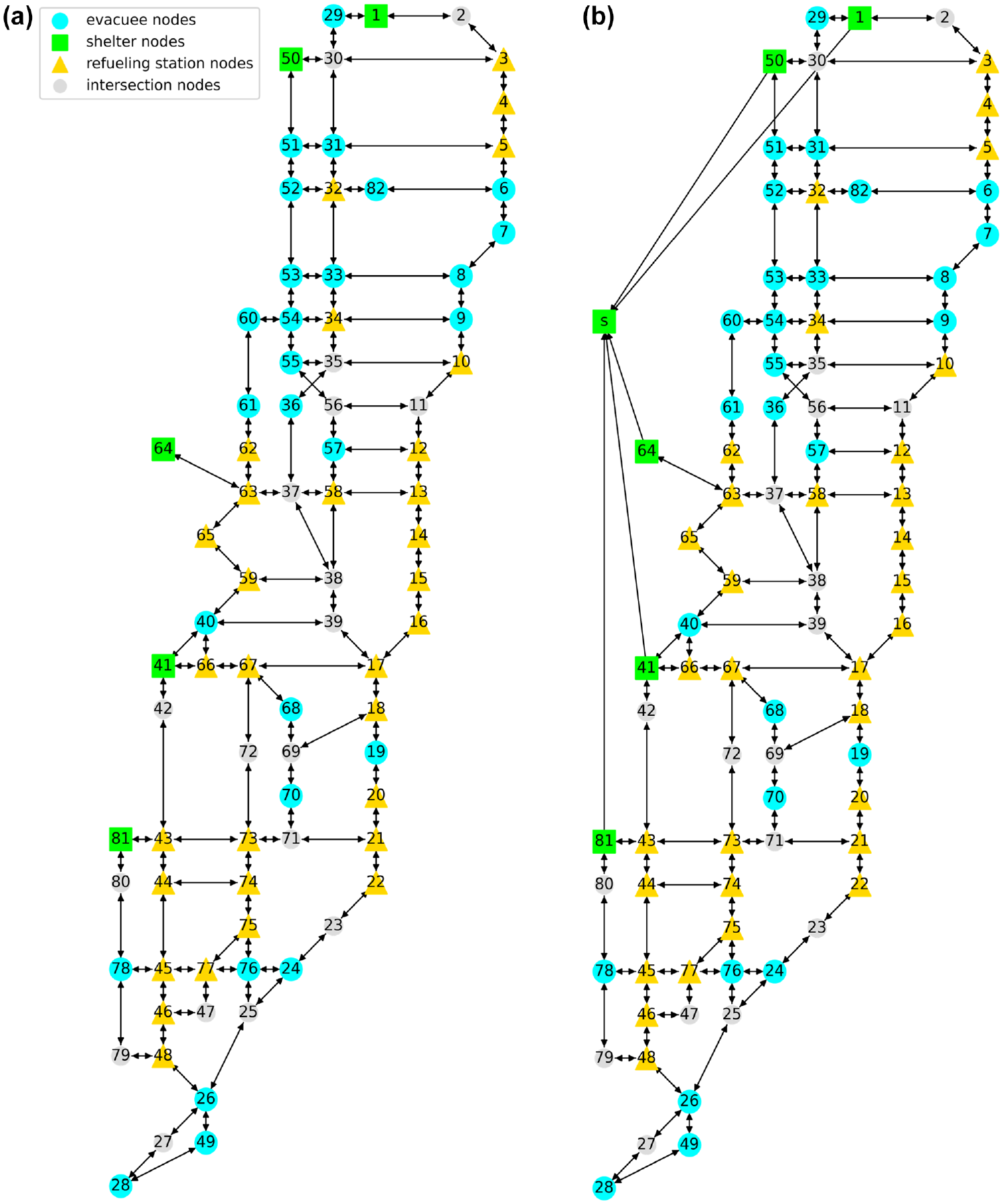
(a) The South Florida transportation network with 32 candidates of refueling station nodes and five shelter nodes, (b) the modified South Florida transportation network with a shelter node s.
Impact of Driving Range Constraints on the Deployment of Emergency Refueling Stations
We examine the impact of the driving range of alternative fuel vehicles in the deployment of emergency refueling stations in the evacuation network. In this experiment, we solve the problem where every evacuee uses a vehicle of the same fuel type to highlight the impact of refueling demand without considering the impact of vehicles of multiple fuel types on evacuation routing. We set
Figure 5 presents four optimal deployments of the emergency stations with their corresponding evacuation routes. The emergency refueling stations are deployed to accommodate the longest evacuation path in the evacuation routes and provide access to refueling stations within at most a span of driving range. For instance, in Figure 5a, the emergency refueling station is deployed at node 43, maintaining a span of four hops to accommodate evacuees along paths 28-49-26-48-46-45-44-43-81-s and 22-21-71-73-43-81-s. Similarly, in Figure 5b, we deploy four emergency refueling stations at nodes 32, 63, 17, and 43, resulting in refueling station access with a span of five hops in the network. As we increase the driving range, the emergency refueling stations are located with reduced density, resulting in reduced number of deployed emergency refueling stations.
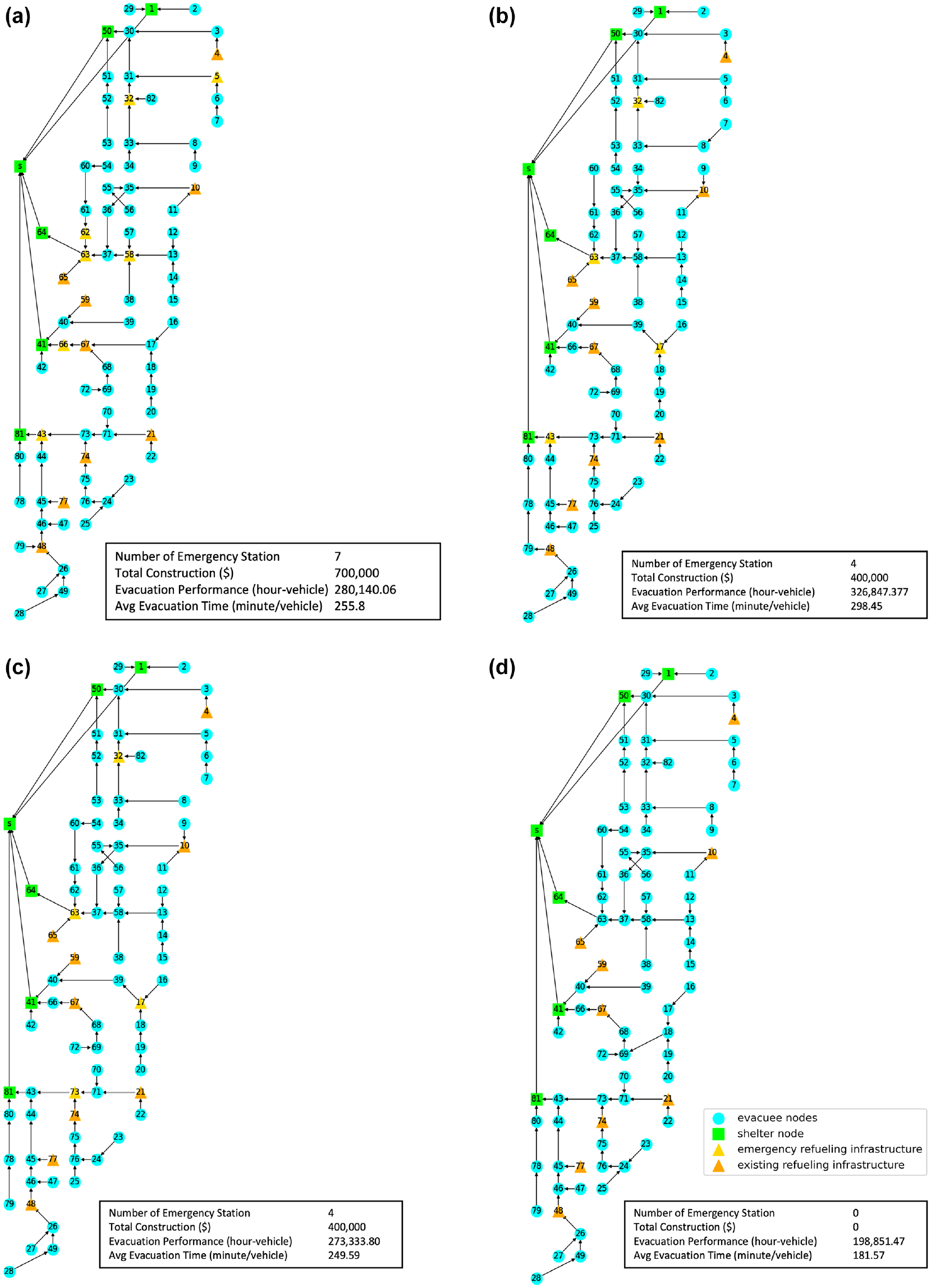
Optimal deployment of emergency refueling stations and evacuation tree routes for four cases of vehicle driving range: (a)
As shown in Figure 5a, the deployment of seven emergency refueling stations results in lower evacuation time than in Figure 5b with four emergency refueling stations deployed. Note that the objective function of the location model weighs the deployment cost and total system evacuation time equally. The optimal deployment and routing therefore depend on the trade-off between these objective components. As we increase the driving range, the overall objective value decreases, as shown in Table 2.
Optimal Deployment of Emergency Refueling Stations and Evacuation Performance for Different Driving Ranges
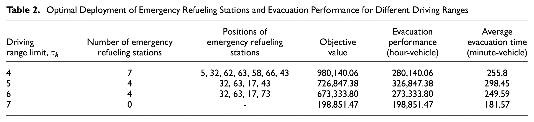
For the case of six hops, as shown in Figure 5c, we deploy four emergency refueling stations at nodes 32, 63, 17, and 73, resulting in lower evacuation time compared with the case of Figure 5b, as expected. In Figure 5c, the emergency refueling stations are deployed with a span of fewer than six hops. The optimal deployment also depends on the given potential location of emergency refueling stations. For instance, according to the refueling rule, the evacuation path 20-19-18-17-39-40-41-s must provide refueling access along its route. Through the given potential emergency refueling station set, we could only deploy on node 17, resulting in a span of fewer than six hops.
Figure 5d shows that no additional emergency refueling station is needed; the existing refueling network is sufficient to provide access to the evacuees following the designated routes. The evacuation route is unique and depends on the deployment of refueling stations and the vehicles’ driving range. It can be the case that for a particular driving range, the existing deployment of refueling stations is sufficient to support evacuation planning, and no emergency refueling stations are needed. Emergency planners should account for the vehicles’ driving range to site emergency refueling stations strategically, considering the accessibility of the network farthest from the shelter to meet evacuee demand.
Furthermore, in Figure 5a, we observe that the emergency refueling station at node 66 is located near the existing refueling station at node 67. Evacuees from nodes 72, 69, and 66 refuel at emergency station node 66, while all evacuees originating from nodes 16, 17, 18, 19, and 20 refuel at an existing station in node 67. Similarly, emergency stations are adjacently deployed at nodes 63 and 62. Evacuees originating from nodes 54, 60, and 61 refuel at the emergency station node 62 instead of node 63. We observe some adjacent deployments in Figure 5c. In our model, we follow the
Impact of Vehicle Heterogeneity on the Deployment of Emergency Refueling Stations
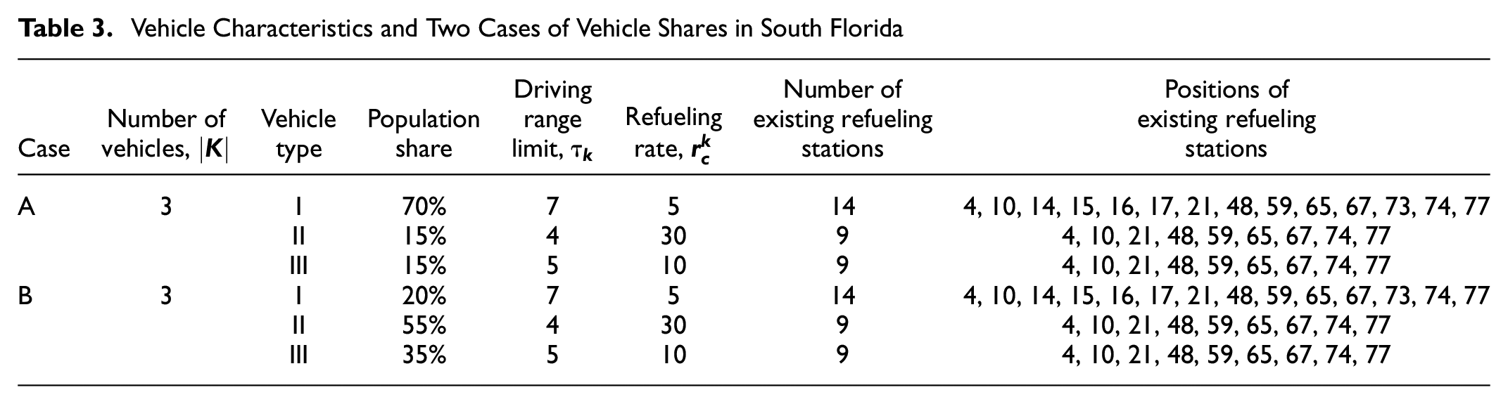
We assume three types of alternative fuel vehicles: vehicle type I represents a gasoline vehicle with a large driving range and a dense existing refueling station network; vehicle type II represents an alternative fuel vehicle with a short driving range and a sparse existing refueling station network; and vehicle type III represents an alternative vehicle fuel type with a medium driving range and a sparse existing refueling network. The vehicle characteristics and refueling station deployment for each type are presented in Table 3. We examine two cases of evacuation route design: in Case A, there are three vehicle types with type I dominating and in Case B, there are three vehicle types with type II dominating the share of alternative fuel technologies.
Vehicle Characteristics and Two Cases of Vehicle Shares in South Florida
We have already shown the optimal deployment for vehicles of type II only in Figure 5a, and for vehicles of type III in Figure 5b. In Case A, we consider three vehicle types: type I dominates the vehicle market, while types II and III are driven by smaller shares of drivers. Figure 6 presents the deployment plan for each of the vehicle types in Case A. We observe that no emergency refueling stations are needed to support the evacuation routing of type I vehicles because they have a long driving range. We deploy seven emergency refueling stations for type II and six emergency refueling stations for type III vehicles. We require more emergency refueling stations for type III compared with the case in Figure 5b. When vehicles with the largest driving range dominate the market share, more emergency refueling stations are required for vehicles with shorter driving ranges. Following the system optimum, the vehicle type with the largest driving range would dominate the evacuation routing since it is the most prevalent in the market. This condition would create challenges for the other evacuees with minority vehicle types with shorter ranges, which require a greater number of emergency refueling stations to support their evacuation routing.
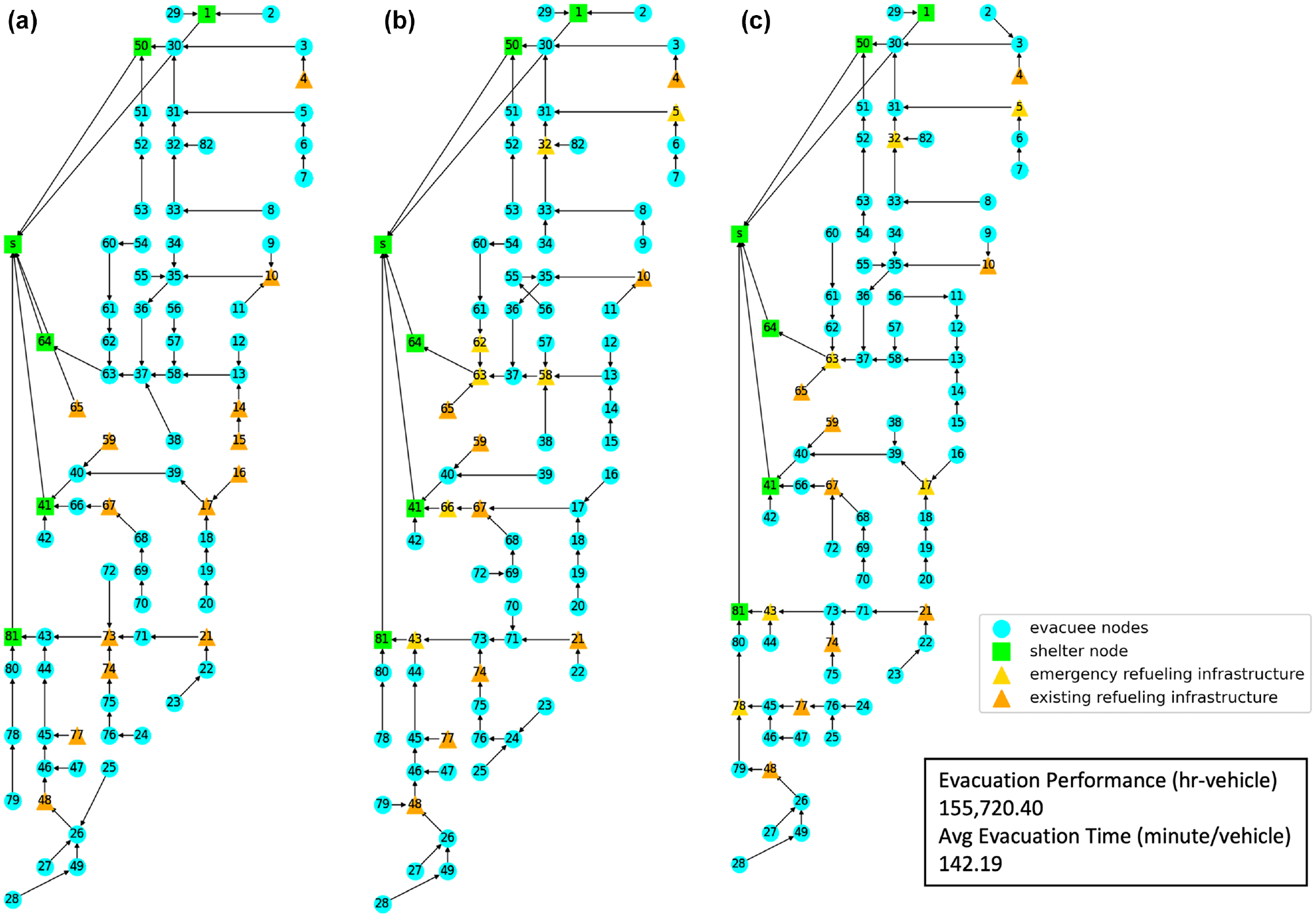
Optimal deployment of emergency refueling stations for Case A: (a) type I vehicles, (b) type II vehicles, and (c) type III vehicles.
Figure 7 presents the deployment plan for each vehicle type in Case B, where the evacuation demand of type II vehicles dominates the market. We observe that no emergency refueling stations are needed to support the evacuation of type I vehicles because they have a long driving range. We deploy seven emergency refueling stations for type II vehicles. For the case of type III vehicles, we deploy five emergency refueling stations, which are fewer compared with Case A. When the vehicles with shorter driving ranges dominate the vehicle shares in the network, fewer emergency refueling stations are needed as we can optimize the evacuation routing to better support the vehicles’ range-limiting specifications.
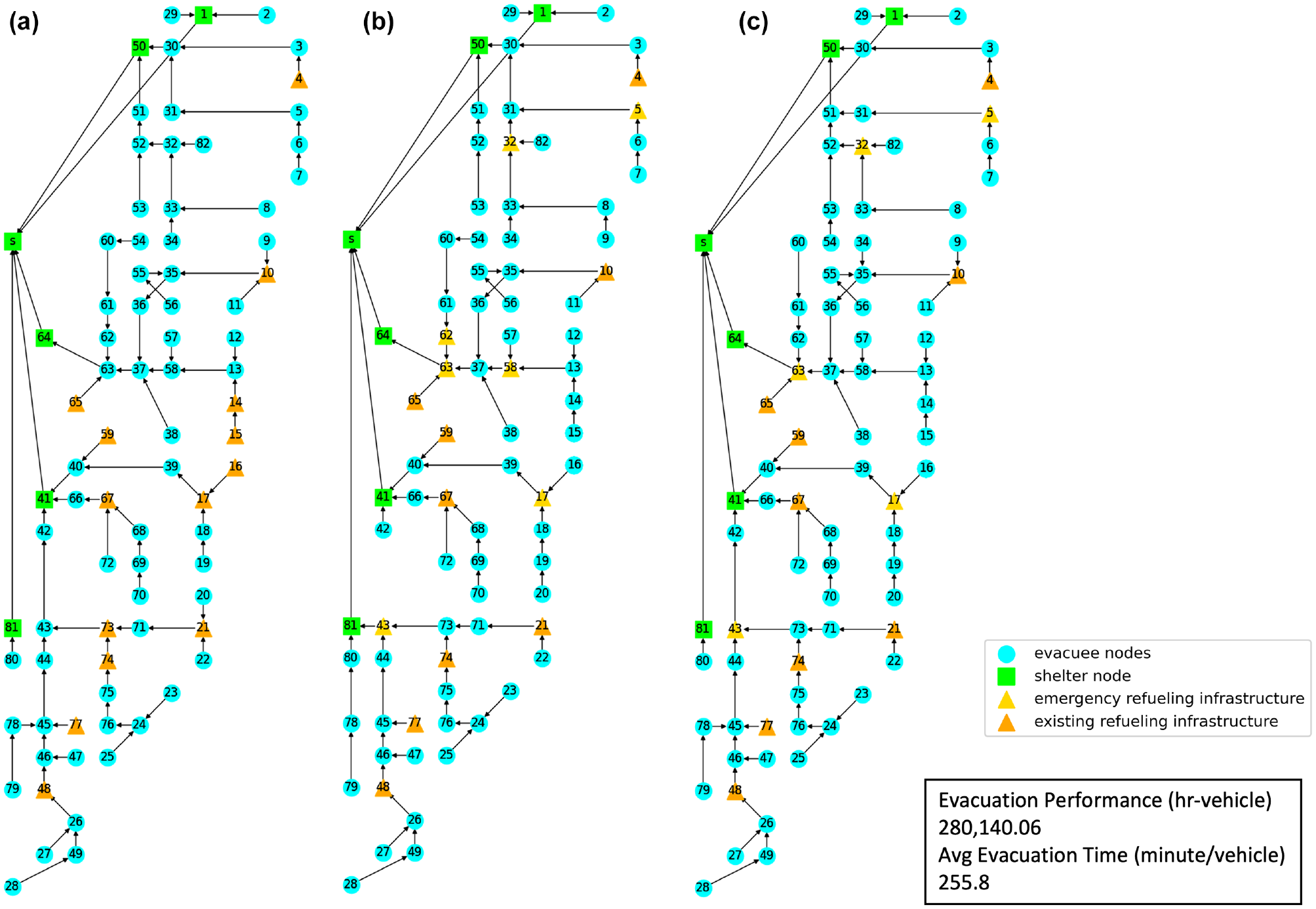
Optimal deployment of emergency refueling stations for Case B: (a) type I vehicles, (b) type II vehicles, and (c) type III vehicles.
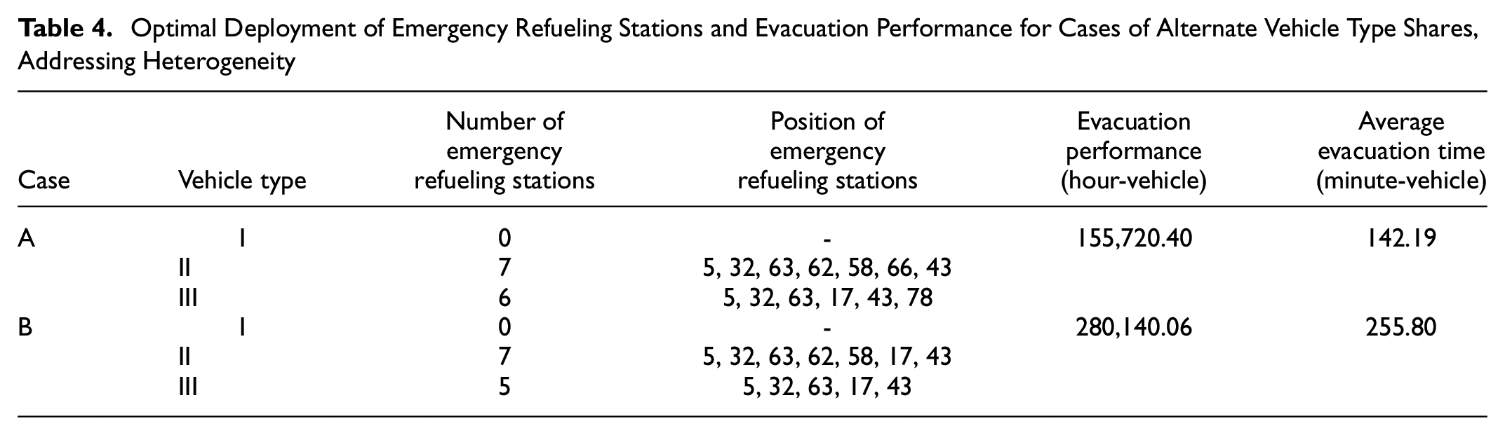
The evacuation routing is the same for the three vehicle types and the case with a single vehicle with range of four hops in Figure 5a. When the population share of type II vehicles is the majority, the evacuation route better accommodates this vehicle type to achieve the system optimum. Since types I and III have larger driving ranges, this evacuation route plan is also feasible for those vehicles, resulting in the same evacuation routing. However, the total system evacuation performance worsens by 80% compared with Case A. The result is expected since vehicle types II and III have shorter ranges and larger population distributions in the network compared with Case A. Note that the optimal deployment for type II vehicles only was already shown in Figure 5a, and for type III only in Figure 5b. From Table 2 it can be seen that the evacuation times for type II vehicles with a range of four hops and type III with five hops have worsened, by on average 260 min per vehicle, because of their limited driving range. For Case B, therefore, total system evacuation performance is expected to worsen significantly compared with Case A because of the limited driving ranges and larger population shares of vehicle types II and III (Table 4).
Optimal Deployment of Emergency Refueling Stations and Evacuation Performance for Cases of Alternate Vehicle Type Shares, Addressing Heterogeneity
Conclusion
The adoption of alternative fuel vehicles has grown rapidly in the USA ( 47 ) with governmental support ( 17 , 18 ) that incentivizes ownership of such vehicles. Their advent challenges conventional evacuation route planning practices ( 10 , 11 ). Strategic placement of alternative refueling stations can help reduce the vulnerability of alternative fuel vehicles and improve their evacuation times before imminent disasters ( 10 , 15 ). To date, very few studies have focused on deploying emergency alternative refueling stations that support the evacuation routing for alternative fuel vehicles.
This paper presents an alternative refueling station location model, based on a location-routing problem, to deploy emergency refueling stations optimally to support evacuation routing. We use a Benders-inspired decomposition procedure to solve the location problem and a matheuristic branch-and-price method to design evacuation routes with hop betweenness constraints. We present the numerical experiments in the South Florida transportation network to evaluate the role of alternative fuel vehicle specifications and vehicle heterogeneity on the deployment plan.
The experiments show that the optimal deployment of emergency refueling stations depends on the bounds of the different vehicles’ driving ranges. The refueling stations in the model are deployed to accommodate the longest evacuation path in the evacuation route. As we increase the driving range of vehicles, the emergency refueling stations can be located with greater distance between them, resulting in a reduced number of deployed stations. Vehicle heterogeneity results in deployment trade-offs. When the vehicle fuel type with a larger driving range dominates in the network, this fuel type will dominate the evacuation route designation based on the system’s optimization. The evacuee population that uses vehicles with lower range specifications would require more emergency refueling stations to support such evacuation routing. When vehicles with a shorter driving range dominate the population share, fewer emergency refueling stations are needed to support their evacuation routing. Emergency planners must strategically deploy emergency refueling stations to support evacuation planning considering the vehicles’ fuel types and their respective shares in the network.
Limitations of this paper that need to be addressed in future studies include accounting for the refueling station capacity, refueling delay, and queueing near stations during the evacuation. The current model assumes that every refueling station has the capacity to serve all incoming vehicles, without any queueing and delaying considerations. However, alternative fuel infrastructure might have a limited number of refueling hoses or charging ports to accommodate evacuees’ vehicles, which could result in queueing at a refueling infrastructure node. Integration with queueing models and balancing fuel demand and supply modeling might fulfill this goal. Furthermore, the current model assumes that the refueling rate for each fuel type depends on the station type and that every vehicle would be compatible with the refueling station provided. However, the refueling rate could depend on the refueling station type, connector/hose type, and vehicle type.
Supplemental Material
sj-pdf-1-trr-10.1177_03611981231171156 – Supplemental material for Refueling Station Location Model to Support Evacuation of Alternative Fuel Vehicles
Supplemental material, sj-pdf-1-trr-10.1177_03611981231171156 for Refueling Station Location Model to Support Evacuation of Alternative Fuel Vehicles by Denissa Sari Darmawi Purba, Simon Balisi and Eleftheria Kontou in Transportation Research Record
Footnotes
Acknowledgements
This research was partially supported by the Illinois-Indiana Sea Grant Faculty Scholar Program.
Author Contributions
The authors confirm contribution to the paper as follows: study conception and design: E. Kontou, D. S. D. Purba; data collection: D. S. D. Purba, S. Balisi; analysis and interpretation of results: D. S. D. Purba, E. Kontou, S. Balisi; draft manuscript preparation: D. S. D. Purba, E. Kontou. All authors reviewed the results and approved the final version of the manuscript.
Declaration of Conflicting Interests
The author(s) declared no potential conflicts of interest with respect to the research, authorship, and/or publication of this article.
Funding
The author(s) disclosed receipt of the following financial support for the research, authorship, and/or publication of this article: This research was partially supported by the Illinois-Indiana Sea Grant Faculty Scholar Program.
Supplemental Material
Supplemental material for this article is available online.
The authors confirm their full personal access to all aspects of the writing and research process and take full responsibility for the paper. The opinions expressed in this paper are those of the authors and not those of the sponsors. This paper does not constitute a standard, specification, or regulation.
References
Supplementary Material
Please find the following supplemental material available below.
For Open Access articles published under a Creative Commons License, all supplemental material carries the same license as the article it is associated with.
For non-Open Access articles published, all supplemental material carries a non-exclusive license, and permission requests for re-use of supplemental material or any part of supplemental material shall be sent directly to the copyright owner as specified in the copyright notice associated with the article.