
Abstract
A numerical simulation study on the combination of a Darrieus and a Savonius wind turbine is conducted. Hybrid T-II, T-III, and T-IV turbines are suggested with the same Darrieus turbine T-I. In the T-II and T-III, the Savonius turbine is at the center of the Darrieus turbine, whereas in the T-IV, the Savonius turbine is above the Darrieus turbine. The T-III Savonius turbine has half the radius of that of the T-II turbine. Results reveal that variations of the power coefficients, Cp with the tip speed ratio, TSR for the hybrid turbines have different slopes. It is observed that Cp increases with increasing TSR for the T-II and T-IV and does not decrease for the range of TSRs considered, in contrast with the Cp behavior of the T-I. The proposed hybrid T-IV turbine has also a larger Cp than the T-I turbine at the highest TSR.
Introduction
Wind energy plays an important role in global energy production from renewable energy sources. The overall world’s wind energy potential is estimated to be about 2700 trillion watts, which shows the potential impact of wind energy. Other important advantages of wind energy are its low environmental impact, creating local wealth and employment, and its lower price, compared to many other energy sources for electrical energy production, even some fossil fuels. Considering the above-mentioned points, wind energy can be claimed as one of the well-established clean energies, which has the lowest start-up cost, even in comparison with other clean energy sources.
Wind turbines convert wind kinetic energy to mechanical power and subsequently to electrical energy (Graham, 1999). Wind turbines are generally categorized into horizontal-axis wind turbines (HAWTs) and vertical-axis wind turbines (VAWTs). Traditionally, HAWTs dominated the wind power industry, but, nowadays the use of VAWTs has become more widespread in urban areas. One foible of HAWTs is that the blades use the aerodynamic lift to spin, hence they should always face toward the wind, which requires the use of expensive mechanical systems. Instead, VAWTs use lift, drag, or a mixture of the two so they can use wind coming from any direction. In addition, due to their vertical orientation, the required mechanical equipment can be placed closer to the ground, which substantially reduces maintenance costs, size, and unpleasant noise. Besides, VAWTs have a better self-starting ability at lower wind speeds. Due to these facts, VAWTs are considered more operational for urban areas with slower and more turbulent wind flows (Stathopoulos et al., 2018; Winslow, 2017). Many studies have been performed to understand the flow dynamics around VAWTs to improve their efficiency. Some recent examples of such studies are summarized in the following.
The effect of airfoil asymmetry on the efficiency of a VAWT was experimentally investigated by Islam (2008) and was found that the efficiency with symmetric airfoil sections was higher than with asymmetric ones. Wang et al. (2010) investigated the aerodynamic performance of a VAWT with straight blades at different wind speeds. Improving the self-starting capability of VAWTs was performed by Beri and Yao (2011), Howell et al. (2010) conducted numerical and experimental research on small VAWTs to examine the blade surface roughness effect on their performance. The effect of the number of blades on the performance of a straight-bladed VAWT was studied by Castelli et al. (2012). It was found that the efficiency of three-bladed VAWTs was higher than that of four or five-bladed ones. Gupta et al. (2008, 2012) examined the performance of two blades of a Savonius turbine with five overlaps of 16.2%, 20%, 25%, 30%, and 35%, among which, the case with 16.2% overlap had the highest output power. Stall dynamics at different azimuthal angles of a VAWT were studied by Buchner et al. (2015) through experiments and numerical simulations using unsteady RANS. A reasonable agreement between the two approaches was observed with differences in flow separation location at the highest tip-speed ratio (TSR). Ionescu et al. (2015) used computational fluid dynamics to conduct a study to increase the efficiency of wind turbines by attaching a flap to the end of VAWT blades. It was found that changing flap angles up to a certain degree could improve the performance of the VAWT. To determine optimal pitch angles, Abdalrahman et al. (2017) examined the aerodynamic performance of a straight-bladed Darrieus VAWT at different pitch angles and TSRs, using the finite-volume method. For each studied case, the power coefficient,
It is important to note that, stability is a crucial factor in the design, operation, and overall performance of wind turbines. The stability in wind turbines refers to the ability to maintain a steady and controlled operation under various environmental conditions. Structural stability, aeroelastic, and aerodynamic stabilities among other different aspects of stability are important to the turbine operation. There has been some interesting research on the stability of vertical axis wind turbines, such as Owens and Griffith (2014) and Wang et al. (2023).
There exist different extensive review works on the history of VAWTs, see for example the work by Möllerström et al. (2019). The most commonly used VAWTs, in general, are divided into Savonius and Darrieus types. The differences between the two geometries have caused differences in efficiency and ability to self-start. Savonius blades with concave and convex surfaces work with drag force due to the wind. Due to the proximity of the blades to the axis of rotation, Savonius turbines do not require high torque to start rotating and could even operate at low wind speeds. However, their efficiency is lower than the Darrieus turbines. Unlike the Savonius, Darrieus turbines operate with lift force and can have an efficiency of about 0.5. Despite this advantage, due to the blade location, away from the axis of rotation, these turbines require high torque to rotate and operate at higher wind speeds. One way to overcome this disadvantage is to use a control system to measure wind speed, but this system reduces power generation capacity and is costly. So, it is a necessity to design a Darrieus turbine with the ability to self-start (Kumar et al., 2018). Thus, hybrid configurations, employing Savonius turbines with self-start ability and helical Darrieus turbines with higher operating efficiency could potentially lead to the development of a hybrid wind turbine with both advantages.
In the present study, first, a single helical Darrieus wind turbine is numerically investigated. Then, by adding Savonius blades to the Darrieus turbine, three hybrid wind turbine structures are proposed and their performances are thoroughly examined and compared. Significant and novel results are achieved in terms of design and performance analysis of the hybrid VAWTs.
Geometry and mesh
Figure 1 shows the schematic of the reference helical Darrieus VAWT of Cheng et al. (2017), named T-I turbine, and the three hybrid Darrieus-Savonius geometries namely, T-II, T-III, and T-IV, designed in the present study with similar helical Darrieus blades as T-I, but with different layouts for the Savonius blades. The four-bladed T-I turbine, which serves as the validation test case, has a NACA0018 blade profile with a chord length of 0.1 m, rotor radius of 0.21 m, and blade height of 0.54 m. The Savonius geometry of the T-II, T-III, and T-IV turbines is located at the center of the hybrid wind turbine. The general idea of this arrangement is based on the laboratory structures presented by Siddiqui et al. (2018). With this in mind, the Savonius blades are at the center of the Darrieus blades in turbine T-II. The height of the Savonius blade is 0.2175 m and its radius is 0.13 m. In turbine T-III, the Savonius blades are also at the center of the Darrieus blades, but their radius is half of that of the T-II turbine. In the T-IV turbine, the Savonius blades are positioned above the Darrieus blades and the radius of the Savonius turbine is the same as the T-II turbine.
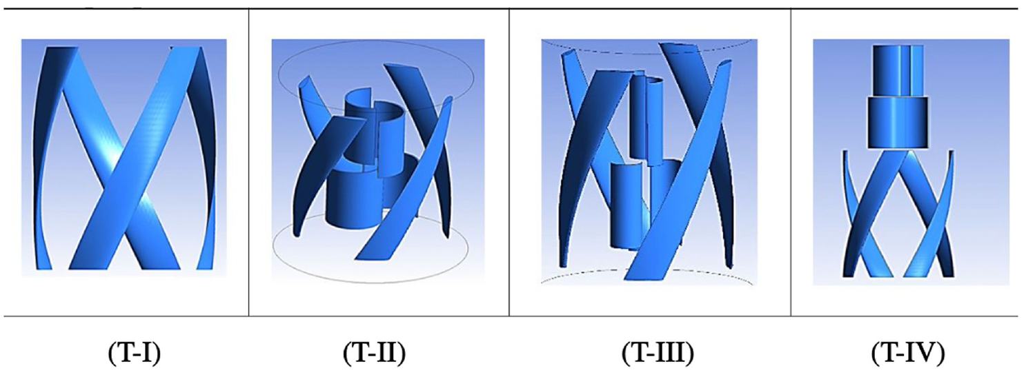
Schematic of the helical wind turbine T-I (Cheng et al., 2017) and the three hybrid turbines, T-II, T-III, and T-IV, designed in the present study.
In the results and discussion section, performances of the T-I, T-II, T-III, and T-IV turbines are compared and the most efficient geometry is introduced, based on the
A hybrid tetrahedral and structured boundary-layer-type mesh is employed, see Figure 2(c). To properly resolve the boundary layer, 20 cells, in the form of a structured hexahedral mesh, span the boundary layer in the wall-normal direction. The first wall-adjacent cell has an average wall distance of less than
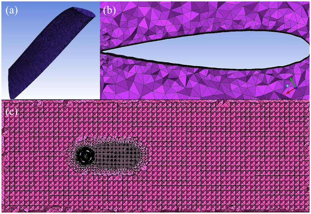
Representation of the surface mesh on the Darrieus blade (a), boundary layer mesh at a cross section of the Darrieus blade (b) and a horizontal section of the volumetric mesh at the mid hight of the turbine throughout the domain (c) for the T-II turbine.
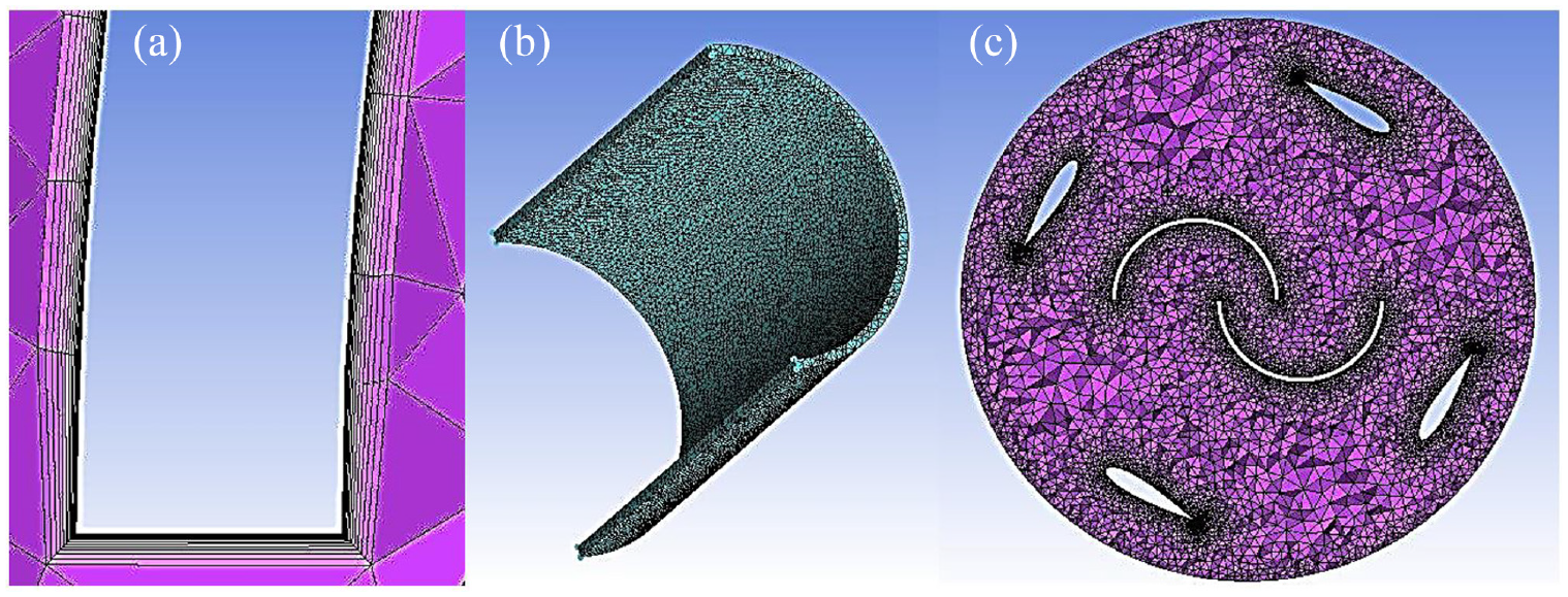
Sections of the volumetric mesh used for the T-II turbine. Boundary layer mesh (a), surface mesh, (b) and volumetric mesh at the mid-section (c).
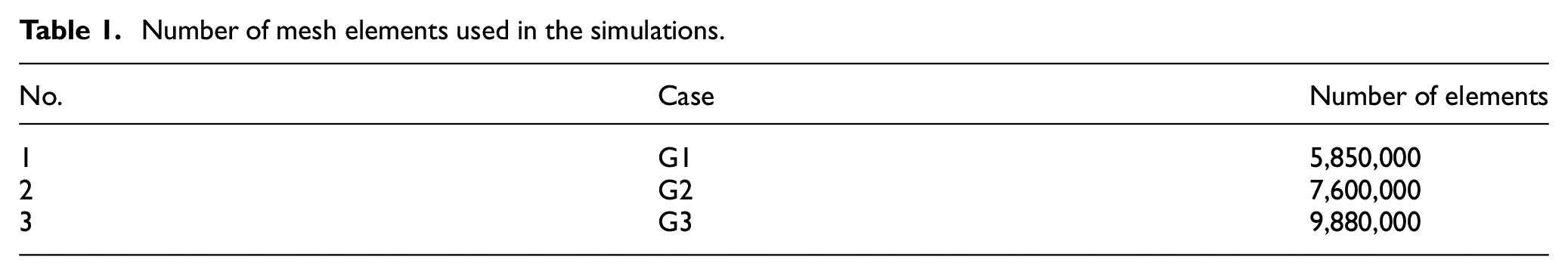
Number of mesh elements used in the simulations.

Comparison of the static pressure distribution along 50% span and 60° blade angle for grid : G1,  : G2, and
  : G3.
: G3.
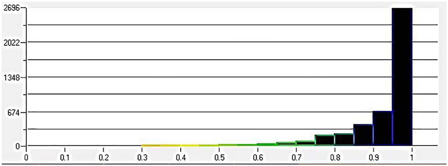
Grid quality diagram for the G2 grid.
Governing equations and numerical method
The governing equations are the unsteady Reynolds-averaged continuity and Navier–Stokes equations, which in the incompressible form, using the summation convention, read


where,

where,
Choosing an appropriate turbulence model is crucial for the successful numerical simulation of a VAWT, which can significantly affect the accuracy of numerical predictions, such as the pressure coefficient. The transition-SST model with standard model coefficients is employed in the current simulations. The transition-SST model uses the SST
Domain layout, size, and boundary conditions are similar to those of the study by Cheng et al. (2017), see Figure 6. The domain extent and position of the wind turbine are chosen such that the inlet and outlet boundary conditions do not affect the numerical predictions. The domain is divided into a stationary and a rotating part, which encloses the wind turbine. The sliding mesh method is used to connect the rotating and non-rotating parts of the domain, as suggested by Roychowdhury (2020). The matching method of the FLUENT software was used for the interface between the rotating and stationary parts of the domain. A constant 9 m/s velocity inlet boundary condition with a constant turbulence intensity of 1.5% is used at the inlet and a constant 1 atm pressure was employed at the outlet, see Figure 6.
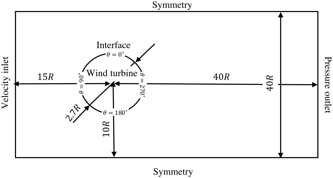
A horizontal cross-section of the schematic view of the domain, showing the layout, size, boundary conditions, and relative angle of the blades
Results and discussion
Tip-speed ratio (TSR) is used as the parameter in the analysis of the wind turbines. It is defined as the ratio of the blade tip speed to the free-stream velocity, written as (Ragheb and Ragheb, 2011)

where,
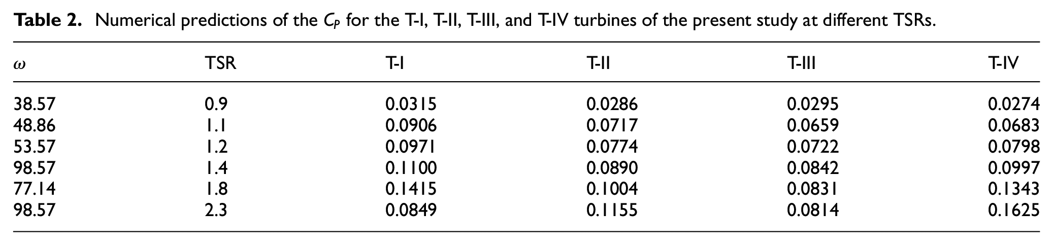
Numerical predictions of the
Validation of the current numerical method
A comparison of the static pressure distribution over the T-I turbine blade, at 50% blade span and rotation angles
Static pressure distribution over the 50% blade span of the T-I turbine at angles and numerical results of Cheng et al. (2017): .
Figure 8 shows the static pressure distribution over the mid-section of the blade for 90° rotations of the T-I turbine at TSR = 1.2. The figure demonstrates that the dynamic stall phenomenon, which has a complex physics, is captured in the current numerical simulations. It should be noted that the dynamic stall process is a phenomenon in wind turbines, during which the lift increases intensively, and performance improves for a short period of time. This continues with a rapid drop of the lift force and as a result, a drop in the overall turbine performance. Then, the boundary layer experiences a recovery process. The dynamic stall limits the operation of the VAWT and is known to be more intensive at lower TSRs. For brevity, pressure contours will not be examined for the other three cases.
Static pressure distribution over the mid-section of the T-I turbine at TSR = 1.2 for 90° blade rotation, showing the dynamic stall phenomenon, different panels show the blade at angles
Static pressure predictions
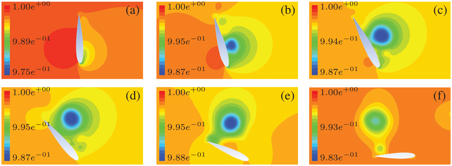
To visualize the Savonius and Darrieus turbine flow interactions, instantaneous pressure contours at TSR = 0.9 and 1.2 are given at the mid-section of the T-I, T-II, T-III, and T-IV turbines in Figure 9. Pressure distribution over the T-I turbine shows the regular pressure distribution over a Darrieus turbine, see Figure 9(a) and (b). The figure shows small pressure differences between the lower and higher TSRs.
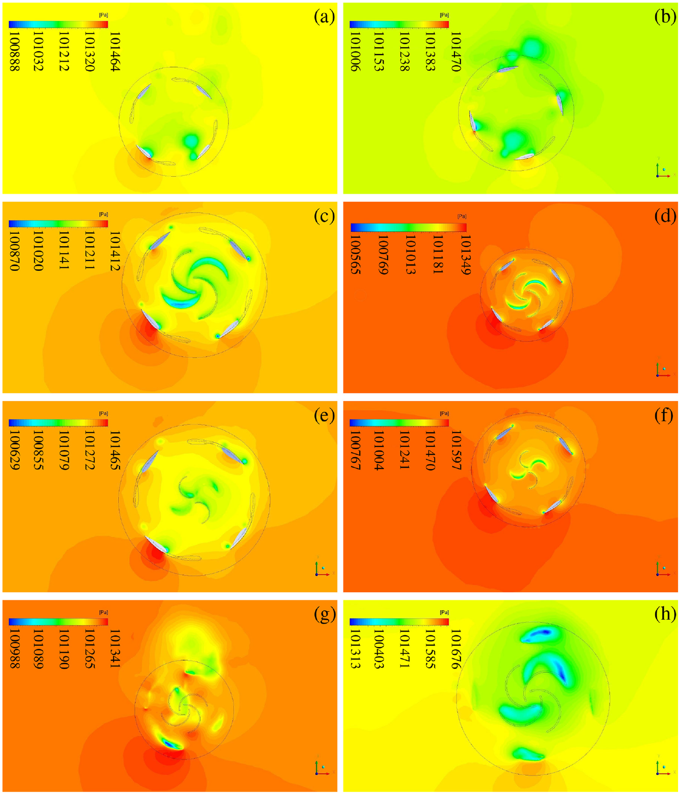
Static pressure distribution at the mid-section of the Darreius turbine of the: (a) T-I @
When the Savonius turbine is placed inside the Darrieus turbine (T-II and T-III turbines) pressure interactions are observed between the two turbines. The interaction is more intense in the T-II turbine, which has a larger radius, compared with the T-III turbine with the smaller Savonius turbine, compare Figure 9(c) and (d) with Figure 9(e) and (f).
Figure 9(g) and (h) show the pressure distribution at the mid-section of the Savonius blades of the T-IV turbine, where the Savonius turbine is placed on top of the Darrieus turbine. As is expected, an interaction between the two turbines is not observed.
Figure 10 shows a 3D view together with the top, bottom, and mid-section perspectives of the static pressure distribution for the hybrid Darrieus-Savonius wind turbine T-III. The 3D view of the pressure field is visualized to offer a more comprehensive view of the pressure field, throughout the entire turbine surface. In Figure 10(a), it is evident that the pressure level is comparatively lower in the inner Savonius turbine than in the outer helical Darrieus turbine. An intriguing observation reveals the presence of highly intense high- and low-pressure regions at the tip of the helical blades. Furthermore, as previously mentioned, notable pressure interactions can be observed between the Savonius and Darrieus turbines. Specifically, on the inner side of the Savonius turbine, discernible low-pressure regions are apparent, as depicted in Figure 10(c) and (d), which correspond to the mid-section view and the bottom-section perspective, respectively. Additionally, the pressure distribution at the bottom section of the hybrid turbine exhibits more pronounced pressure differences, as shown in Figure 10(d).
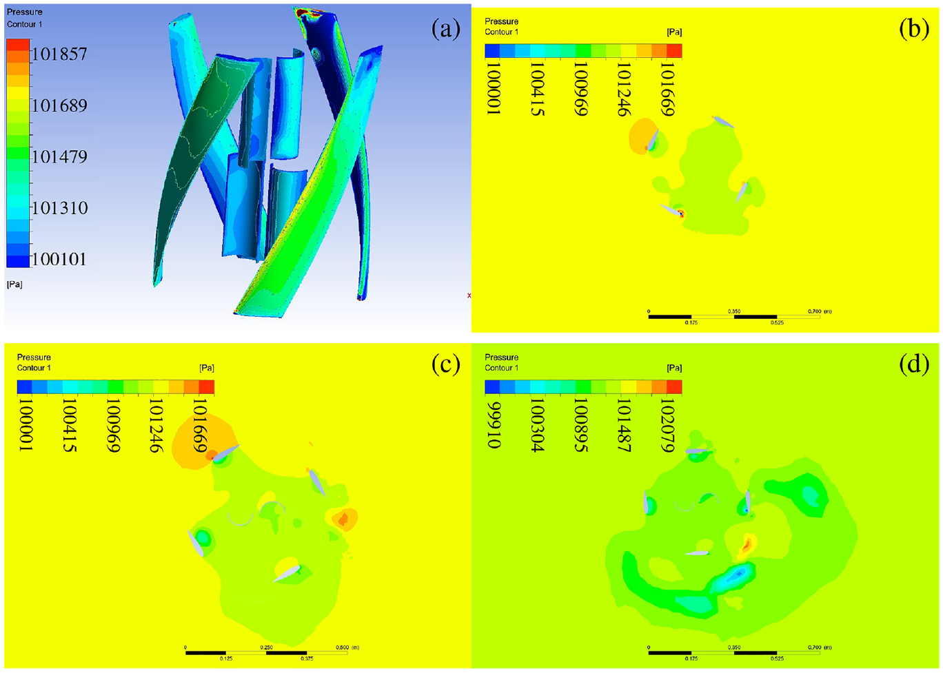
Static pressure distribution of the hybrid Darrieus-Savonius wind turbine: (a) the 3D view, (b) the top view, (c) the mid-section view, and (d) the bottom view of the pressure field.
Blade surface static pressure is also given at 30%, 50%, and 70% blade span in Figure 11 for the helical Darrieus blades of the T-IV turbine at rotation angle
Static pressure distribution over blade sections at 30% span , 50% span , and 70% span of the helical blade at
Effect of the Savonius turbine position on the power production
To assess the power production by the hybrid turbines, the power coefficient,

A comparison between the predicted
Comparison of the power coefficient, , T-II  , T-III , and T-IV
  turbines with numerical simulations
  and experimental measurements
  of Cheng et al. (2017).
Adding the Savonius turbine in the T-II, T-III, and T-IV configurations leads to a different behavior in the
It should also be noted that the hybrid T-II turbine has a slightly higher
Another important point in the experimental studies of hybrid Darrieus-Savonius wind turbines is related to the vibration effects of wind turbine blades, see the experimental work of Siddiqui et al. (2018). These vibrations could have a larger effect on the performance of the hybrid T-IV turbine, compared with the other geometries. Because in this geometry, the Savonius blade is positioned above the helical blade, and this structure at high rotation speeds could lead to a significant increase in blade vibrations.
Conclusions
The present study examined three different combinations of Savonius and helical Darrieus wind turbines to investigate the effect of the Savonius turbine position and radius on the overall aerodynamic performance of the hybrid wind turbine. The most optimal hybrid vertical wind turbine configuration was introduced.
According to the results, choosing the best case depends on the goal of adding the Savonius turbine. If it is merely due to performance, the addition of the Savonius turbine is only justified if the turbine is operating at tip speed ratios higher than 1.8. The best performance in this interval was observed when the Savonius turbine was positioned on top of the helical Darrieus turbine. The main reason for this difference in the
Footnotes
Declaration of conflicting interests
The author(s) declared no potential conflicts of interest with respect to the research, authorship, and/or publication of this article.
Funding
The author(s) received no financial support for the research, authorship, and/or publication of this article.