
Abstract
To increase the power yield, wind turbines have significantly grown in the last decades. Today, this growth is more and more limited by the weight of the structures and fatigue loads. To compensate these loads, especially flapwise root bending moments, trailing edge flaps can be used. They can change the lift of the blade with little delay to equalize the aerodynamic lift and by this reduce the fatigue amplitude. Such a trailing edge flap has been designed, developed, built and experimentally tested. It uses a flexible, morphing design to seal the entire mechanics against environmental influences, such as rain, dust, or insects. Therefore a design made from glass fiber reinforced plastics in combination with elastomer materials is used. In this paper the design process from the concept to two consecutive demonstrators is presented. Both are tested in the laboratory for their morphing characteristics.
Introduction
The rotor height and diameter of wind turbines have continuously increased within the last years with the aim to increase the energy yield per site. A greater rotor diameter as well a higher rotor hub allow an increased maximum power and the operation within higher wind speeds.
Since wind turbines are operating in unsteady conditions over years or decades, fatigue loads play a key role in the design of rotor blades. Load cycles, especially for turbines in wind parks facing wakes of other turbines, can encounter more than
Due to the fact that modern wind turbines use pitch control to ensure a constant rotation speed and power output at different wind speeds, the obvious solution to flapwise fatigue loads is to reduce the aerodynamic excitation with the pitch system. This so-called individual pitch control (IPC) was then investigated and simulations predict a reduction of the blade bending load in flapwise direction of up to 25% using IPC as shown in Larsen et al. (2005). Although seemingly easy to implement, the disadvantage of IPC arises from the high mass of the whole rotor blade, which has to be adjusted with at least rotation frequency of the turbine. This required big pitch actuators and durable bearings at the rotor hub.
Therefore, a different method has been proposed: Individual flap control (IFC), where a trailing edge flap is mounted in the outer part of the blade. Deflecting this flap can achieve a comparable effect on lift and bending moment of the blade as tilting the whole blade with the pitch drive. Due to the lower mass of the flap compared to the whole blade, the actuator can be built significantly smaller and the flap can be controlled much faster.
This paper will focus on the concept and the design of two trailing edge demonstrators. At the beginning, a concept for a flexible trailing edge is derived. Based on this concept, the “concept demonstrator” is designed with a chord of
Trailing edge flaps for wind rotor blades
Trailing edge flaps as a tool to change the lift of an airfoil are not fundamentally new since fixed wing aircraft use these as control surfaces on wings and stabilizers. The basic idea is to influence the lift coefficient of an airfoil with the flap by changing the camber. About 30 years ago, research started to use this principle to improve helicopter rotors by reducing noise and vibration, which are in this case caused by blade vortex interactions. Noise and vibration reduction would allow longer inspection intervals and higher acceptability in urban regions. To achieve this, a trailing edge flap is proposed on the outside of the blade, which can avoid blade vortex interactions causing most of the noise and vibration issues. For fast actuation speeds, piezoelectric transducers in the form of bending bimorph actuators (as e.g. used in Hall, 1990 or Koratkar and Chopra, 1997) or stack actuators have been investigated (e.g. Straub et al., 2001 or Lee and Chopra, 2001). To avoid the issues of high aerodynamic and centrifugal loads on piezoelectric stacks or bending actuators, a second concept has been investigated: Active twist blades, where the whole blade is twisted along its span. Therefore different concepts have been investigated at DLR (Monner et al., 2008) in a model scale of 1:2.5. As a result it could be found that applying piezoelectric patch transducers to the skin of the blade in a
Since twisting wind rotor blades would generally achieve the same effect on the lift in the outer blade as on helicopter blades, the same technologies can be used theoretically. Practically, active twist is not feasible since wind rotor blades are too stiff for a realistic amount of piezoelectric transducers due to their scale and skin thicknesses. Therefore, trailing edge flaps are investigated. When looking at helicopters, they have been discarded due to the high centrifugal loads, which can reach up to 1000g. In contrast, wind turbines only show less than 10 g at the blade tip. Therefore trailing edge flaps can be considered for actively controlling lift and hereby root bending moments of wind turbines.
The first investigations in this realm have been performed by the National Renewable Energy Laboratory (NREL) in the USA, where trailing edge devices have been investigated for different applications, such as aerodynamic brakes (Migliore et al., 1995), speed control devices (Miller, 1995) or as a means of power regulation and load mitigation (Stuart et al., 1996). There the potential for influencing drag and lift with a trailing edge device as well as the possibility to use this influence to control power and gust loads could be shown.
Since the growth of wind turbines has already been obvious and the related issues concerning control and fatigue were already foreseeable, two research initiatives began investigating active flow control methods for wind energy. The first one was situated at the Sandia National Laboratories (SNL) in the US, where the research in Europe gathered around Technical University of Delft (TU Delft) and the Danish Technical University (DTU) in Risø. There, a lot of different approaches have been discussed in the first place to determine the most promising solutions. Several papers by Barlas et al. (2006), Barlas and Van Kuik (2007, 2010) from TU Delft as well as Van Dam et al. (2008) from SNL discuss a wide variety of possibilities from span changes of rotors to different active flow control techniques, such as microtabs, trailing edge flaps, active twist, and much more.
At TU Delft, these preliminary considerations lead to wind tunnel tests of a flexible trailing edge flap based on piezoelectric bending actuators, where a positive effect on the root bending moments could be demonstrated in open loop, as well as in closed loop control (Barlas et al., 2008; van Wingerden et al., 2008). A comparable setup has been proposed within the ADAPWING project at DTU (Buhl et al., 2005, 2007), where the same piezoelectric transducers have been used for a flexible trailing edge in a wind tunnel test of a
At SNL, considerations have been undertaken to investigate the load reduction behavior of trailing edge flaps for wind turbines (Berg et al., 2009) or as shown in a cooperation between SNL and TU Delft in Resor et al. (2010), where a reduction of flapwise root bending moments of up to 30% is suggested for the presented flap setup. Based on these promising results, a free field experiment has been set up using a three bladed wind turbine with
To further investigate the effect of trailing edge devices, a flexible trailing edge has been designed and built at DTU for a free field test within the INDUFLAP project. This uses an elastomer design, where the trailing edge contains different chambers, which are pressurized with air as described in Andersen et al. (2013). To minimize the effort for the free field test, a rotating test rig has specially been set up (Barlas and Aagaard Madsen, 2014). Since this will also come into effect with the topics of this paper, it will be further considered in detail later. On this test rig, the trailing edge flap has been experimentally measured with the result of a 14% reduction of root moment with an azimuth control of the flexible trailing edge (Barlas et al., 2014). A very recent experimental investigation is described in Gonzalez et al. (2022), where a trailing edge based on the elastomer design used in the INDUFLAP project has been scaled up to a
As a conclusion to this state of the art review, it can be stated that trailing edge devices are a possible solution for the problem of rising fatigue loads of future wind turbines with longer blades and higher hubs. Experimental investigations in wind tunnels and free field test rigs prove the simulated results.
Since many of the presented concepts are hard to implement on fullscale wind turbines, for example piezoelectric transducers, for their weight, limitations to small scale or cost, a concept is needed which is compatible with rotor blade lengths of potentially more than
Trailing edge design and concept demonstrator
General assumptions for concept demonstrator
To be in line with current rotor blades, the general design of the trailing edge is applied to the
According to Oltmann (2015), the trailing edge flap has the most effect in the outer part of the blade, where a span of
To investigate the most critical case, the most outward position is chosen, where the aerodynamic loading reaches its maximum and the design space is minimal. The following dimensions are chosen to derive a flexible trailing edge concept, which will be realized in a small span demonstrator:
Airfoil type: DU08W180
Airfoil chord:
Trailing edge chord: 20% (
Demonstrator span:
Flexible trailing edge concept
From a purely physical point of view, a solid, hinged trailing edge flap seems to be the ideal solution. It is simple to design, simple to build and, from an engineering point of view, proven over nearly 100 years from aviation. Airplanes exclusively use trailing edge flaps as control surfaces, such as ailerons, elevator and rudder. So why is it worth to leave this proven technology to consider morphing trailing edges? In fact, wind turbines differ in some fundamental characteristics from airplanes:
Full time operation in lower troposphere exposed to weather, dust, and insects.
Much higher operation time, load cycles up to
Much longer maintenance intervals.
Production and maintenance cost have to be as low as possible.
Reduced safety requirements, no persons on board.
While some of the mentioned items can be fulfilled with hinged flaps, especially the first aspect is the most challenging: Since wind turbines are placed outside for their whole existence, they will permanently be in contact with the low atmosphere environment. Airplanes in contrast will spend all their cruise flight in the upper atmosphere, where no dust, insects and water are present. Additionally airplanes are checked intensively every few years, where defects in control surfaces are detected and repaired. This has to be avoided for wind turbines.
In contrast to hinged flaps, which always need a gap, morphing allows the design of completely sealed trailing edge devices, where all environmental influences, such as water, dust, insects or other debris can be kept outside the mechanism. This allows for a great reduction of jams, corrosion or wear. For these reasons, a morphing trailing edge is supposed to be the most promising concept for a wind turbine load control device. But how can it look like?
Generally it has to be designed in such a way that a complete sealing is possible. That is why shifting two layers of the upper and lower side of the airfoil (as e.g. shown in Wildschek et al., 2010) is not applicable, since this always requires a gap at the end. Therefore, all concepts known to the author use some kind of elastomers or hyperelastic materials to cope with the high strain, which arise from bending the rear end of the airfoil. To bear the aerodynamic loads and the actuation forces, also some kind of stiff material is needed. This can be arranged in two fundamental ways: Either the stiff material forms a part of the skin as shown in Figure 1(a) or it is the core of the airfoil, like shown in Figure 1(b).
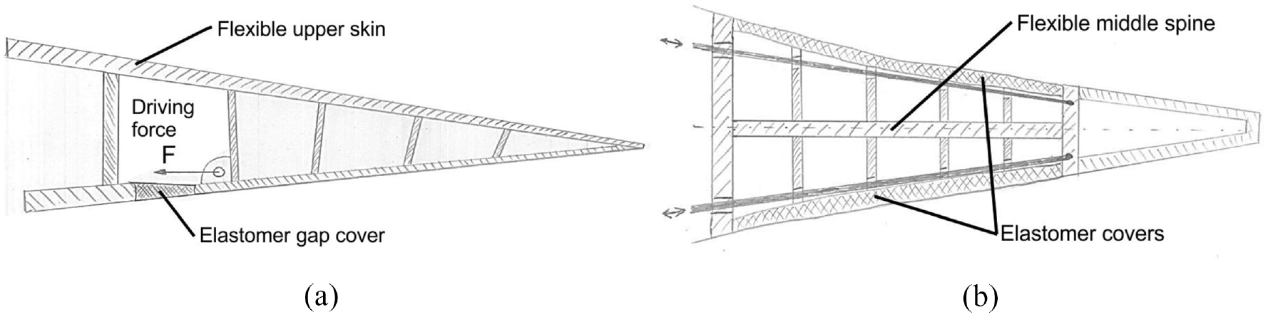
Flexible trailing edge concepts with elastic upper skin (a) and middle spine (b).
The concept of Figure 1(a) has been patended by Vestas in 2008 (Hancock, 2008), whereas the concept in Figure 1(b) is comparable to the one tested by DTU in 2014 (Barlas et al., 2014).
When looking at the concepts, they both have drawbacks. The concept in Figure 1(a) requires comparably high strains within the short elastomer region to allow the required deflection of the trailing edge. This is not the case for the other concept in Figure 1(b), where the elastomer layers are much longer and, in addition, the distance to the neutral fiber is much shorter. The lack of this concept consists in the bonding of the elastomer cover to the central spine. In the solution of Andersen et al. (2013), this is achieved by building the whole trailing edge flap from the elastomer. Since the stiffness and rigidity of elastomers is quite low compared to fiber composites, such a trailing edge would be comparably heavy.
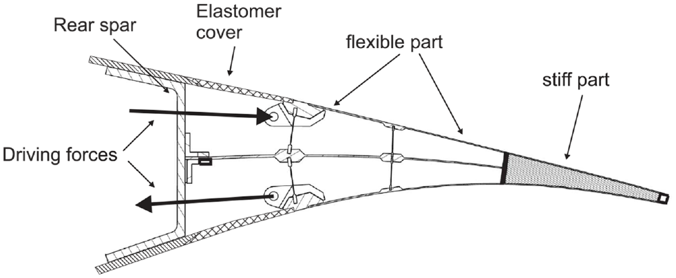
Therefore, a different concept is suggested, which can be seen as a combination of both principles shown in Figure 1. It uses a central spine made from glass fiber composite and, to avoid the challenging bonding of the elastomer skin at different places, only an elastomer cover in the foremost region of the airfoil. In the rear part also a glass fiber skin is used. The elastomer cover is only used in the first segment of the flexible part. This allows to keep the strain below 100% and the number of attachment points of the elastomer at the minimum with only two contact points. The principle of this concept is shown in Figure 2. To actuate the trailing edge, the driving forces are introduced into the fiber composite outer skins, which are stiff enough to transfer these forces to the entire flexible part of the trailing edge. By this, a precise control is possible and there is no need for further kinematics behind the elastomer covers. In Figure 2, the driving forces are marked with “F” and arrows.
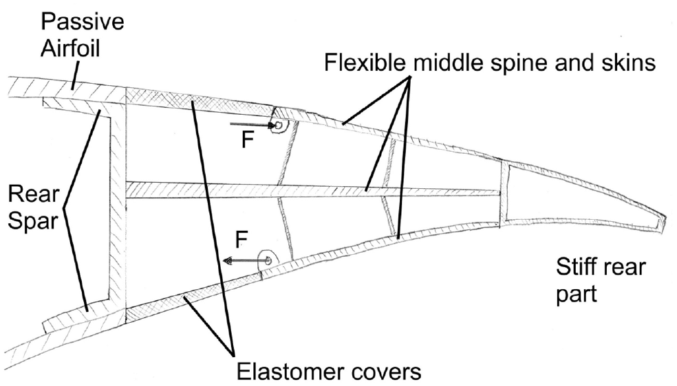
Basic principle of flexible trailing edge concept.
To prove the general applicability of this idea to wind turbines, a 2D finite element model was created. It uses the DU08W180 airfoil, which is applied in the outer part of the reference rotor blade defined in the SmartBlades project. For this first test, a relative chord of 20% is modeled with a total chord of
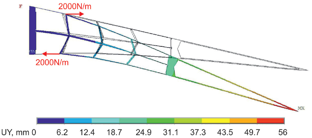
2D finite element based displacement plot of flexible trailing edge concept.
As visible in Figure 3, the 2D simulation proves the general applicability of this concept for a morphing trailing edge. The deformation is visible over the whole chord of the flexible part.
Driving mechanism
In Figures 2 and 3, the actuation of the trailing edge is only represented by forces. For a real demonstrator, this is not a practicable way, so a driving mechanism is needed, which links a servo motor or something comparable to the trailing edge. In the first place, one may think of cables or wires for this application. This has the drawback, that they are only able to apply pulling forces. Because an actuation has to incorporate a positive and negative deflection, a force needs to be applied on upper and lower side of the trailing edge, respectively. Reducing the actuation to only pulling force leads to high force requirements on the driving mechanism attachment points and which in turn leads to heavy and bulky designs to spread the forces into the fiber material. From a weight aspect, it would be much better to divide the force to reduce the structural requirements. Therefore, bars are needed which are able to transfer tension, compression and lateral forces.
A second aspect for the design of the driving mechanism arises from the degree of freedom, which is used to deform the trailing edge. Since all cells in the trailing edge are quadrilaterals, they intentionally lack shear stiffness, since all shear has to be transferred in the skins and in the central spine. Especially in the first cells, which are covered by the elastomer, all shear load has to be compensated by the central spine. Thus it would be helpful to expand the driving force at the rear end of the first cells by shear forces in flapwise direction additionally to the already presented driving forces in chordwise direction.
The third point to consider is the load distribution between the upper and the lower side of the airfoil. It is useful to avoid the necessity for a controlled force at each point. Therefore a mechanism has to be found, which is able to drive each of the two points with chordwise forces, can apply a flapwise shear force and provides a kinematically defined force distribution between both points with only one driving force.
Figure 4 shows the design principle of the kinematics, which fulfills all mentioned aspects. It basically consists of six beams, which are interconnected with eight joints. The joint marked “H” in Figure 4 is connected to the rear spar whereas the joints “D” and “E” link the long beams to the skin of the trailing edge.
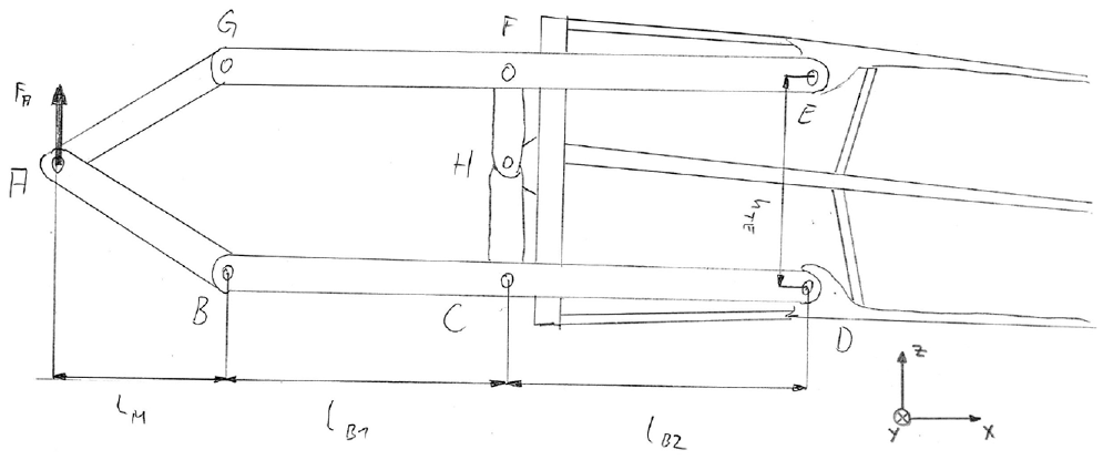
Principle of trailing edge kinematic concept.
To actuate the trailing edge with the proposed kinematic structure, only one driving force (
Assuming the two long beams (joints B–D and E–G) to be parallel, the track from joint B to D to be perpendicular to the long beams and the two beams at the front (A G and A B) to have the same length, the chordwise (“x”) and flapwise (“z”) forces at the joints D and E, where the force is transferred to the skin of the trailing edge, can be calculated as described in equations (1) and (2). Of course this is simplified to one position of the driving mechanism, but it allows a simple calculation of the dimensions as a starting point for detail design.


It is obvious, that by appropriately choosing the beam lengths
Of course deflecting this kinematic structure changes the geometric characteristics and by this also the force ratios. In fact, if the deflection at point A is below one-third of the distance between the beams
For a detailed investigation of the trailing edge, especially for the deflecting fiber composite parts, a finite element model is needed anyway. Thus the driving mechanism will be realized in the model too using beam elements to design it in parallel to the fiber composite part of the trailing edge.
Aeroelastic design process
When designing morphing structures, a fundamental conflict has to be dealt with: On one hand, structures need to be soft in some degree of freedom to allow a structural deflection for the morphing application. On the other hand, this structure has to be stiff and rigid, since it has to transfer external loads. Finding an appropriate compromise is the goal of morphing design. In the case of the flexible trailing edge for a wind turbine, the soft degree of freedom is the shear of the trailing edge, which is actuated by the beam mechanism providing the required stiffness as described in the previous chapter. Since the part of the trailing edge behind the attachment points of the driving mechanism is unsupported, finding the best compromise of its stiffness and rigidity requires profound external aerodynamic loads.
For the reason that the loads are influencing the aerodynamic shape of the trailing edge due to its inherent flexibility and vice versa, an iterative design approach is pursued. It begins with a structural design in a finite element model. With this model, a static deflection shape is calculated. This is then used to obtain the aerodynamic pressure distribution. Due to the flexibility of the trailing edge, some rebound is to be expected. Therefore, an additional deflection calculation is made using the previously obtained pressure distribution. These two steps are repeated until the shape converges. This deformed airfoil shape is then rated for its applicability and, if necessary, the inner structure is modified to further adapt it to the desired use. To give a graphic impression about this process, it is sketched in Figure 5.
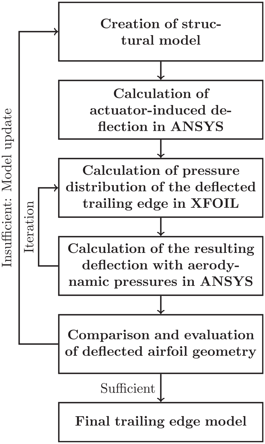
Process of trailing edge dimensioning.
A parameterized finite element model has been set up for the design process, where the airfoil data and all spanwise and chordwise coordinates of the trailing edge elements and the driving mechanism can be chosen. It is based on layered shell elements for the glass fiber structures and beam elements for the driving mechanism. Figure 6 shows the finite element model mesh with the colors according to the sections with different fiber ply stack.
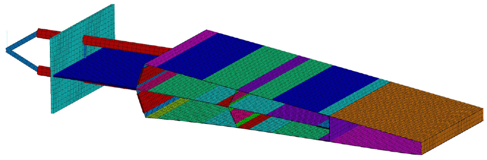
Finite element model of concept demonstrator.
Although the flow around a wind rotor blade cannot be fully described, a viscid XFOIL calculation is used for obtaining the pressure distributions with low calculation times based on the deformed airfoil shapes. This means, that the loads will be higher than in reality due to the 2D calculation in XFOIL.
With the chosen stiffness of the trailing edge, it could be obtained that a maximum of two iterations of the structural-aerodynamic analysis was necessary to reduce the difference in deflection between follow up iterations below
Demonstrator fabrication and lab test
Since its feasibility has been proven in multiple other morphing applications at DLR, HexPly 913 glass fiber prepreg material is used for the trailing edge. After finishing the design process, a fiber stacking was created and the coordinates were transferred from the finite element model to a CAD model. An image of the finished CAD model is presented in Figure 7. Since the fiber composite part shows multiple enclosed spaces, two possible ways exist for the fabrication. Either it can be made in one shot with silicone cores in the enclosed spaces, or the different parts are cured individually and joined afterward using adhesives. Due to the prototype character, the differential approach has been chosen since the mold effort is much smaller and no cores are necessary.
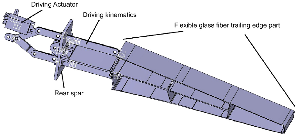
CAD model of concept demonstrator.
As driving actuator, aircraft model servo motors (Hitec HSB9380) are used. They are sufficiently strong and easy to implement and have a very small size. A photographic superposition of the neutral position and the maximum positive and negative deflection of the finished concept demonstrator is shown in Figure 8. With the settings of the driving motors a maximum deflection of
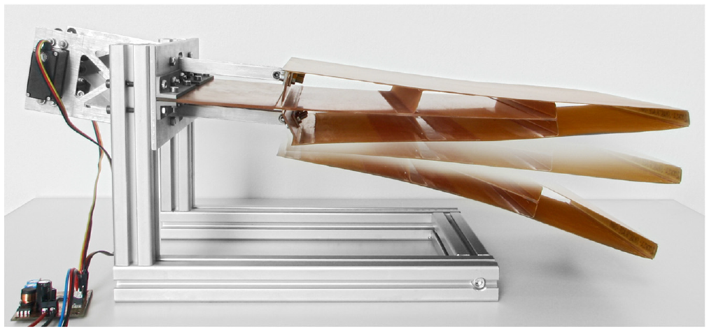
Trailing edge concept demonstrator.
To compare the simulated results from the finite element model, a comparison of the calculated and measured deflection is shown in Figure 9. The black lines represent the simulated shape whereas the gray points outline the measured airfoil. It can be seen that both data are nearly identical. Some deviations can be seen in the region of the second stringer and in the rear part, where the curvature of the simulation is slightly smaller than the measured results. This may happen due to stochastic deviations in the fabrication of the part.
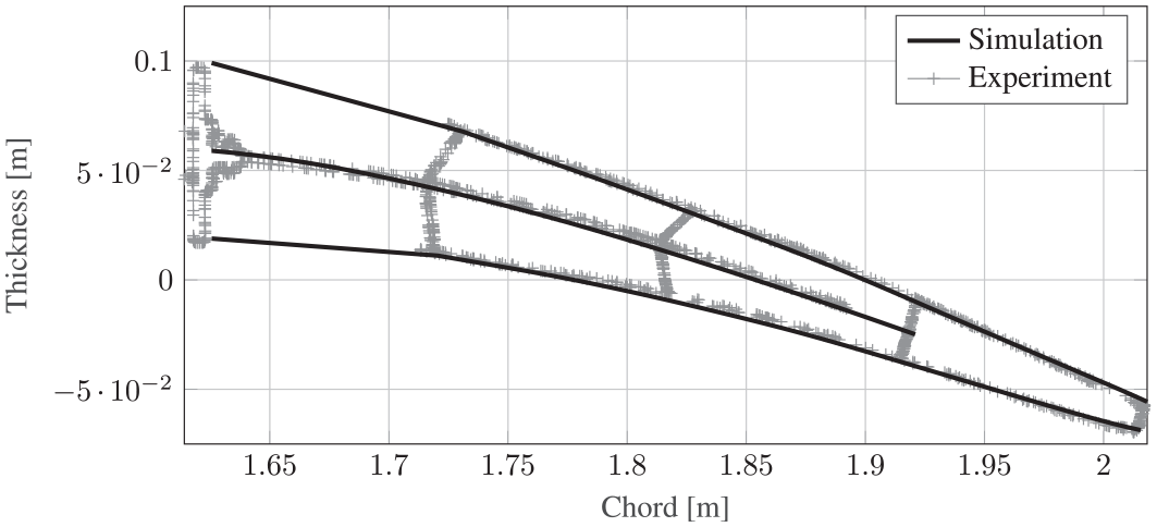
Simulated and experimentally obtained deflection pattern of concept demonstrator for a trailing edge angle of 10°.
In general, the validity of the simulation model is sufficient to use it for further design considerations of the flexible trailing edge.
Lessons learned from concept demonstrator
One crucial part has been left out in the design considerations in the previous chapters: The concept of the interconnection between the driving mechanism and the trailing edge, where the forces of the two beams of the driving mechanism are transferred to the glass fiber structure. For the concept demonstrator, the design shown in Figure 10 has been used. The basic idea is to use the first stringer of the fiber composite part of the trailing edge to attach a bracket with a joint for the beam of the driving mechanism. To spread the point forces of the driving mechanism along the span of the trailing edge, the central part f the stringer was reinforced with additional thickness. At the ends of the stringer toward the skin and the central spine, the material thickness of the fiber laminate was chosen thinner to allow a solid body joint.
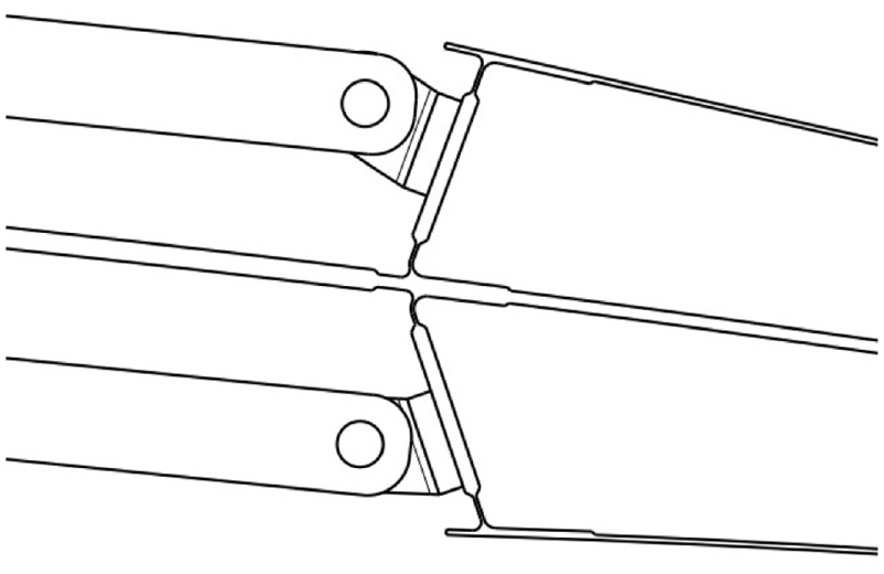
Driving mechanism attachment to composite trailing edge part for the concept demonstrator.
The advantage of this solution is the rather simple implementation in combination with the low height, which is needed in the thickness direction of the airfoil. Its main disadvantage arises from the fact, that the composite of the stringer is loaded in the out of plane direction and hence the solid body joints also have to bear shear forces. This limits their maximum length and thus increases the bending strains. To further investigate that, a finite element calculation was made for this structure as shown in Figure 11.
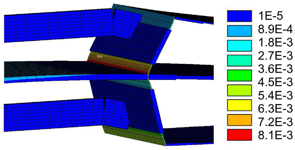
First principal strain of first pair of stringers at trailing edge.
There the first principal strain of the stringer part is displayed with no external aerodynamic loads. As expected, the maximum strain occurs in the solid body joint toward the central spine. With less than 1%, this is still in a region, where the prepreg material has proven to be functional for morphing applications as for example shown in Kintscher et al. (2016). For a test of the trailing edge concept, this is acceptable, but considering larger spans and extreme aerodynamic loads, either a great number of driving mechanisms is needed or otherwise the loads will be too high to introduce the driving force perpendicularly to the first stringer.
So for a practical implementation with higher span and fluctuating aerodynamic loading, a new concept of attaching the driving beams to the trailing edge composite part is needed in order to keep the strain ideally at a lower level well below 1%. Therefore, two main design changes are suggested:
Transfer the driving forces directly tangential to the skin instead of perpendicular to the stringer.
Stiffening of the front part of the fiber composite skin to spread the point forces of the driving mechanism along the span of the trailing edge.
The proposed solution for this issue consists in the inversion of the stiff and flexible part of the first stringer. By moving the stiff part to the skin of the trailing edge and the central spine, the required strain used by the solid body joint in the first stringer can be spread over a greater length. In addition, more cross section is available for the skin stiffener, which greatly improves the stiffness. Figure 12 shows the improved beam attachment. Comparing Figures 10 –12 it is clearly visible, that the length of the flexible part of the stringers is doubled and that the cross section of the stiffener at the upper and lower skin is much higher.
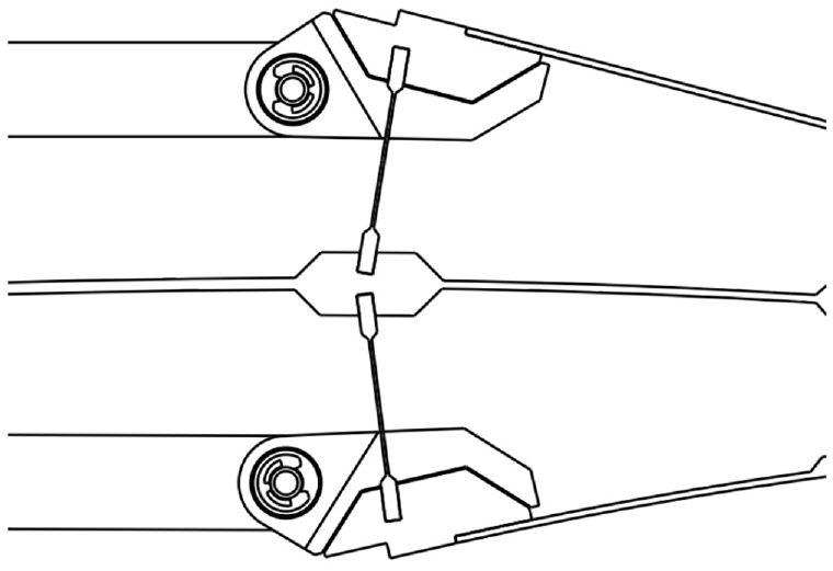
New design of the driving mechanism attachment to composite trailing edge part.
Besides the geometry of the stiffener and the stringer, the great advantage of this design is that it does not require forces perpendicular to fiber composite planes. Chordwise driving forces are introduced tangentially to the outer skin layers. Flapwise forces are acting longitudinally to the stringer. Therefore, bending forces within the fiber panels are kept at a minimum. Based on this concept, the segment demonstrator will be designed for the rotating test.
Segment demonstrator for rotational and wind tunnel testing
Scientific goals and design targets
After the concept demonstrator has proven the ability of the trailing edge to deform, the next step is to test the concept in a more realistic environment than a laboratory room. The ideal way therefore would be to implement the trailing edge in a real wind turbine. Since this requires a much larger trailing edge with twist and taper as well as building a modified set of rotor blades which are adapted to host a flexible trailing edge, the effort and risk of such a project would be very high. Therefore, an intermediate step is helpful.
This can be found in the rotating test rig at DTU in Risø, which has already been mentioned in the literature chapter. This rotating rest rig has been set up from an old
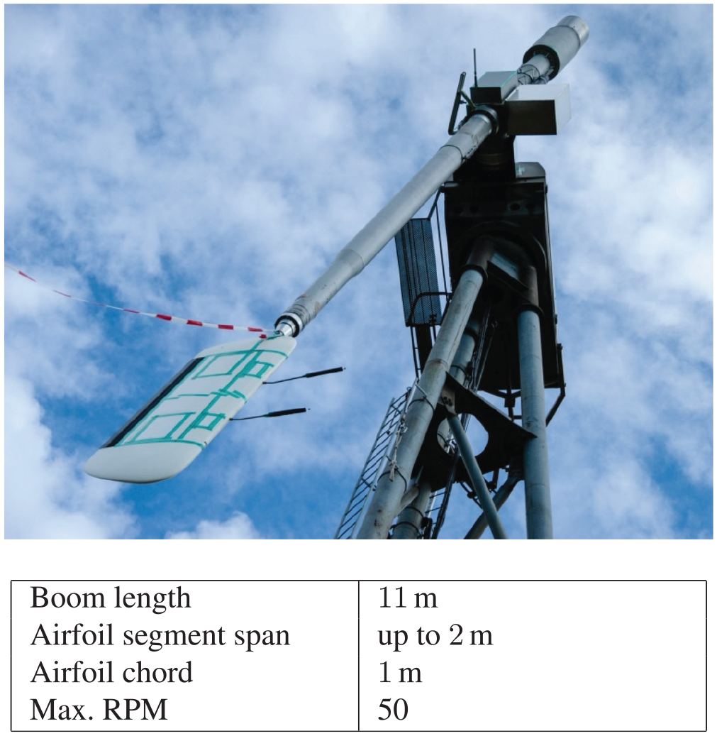
Photo of DTU rotating test rig and technical data (Image and data from Barlas and Aagaard Madsen, 2014).
With this test rig, experiments in real wind conditions with a rotating flow are possible. Due to the limited size, a constant cross section of the airfoil and no need for modified blades, the effort for such an experiment can be significantly smaller. In Barlas and Aagaard Madsen (2014) the design process and the characteristics of the rotating test rig are explained.
Aiming for tests with this test rig, a segment demonstrator using the previously shown trailing edge concept is designed and built. In the experiments, the following topics are targeted:
Demonstration of the trailing edge morphing in rotation with aerodynamic forces.
Measurement of flap polars for several flap positions in real wind conditions.
Compensation of boom bending moments using the trailing edge flap and different input signals.
In order to comply with the test rig requirements, the segment demonstrator of the flexible trailing edge will have a chord of
Structural design
Besides the changed design in the interface between the driving mechanism and the composite part of the trailing edge as shown at the end of the concept demonstrator chapter, the general design remains the same. The relative chord has been moved forward to 30% to increase the aerodynamic effect of the trailing edge as well as the vertical space for the driving mechanism. After dimensioning the trailing edge with the algorithm presented in Figure 5, a CAD model of the trailing edge is created, which can be seen in Figure 14.
Cross section of the flexible trailing edge.
Based on this CAD model, the trailing edge has been built. Comparably to the concept demonstrator, all fiber parts were individually fabricated (skins, central spine, and interconnecting stringers) and then glued together using epoxy adhesive to minimize mold effort and the necessity of silicone cores. Two photographs of the finalized trailing edge can be seen in Figure 15.
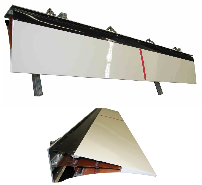
Flexible trailing edge for rotation test at DTU.
Additionally, the front part of the segment demonstrator incorporating leading edge, main spar and a rear wing box with a rear spar used to host the trailing edge was designed and built by DTU. This rear spar is shown at the left side of Figure 14 and is used as attachment point of the morphing trailing edge as well as the driving mechanism.
Laboratory testing the segment demonstrator
To check the applicability of the trailing edge for the planned test campaign and to validate the used finite element models, the movement of the trailing edge is measured in the laboratory. For these investigations, the outside shape of the trailing edge is obtained using a stereo camera system. Additionally, the strain on the central spine is measured with strain gages.
Figure 16 shows a superposition of the measured undeflected outside shape of the trailing edge together with the simulated and measured shape at
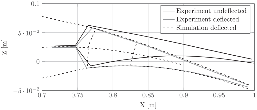
Simulated and experimentally obtained deflection pattern of segment demonstrator for a trailing edge angle of 10°.
To further quantify the accuracy of the finite element model, Figure 17 shows the trailing edge angle for different positions of the driving servo motors. Around the neutral position of the servo motor, both curves agree well. Especially at high positive deflections, the simulation predicts a higher deflection than the experiment. This can be expected since in the simulation the servo motor position is fixed relative to the rear spar, where the trailing edge is mounted. In the experiment, a comparable sheet metal construction as shown in Figure 8 is used to hold the servo motors. Due to the inherent flexibility of this servo motor fixture, its stiffness is lower in the experiment than in the simulation. For this reason, the achievable deflection of the trailing edge is lower in the experiment. With a deflection angle of
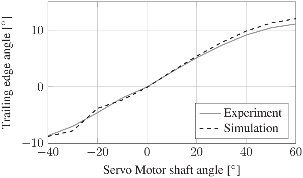
Comparison of simulated and measured trailing edge deflection angle.
As mentioned for the interface between the driving mechanism and the fiber parts of the trailing edge, keeping the strain in the glass fiber material at a minimum is the basis for a sufficient fatigue tolerance of the part. Therefore, the strain was measured to compare the results with the simulation. Figure 18 shows the chordwise strain distribution of the upper side of the trailing edge in chordwise direction for the fully positive deflection of the trailing edge. In the experiment, the strain gages are only applied on the central spine between the reinforcements, where the stringers are attached to the central spine. Therefore the curve in Figure 18 shows two gaps at
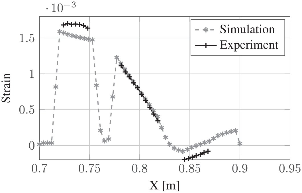
Simulated and measured strain pattern of middle spine for full positive deflection.
Comparing the simulated and measured strain, it is obvious, that the measured strain is higher than the simulated strain the forward section of the flexible trailing edge. Toward the trailing edge, the experiment shows a lower strain and in the middle section, the strain agrees well in simulation and experiment. The most probable explanation for these deviations is supposed to be an underestimated stiffness of the outer skins, which leads to a higher deformation in the forward part of the trailing edge and a reduced deformation in the rear part.
In Figure 19, the simulated and measured strains at a chord position of
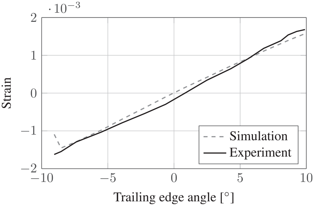
Simulated and measured strain at
Conclusion and outlook
As mentioned in the introduction, reducing the loads on wind turbine blades is one way to allow further increase of the size of rotors, which then leads to a higher energy yield of the individual turbine. Therefore, a design of a flexible trailing edge has been derived and presented in this paper, which allows to change the lift in the outer part of the blade. Subsequently, this change in lift can be used to control bending moments in the blade root section.
For the design, a coupled structural and aerodynamic analysis algorithm has been set up around a finite element model in ANSYS, where aerodynamic loads are calculated using XFOIL. Based on these considerations, a concept demonstrator was built and measured. Since the simulated and the measured deflection agree well, the finite element model of the trailing edge is sufficiently precise.
With this model, the segment demonstrator was designed with a span of
The experimental investigation of the segment demonstrator at the rotating test rig and in the wind tunnel have been performed in 2018 and 2019. Their results will be presented in a separate paper.
Footnotes
Declaration of conflicting interests
The author(s) declared no potential conflicts of interest with respect to the research, authorship, and/or publication of this article.
Funding
The author(s) disclosed receipt of the following financial support for the research, authorship, and/or publication of this article: This work was funded by the Federal Ministry for Economic Affairs and Climate Action on decision of the German Bundestag in the frame of the SmartBlades project (funding reference no. 0325601A/B/C/D).