
Abstract
Background:
A low-cost, yet high-functioning, fabrication method for prosthetic components is needed to provide underserved amputee communities with quality mobility devices. Three-dimensional printing is a potential alternative, yet limitations in material characteristics have previously prevented the technology from emerging as a solution.
Objective:
To validate the application of a novel three-dimensional printing technique as a fabrication method for creating fiber composite patient end-use prosthetic feet.
Study design:
Experimental designs were iterated upon throughout mechanical testing.
Methods:
A testing apparatus capable of loading prosthetic feet in dorsiflexion and plantarflexion was constructed. Load displacement data were gathered, and energy analyses were conducted. The three-dimensionally printed feet were compared to a Freedom Innovations Renegade® MX carbon fiber foot and a solid-ankle cushion heel foot.
Results:
The three-dimensionally printed feet achieved energy profiles that were similar, and in some cases preferable, to the energy profiles of the Renegade MX and solid-ankle cushion heel foot. The stiffness profiles of the three-dimensionally printed feet varied widely and depended greatly on the design of the feet, as well as the amount and location of the fiber reinforcement.
Conclusion:
Composite filament fabrication three-dimensional printing has the potential to serve as a fabrication method for the production of energy returning prosthetic feet.
Clinical relevance:
The results of this study indicate that carbon fiber reinforced three-dimensionally printed prosthetic feet have the potential to serve as a low-cost alternative to carbon fiber prosthetic feet and that three-dimensional printing has the capacity to function as a viable fabrication method for patient end-use prosthetic components.
Keywords
Background
According to estimates by the Amputee Coalition and the Centers for Disease Control and Prevention (CDC), in the United States, there are 185,000 upper and lower limb amputations that occur annually, and the number of Americans living with an amputation is projected to reach 3.6 million by the year 2050. 1 These statistics are reflected in the global context, yet access to prosthetic care and technology varies drastically—according to the World Health Organization, only 1 in 10 persons located in low-resource areas has access to adequate prosthetic technology. 2 The standard prosthetic foot for amputees in low-resource areas is the solid-ankle cushion heel (SACH) foot, a low-cost option that provides low amounts of energy storage and return during gait. 3 The most important factors in the design of a prosthetic foot are the ability to store energy gathered during early phases of gait, and to return that energy to the amputee during later phases (a dynamic elastic response), 4 thereby assisting in gait by demanding less energy input from the user.
The SACH foot compares poorly to current high-performance prosthetic feet, which are typically fabricated using a high-density carbon fiber reinforced composite that is expensive to produce, which thereby drives up cost to the patient. 5 However, new additive manufacturing techniques provide possible solutions to the issues of cost and distribution associated with high-performance carbon fiber composite prosthetic feet.
The purpose of this study is to address the viability of three-dimensional (3D) printed prosthetic feet fabricated with fiber-reinforced materials. It was hypothesized that such feet could achieve similar dynamic functions to those of industry standard carbon fiber prosthetic feet. Limitations in traditional additive manufacturing fabrication techniques have thus far caused 3D printing to be discounted as a viable fabrication method for high-performance prosthetic devices, although 3D printing has been utilized for lower limb prosthetic fairings, lower limb sockets, and upper limb prostheses.6–11 3D printing has been recognized as a high potential technology, and a possible cost-effective fabrication technique for delivery of prosthetic components. 12 Advancements in 3D printing techniques and materials suggest the capacity for the technology to fill the need for financially obtainable, energy returning prosthetic components.
Methods
The American Orthotic & Prosthetic Association (AOPA) Prosthetic Foot Project was referenced as a template procedure to obtain energy and stiffness data from two predicate feet and seven 3D printed feet reinforced with continuous carbon fiber filament. 13 Industry standard metrics of percent energy return and compressive loading were used to assess the viability of each foot design. Iterations were informed by mechanical testing, and deficiencies were addressed to create optimally dynamic designs.
This study involved purely mechanical testing of various prosthetic feet, and as such, no ethical permission was required.
Foot design
The functional design characteristics of conventional prosthetic feet, such as the Freedom Innovations Renegade® MX, informed the fiber reinforcement routing patterns incorporated in the 3D printed feet. In order to ensure that force applied during the gait cycle would occur parallel to the direction of the fibers, reinforcements were fabricated in concentric rings by orienting the medial side of the feet down on the print platform. This orientation was chosen to maximize flexibility and ensure a dynamic elastic response during testing. Feet 1–7 were designed and 3D printed and are shown in Figure 1. The dark-colored regions of the 3D printed feet are composed of nylon reinforced with carbon fiber filament fabricated in the aforementioned concentric rings, while the lighter areas of the feet are pure nylon (I). The fiber routing pattern for each foot is also shown as it appears in the 3D printing software (II).
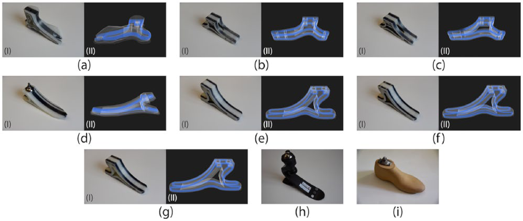
(a) Foot 1, (b) Foot 2, (c) Foot 3, (d) Foot 4, (e) Foot 5, (f) Foot 6, (g) Foot 7, (h) Freedom Innovations Renegade® MX, and (i) SACH foot.
Foot 1 was designed with three concentric carbon fiber rings, a number chosen to keep the cost of the foot low, and to provide a structural baseline to iterate further upon. In Foot 1, an initial band of carbon fiber was incorporated to prevent warping in the printing process. A similar fiber band can also be seen in Foot 4, but as a result of the placement of the fibers closer to the medial and lateral extremes in subsequent designs, similar bands were not included. While Feet 1 and 3 incorporated three continuous concentric fiber rings in one band, all other 3D printed feet incorporated four rings in two bands in order to assure structural integrity. Foot 2 shifted to a more functional form and was shortened to decrease build time and material use. Aiming to increase flexibility and improve the overall dynamic response, the inner core of the foot was left open to create four fiber beams. Foot 3 incrementally improved upon the design of Foot 2 by adjusting the shape of the four beams and creating a larger opening in the inner core. The arch of the foot was lowered in an attempt to increase flexibility, and the shape of the toe was adjusted to reduce the amount of fiber required for fabrication. In Foot 4, the larger inner cutout was removed in favor of increased surface area, the profile of the toe was lengthened, and the fiber routing was adjusted to create a single large band. The narrow shape and lengthened toe were adopted to attempt to create a larger bending moment in the foot. Foot 5 maintained the flat surface profile of Foot 4, but incorporated additional heel height to increase flexibility. To increase lateral stability while maintaining adequate dynamic response, the fiber routing pattern was adjusted to create two independent bands similar to Foot 3. Feet 6 and 7 incorporated incremental changes to the Foot 5 design, whereby the profiles of the feet were adjusted, and minor changes in the thickness of the toe and heel sections were introduced. Each experimental foot contained retaining features for stainless steel nuts and bolts, which were used to secure a conventional pyramid adapter on the top surface of each foot, thereby enabling the feet to be mounted to the testing apparatus.
Foot fabrication
The experimental, carbon fiber composite feet were fabricated using a Mark Two composite filament fabrication (CFF) 3D printer (Markforged, Inc., Watertown, MA) capable of fabricating nylon reinforced with embedded continuous fiber strands. The resultant fiber composite rivals the characteristics of similar composite materials. 14 The fiber routing for each foot was programmed using Eiger, a slicing software produced by Markforged, Inc. that enables computer-generated models to be printed on a Mark Two printer. Using Eiger, the location, orientation, and amount of carbon fiber in each foot were specified.
Each foot was printed with a layer height of 0.125 mm, a triangular infill support pattern (geometric shape repeated on the interior of a part to add structural support), and fill densities (density of a part’s internal structure) ranging from 20% to 50%. A summary of the material characteristics for each 3D printed foot can be found in Table 1.
Summary of material usage, cost, weight, carbon fiber composite volume fraction, number of concentric fiber rings, and nylon fill density of each 3D printed foot.
SACH: solid-ankle cushion heel; N/A: not applicable.
The raw material cost of the nylon filament used was US$0.21/cm3. The raw material cost of the carbon fiber filament used was US$1.50/cm3. As raw material costs could not be obtained for the predicate feet, clinical price estimates for the Renegade® MX and SACH were provided by Sampson’s Prosthetic and Orthotic Laboratory, Schenectady, NY. All other data on the predicate feet were either not relevant or could not be obtained from the specific manufacturing companies.
Data collection
Predicate device selection
A 28 cm Freedom Innovations Renegade MX dynamic carbon fiber prosthetic foot, and a K10, size medium, SACH foot were used as predicate devices. The Renegade MX is classified as a dynamic response, K3 energy returning foot, and is rated to a user weight of 130 kg (285 lbs). 15 The Renegade MX is similar in form to the seven 3D printed feet and is classified as a high-activity level dynamic energy returning foot (a classification the seven 3D printed feet were designed to attempt to meet). A foot manufactured by Freedom Innovations was preferred, as the company has used the same AOPA Prosthetic Foot Project to measure dynamic energy response in similar carbon fiber composite prosthetic feet.16–18 A SACH foot is the simplest form of a non-articulated foot and was chosen because of its wide use in global clinical settings. 19
Procedure
Data collection was performed using an Instron 1321 servohydraulic materials testing machine (Instron Corporation, Norwood, MA). The data collection procedure was based on testing guidelines recommended by the AOPA Prosthetic Foot Project 13 and provided an easily repeatable means of comparing mechanical characteristics of the experimental feet in two modes of loaded flexion (plantarflexion and dorsiflexion). In accordance with the AOPA recommendations, each prosthetic foot was attached to the Instron machine via an embedded prosthetic pylon, a tube clamp with standard female pyramid adapter, a standard male pyramid adapter, and alignment set screws. Once attached to the pylon, the foot was initially positioned above a plate inclined to 20° and set in a neutral alignment position. The test setup can be seen in Figure 2.
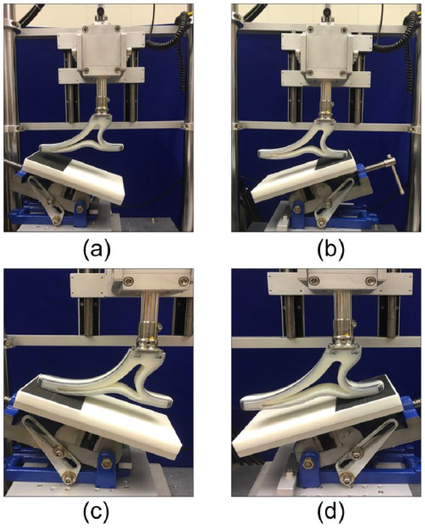
(a) A foot positioned in the testing rig for a dorsiflexion test before loading. (b) A foot positioned in the testing rig for a plantarflexion test before loading. (c) A foot forced into dorsiflexion during loading. (d) A foot forced into plantarflexion during loading.
Each foot was initially positioned for forced flexion in either dorsiflexion (Figure 2(a)) or plantarflexion (Figure 2(b)), and in order to assist in tightening the set screws on the pyramid adapter, loaded to 50 N. Displacement was zeroed at 50 N, and the feet were then loaded to 1230 N and returned to 50 N at a rate of 200 N/s. The 1230 N load forced the feet into contact with the plate, resulting in approximately 20° of flexion in either dorsiflexion (Figure 2(c)) or plantarflexion (Figure 2(d)). The loading value of 1230 N was identified by the AOPA Prosthetic Foot Project as representative of an average patient applying weight to the tested device during gait. This loading pattern was repeated twice consecutively, and load and displacement were recorded at a sampling rate of 25 Hz during both loading cycles.
Data processing and analysis
Load–displacement data gathered from each plantarflexion and dorsiflexion loading cycle were translated into load–displacement curves. The aggregated hysteresis data gathered from each foot in both plantarflexion and dorsiflexion loading were combined in two representative graphs (Figure 3(a) and (b)). These graphs represent the load–displacement patterns of each foot in the plantarflexion and dorsiflexion loading cycles and were used to calculate stiffness and energy data. The Freedom Innovations Renegade MX predicate prosthetic foot device is denoted “Renegade” and the SACH foot is indicated by “SACH.”

(a) Combined overall hysteresis data of dorsiflexion loading and unloading in all tested feet. (b) Combined overall hysteresis data of plantarflexion loading and unloading in all tested feet. (c) Sample dorsiflexion loading and unloading load–displacement curves isolated for stiffness and energy return calculations, taken from data collected from Foot 6. (d) Sample plantarflexion loading and unloading load–displacement curves isolated for stiffness and energy return calculations, taken from data collected from Foot 6.
For each foot, in accordance with the standard linear displacement offset method, stiffness (N/mm) was measured as the average slope of the linear portions of the corresponding plantarflexion and dorsiflexion loading curves (Figure 3(c) and (d)). 20 Polynomial coefficients of a first degree, least-squares best fit equation for the specified linear dataset were found and used to create a line from which the slopes were calculated. Total energy capacity (J) for each foot was calculated as the average area under each of the loading portions of the load–displacement curves. Energy return (J) for each foot was calculated as the average area under each of the unloading portions of the load–displacement curves. The energy and stiffness data gathered from the two loading cycles applied to each foot were averaged to obtain a representative final value. The areas under loading curves in Figure 3(c) and (d) used for energy calculations are not shaded in the sample isolated load–displacement graphs. The dashed lines represent the average slope of the linear portion of the loading graph from which stiffness calculations were derived, while the shaded areas under the unloading curves represent the areas from which energy return was calculated for each foot. Energy dissipation (J) in each foot was calculated as the difference between total energy capacity and energy return. Area calculations were conducted using the trapezoidal integration method. 13
Results
A summary of the specific stiffness and energy values of each foot is presented in Table 2. The 3D printed feet fell within the range of 10–40 mm (mean, 31.8 mm) of displacement in dorsiflexion and 5–15 mm (mean, 9.7 mm) in plantarflexion. However, Foot 4 fractured in dorsiflexion loading and produced outlier data that were excluded from further analysis. Most likely due to the higher density of carbon fiber, the Renegade MX foot experienced 52.0 mm of displacement in dorsiflexion and 39.1 mm in plantarflexion. The SACH foot experienced 18.3 mm of displacement in dorsiflexion and 49.9 mm in plantarflexion. Due to the construction of the soft cushioned heel, the SACH foot did not flex in plantarflexion during loading as the other feet had, instead exhibiting high levels of linear heel compression.
Summary of energy and stiffness data.
SACH: solid-ankle cushion heel.
A summary of the total energy capacity, energy return, and energy dissipation in each foot can be found in Figure 4. Total energy represents the energy incurred during loading, returned energy represents the energy returned during unloading, and dissipated energy represents the difference between the loading and unloading energy values. Although the average total energy capacity of the 3D printed feet (5.3 ± 2.4 J in plantarflexion, 18.6 ± 4.9 J in dorsiflexion) was smaller than the energy capacity of the Renegade MX (10.8 J in plantarflexion, 25.7 J in dorsiflexion), the standard deviation indicates a wide range of results. The average total energy capacity of the 3D printed feet was higher than the SACH foot in dorsiflexion (6.7 J), yet lower than the SACH foot in plantarflexion (20.7 J).
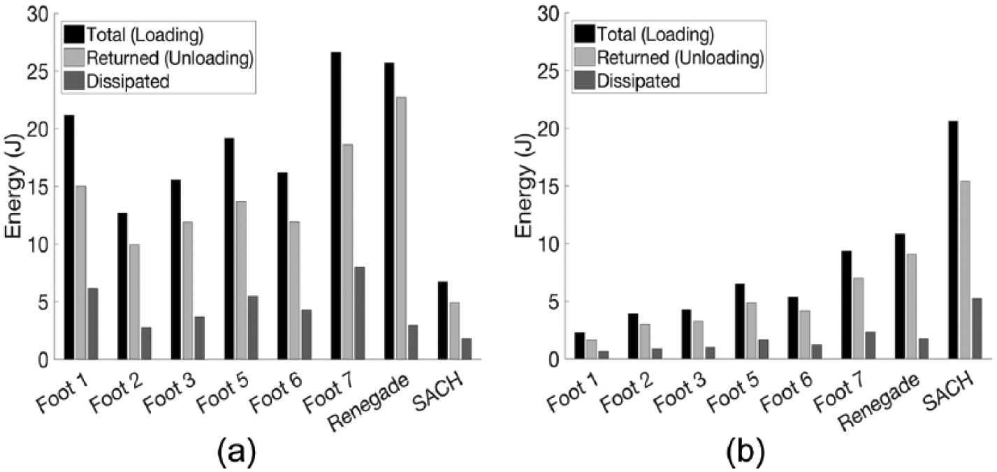
(a) Energy behavior of the feet tested in dorsiflexion. (b) Energy behavior of the feet tested in plantarflexion.
The stiffness values of each foot, as well as the percentages of energy returned, can be found in Figure 5. Percent energy return was found by calculating the ratio of total energy capacity to returned energy of each foot. The average stiffness of the 3D printed feet was higher in plantarflexion than in dorsiflexion (174.2 ± 88.3 N/mm in plantarflexion, 44.2 ± 12.1 N/mm in dorsiflexion), but both measures showed wide variation. However, the average percent energy returned for the 3D printed feet in both plantarflexion and dorsiflexion (75.7% ± 1.9% in plantarflexion, 73.7% ± 3.3% in dorsiflexion) were comparable in magnitude to the energy return values of the Renegade MX (83.9% in plantarflexion, 88.8% in dorsiflexion) and the SACH (75.4% in plantarflexion, 74.0% in dorsiflexion).
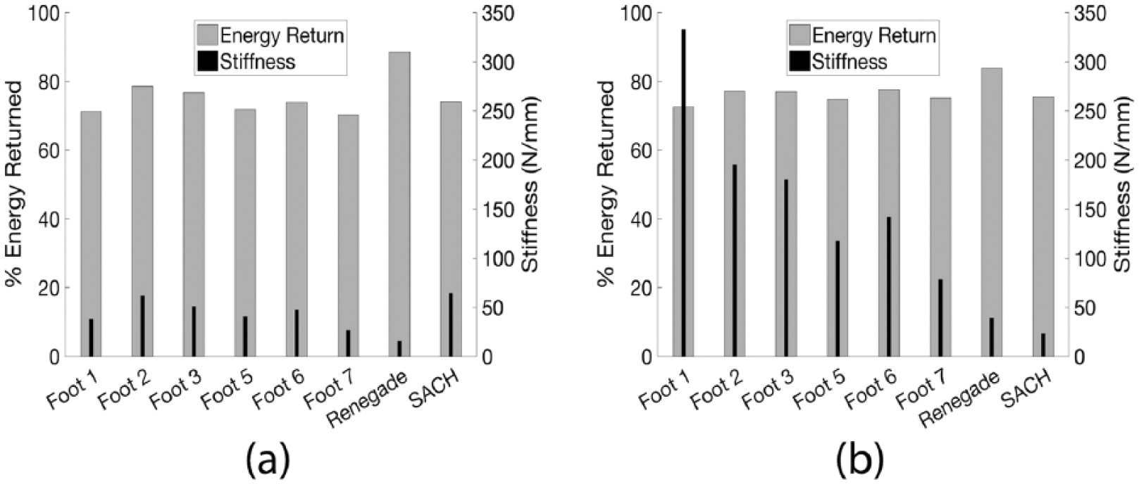
(a) Percent energy returned compared with stiffness in dorsiflexion loading. (b) Percent energy returned compared with stiffness in plantarflexion loading.
Discussion
The goal of this analysis was to examine whether CFF 3D printing fabrication techniques can produce devices with energy return values that are similar to commercially available prosthetic feet. Energy return reflects the amount of propulsive force an amputee receives during gait—higher values correspond to higher levels of assistance and can aid an amputee in achieving a normal gait pattern. 5 From criteria established by the AOPA Prosthetic Foot Project, 13 an energy returning foot exhibits a displacement of at least 25 mm and an energy return of at least 75% at 1230 N of load in dorsiflexion, and a displacement of at least 13 mm and an energy return of at least 82% at 1230 N of load in plantarflexion. While none of the 3D printed prosthetic feet met both of these dynamic criteria, some gave adequate results in either plantarflexion or dorsiflexion. Foot 3 passed the dynamic test in dorsiflexion (exhibiting 76.8% energy return and 26.2 mm of displacement), and Foot 7 passed the dynamic test in plantarflexion displacement (exhibiting 16.9 mm of displacement).
A possible cause of the difference in energy performance is overall composite material stiffness of the feet. While an inverse relationship between stiffness and percent energy return for the 3D printed prosthetic feet was observed, this did not hold true for the Renegade MX. Generally, the stiffer 3D printed feet yielded more energy return, yet the Renegade MX was the least stiff overall and exhibited the most percent energy return. This discrepancy is most likely caused by the composition of the Renegade MX. High volume fraction carbon fiber composites are typically used in prosthetic foot fabrication, rather than the carbon fiber and nylon composite blend of lower volume fraction that was created by the CFF 3D printing process. 21
In an attempt to achieve the high flexibility of the Renegade MX, relevant features were introduced in the design evolutions of the 3D printed feet. Although these design evolutions provided decreased energy return with decreased stiffness, the total energy gained increased with decreased stiffness. While more energy was returned during the unloading stage of each foot, more energy was dissipated, resulting in a lower overall percent energy return.
Contrary to initial predictions, the SACH foot possessed the highest tested energy capacity in dorsiflexion. These outlier data are most likely a result of the construction of the SACH foot and the methods in which it was tested. The heel of the SACH foot compressed vertically in the plantarflexion test and did not flex in the same mechanism as the other feet. Because it performed in such a drastically different manner, the high total energy capacity relative to the 3D printed prosthetic feet was considered insignificant to the data interpretation.
Comparing the displacement values of the SACH foot and the 3D printed feet, the SACH foot had the least displacement of the tested feet in dorsiflexion, but had the most displacement in plantarflexion, most likely due to the construction of the cushioned heel. Feet 2, 3, and 6 exhibited less displacement than the SACH foot in plantarflexion, but exhibited more percent energy return. This result indicates that these specific designs could be viable options for a 3D printed prosthetic foot that is superior to a SACH foot in terms of energy return capabilities.
Considering the energy and displacement information gathered from the 3D printed feet, the data show that it is possible to 3D print prosthetic feet that possess some degree of energy storing and returning capabilities. To verify this possibility, further research could be conducted to test longevity through long-term cyclic loading, to test energy return variability using alternative fiber reinforcement materials or alternative fiber locations, and to tune the form, function, and patient suitability of the prosthetic components through engagement with clinical users. 22
Conclusion
While the average overall percent energy returns of the 3D printed feet were less than that of the Renegade MX, one of the 3D printed feet exceeded the 75% energy return and 25 mm displacement needed to be classified as dynamic in dorsiflexion, and many had total energy capacities that were similar, if not greater, than the predicate devices. The energy return results obtained for the CFF 3D printed prosthetic feet show that after further iterations and testing of the design and fabrication methods, feet constructed in this manner may be capable of consistently reaching a dynamic classification similar to that of an industry standard carbon fiber foot. Although the current 3D printed feet as a whole did not consistently achieve dynamic classification as defined by AOPA, 13 all of them exhibited some degree of energy return, suggesting that in the future, fiber-reinforced 3D printing has the potential to serve as a possible low-cost alternative for carbon fiber composite dynamic prosthetic foot fabrication.
Footnotes
Author contribution
H.H.W. fabricated feet, designed testing procedure, collected data, analyzed data, and prepared manuscript; J.K.F. conceptualized feet and prepared manuscript; J.C. conceptualized feet and prepared manuscript; R.R.G. fabricated testing apparatus, assisted with data collection; K.G. conceptualized research questions, assisted with data analysis and collection.
Declaration of conflicting interests
The author(s) declared no potential conflicts of interest with respect to the research, authorship, and/or publication of this article.
Funding
The author(s) received no financial support for the research, authorship, and/or publication of this article.