
Abstract
Background:
Limb movement between the residuum and socket continues to be an underlying factor in limb health, prosthetic comfort, and gait performance yet techniques to measure this have been underdeveloped.
Objectives:
Develop a method to measure motion between the residual limb and a transtibial prosthetic socket.
Study design:
Single subject, repeated measures with mathematical modeling.
Methods:
The gait of a participant with transtibial amputation was recorded using a motion capture system using a marker set that included arrays on the anterior distal tibia and the lateral epicondyle of the femur. The proximal or distal translation, anterior or posterior translation, and angular movements were quantified. A random Monte Carlo simulation based on the precision of the motion capture system and a model of the bone moving under the skin explored the technique’s accuracy. Residual limb tissue stiffness was modeled as a linear spring based on data from Papaioannou et al.
Results:
Residuum movement relative to the socket went through ~30 mm, 18 mm, and 15° range of motion. Root mean squared errors were 5.47 mm, 1.86 mm, and 0.75° when considering the modeled bone–skin movement in the proximal or distal, anterior or posterior, and angular directions, respectively.
Conclusion:
The measured movement was greater than the root mean squared error, indicating that this method can measure motion between the residuum and socket.
Clinical relevance
The ability to quantify movement between the residual limb and the prosthetic socket will improve prosthetic treatment through the evaluation of different prosthetic suspensions, socket designs, and motor control of the prosthetic interface.
Keywords
Background
The prosthetic socket is an important connection between the residuum and prosthesis. The relative movement between the residuum and socket that is allowed by current prosthetic technology continues to be an underlying factor in residuum limb health, prosthetic comfort, and gait performance.1,2 However, the techniques to quantify this motion have been underdeveloped.
Prior research specifically looking at motion between the residuum and the prosthesis during gait remains incomplete. 3 Most prior investigations were performed in a quasi-static environment using radiographic techniques that weight and unweight the limb.4–8 Dynamic tasks have also been explored using radiographic techniques during a step down and landing task 9 and in gait. 10 However, participants are exposed to radiation during this process, limiting the widespread use of these techniques.
Investigations of limb–socket motion during dynamic tasks where participants are not exposed to radiation have been accomplished during cycling11,12 and gait (albeit about one axis). 13 Sanders et al. 13 used a photoelectric sensor mounted distal to the limb to measure limb movement about the proximal or distal axis during gait. However, their work was confined to one axis and could not account for the interactive effect of a curved surface (e.g. residuum limb) moving in multiple planes. Childers et al. 11 expanded on the ideas proposed by Sanders et al. 13 and designed a device that could track the distal movement of the limb in two dimensions and applied it to a cycling task. Although the measurement resolution improved, the bulk of the device and the necessary socket modifications made it impractical. 11 A marker-based system was then developed which measured angular motion between the residuum and socket during a cycling task. 12 The expansion of the technique based on passive reflective markers to measure limb–socket movement from cycling to gait represents the next logical step in the development of this methodology.
This marker-based technique has two main clinical applications. First, it would provide a method to evaluate prosthetic socket fit and/or prosthetic suspension systems, and second, it could be used to find designs that control (and ideally minimize) limb–socket movement such as “pistoning” (i.e. the proximal or distal translation). Minimization of pistoning would also minimize the shear forces linked to the development of skin ulcers. 14 The technique could also be expanded to define motor control of the limb–socket interface by potentially relating muscle activation to the positioning of the residuum in the socket, affecting task mechanics. The ability to define how someone with a transtibial amputation controls his or her prosthesis is crucial to improving the rehabilitation technology and/or techniques that allow individuals to use their prosthesis for movement.
The purpose of this study was to (1) develop a method to measure relative motion in the sagittal plane between the residual limb and the prosthetic socket using passive retroreflective markers and an infrared-based motion capture system, (2) evaluate the effect of motion capture system accuracy, and (3) evaluate the potential confounding effect of the movement between the bone and skin by modeling the tissue as linear springs. The hypothesis tested was that the limb–socket movement measured with this method will be greater than the precision of the motion capture system and uncertainty due to bone–skin movement.
Methods
This study used a single subject in a repeated measures design combined with mathematical modeling to test a new technique to measure movement between the residuum and prosthetic socket. The measurement technique was tested using one male participant with a unilateral transtibial amputation secondary to trauma (74.8 kg, 1.8 m, 41 years, 10-year post-amputation). The participant was a K4-level ambulator who used a total surface bearing prosthetic socket with a size 26, 3-mm-thick silicone liner (Iceross, Össur, Reykjavik, Iceland), a pin-lock suspension (Air-lock; Coyote Design, Boise, ID, USA) with an energy storage and return-type prosthetic foot with vertical and transverse shock absorption (Rotate Reflex, Össur, Reykjavik, Iceland). The prosthetic socket was a duplicate of the participant’s socket (0-ply fit) and was modified by extending the proximal or lateral trimline and drilling a 40-mm-diameter hole at the location of the lateral epicondyle of the femur (LEF) and a 15-mm-diameter hole at the location of the anterior distal tibia (ADT). The participant’s alignment and foot were transferred from their existing prosthesis by a certified prosthetist. The study protocol and informed consent forms were approved by the institutional review board.
Three suspension conditions were tested: pin (Air-lock; Coyote Design), knee sleeve (Flexisleeve; Engineered Silicone Products, Newton, NJ, USA), and combined pin + knee sleeve. These suspensions were used to demonstrate the resolution of this technique as they hold the residuum to the prosthesis distally (pin), proximally (knee sleeve), and both distally and proximally (pin + knee sleeve) and should, therefore, alter the type of motions allowed at this interface.
Marker set development
This technique used retroreflective markers placed on the prosthetic socket and residual limb, an eight-infrared camera motion capture system (Vicon Motion Systems Ltd, Oxford, UK), and mathematical equations that defined the position and orientation of the residual limb segment relative to the prosthetic socket.
The Vicon PlugInGait lower body marker set (Vicon Motion Systems Ltd) was modified to include additional markers to track the movement of the residual limb segment (Figure 1). Marker bases were applied directly to the skin over the lateral LEF and ADT. The liner was then punctured to allow for marker bases to protrude through the liner and holes in the prosthetic socket. The holes in the liner were resealed with silicone. It is important to have the marker bases applied directly to the skin and through the liner because this allows the liner to help stabilize both limb tissues and marker locations relative to their intended position.
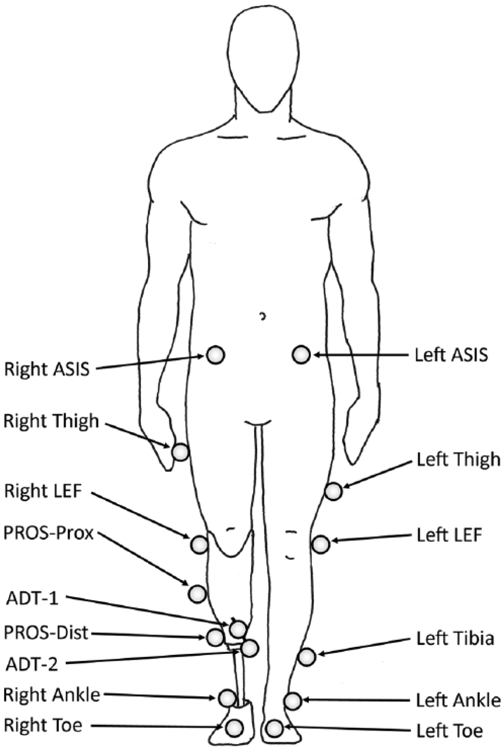
Overview of the marker set used was based on Vicon Plug-In-Gait with the addition of the marker array to locate the anterior distal tibia (ADT-1 and ADT-2) and an additional marker on the prosthesis (PROS-Dist). The marker PROS-Prox is synonymous with the right tibia marker normally associated with Plug-In-Gait. The four markers not shown are located bilaterally over the PSIS and the heel.
The ADT position required the use of a marker array with two markers (ADT-1 and ADT-2) to clear the relatively small hole in the prosthetic socket. Measurement error can be introduced if the surface of the liner moved relative to the baseplate on the skin, altering the angle of the array. This error was minimized using two markers on the array to form a line vector (Vector ADT) pointing back to the location of the baseplate, identified by a virtual marker on the skin over the ADT (Figure 2).
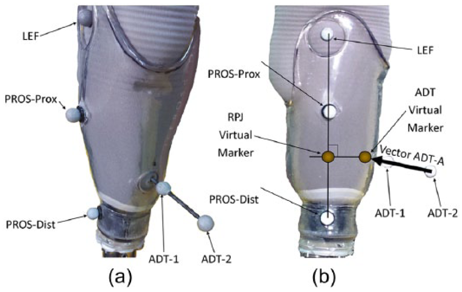
Marker identification along (a) oblique and (b) sagittal views. Markers were placed over the lateral epicondyle of the femur (LEF): two markers designated the centerline of the prosthetic socket (PROS-Prox and PROS-Dist) and two markers on an array (ADT-1 and ADT-2) that created vector ADT-A locating the virtual marker over anterior distal tibia (ADT). PROS-Prox and PROS-Dist markers designated the prosthetic limb segment. LEF and ADT designated the residual limb segment. A virtual marker at the residuum–prosthesis joint (RPJ) can then be located in reference to the prosthetic limb segment (RPJ-P) and located in reference to the residuum (RPJ-RL). Translation between RPJ-P and RPJ-RL defines how the residuum is translating relative to the prosthesis. In this figure, the RPJ-P and RPJ-RL lie on top of one another and are identified as the RPJ virtual marker.
The Vicon Plug-In-Gait marker set (Vicon Motion Systems Ltd) was modified to include the two markers on the marker array and two markers applied along the socket centerline on the lateral side (PROS-Prox and PROS-Dist). The prosthesis segment was defined by one marker distal to the marker on the LEF (PROS-Prox) and one marker located at the intersection of the locking pin with the prosthetic lock on the distal portion of the socket (PROS-Dist; Figure 2).
Data collection
The kinematic model was calibrated by having the participant stand quietly in the capture volume with equal weight on both limbs, which was verified by having each limb on a force platform (OR6, Advanced Mechanical Technology Inc., Watertown, MA, USA). This defined the neutral alignment of the residuum relative to the prosthesis. Marker positions were recorded at 100 Hz, and ground reaction forces were recorded at 1000 Hz using Vicon Nexus 1.8.4 (Vicon Motion Systems Ltd). The participant traversed the walkway at a self-selected pace until five successful trials (i.e. each foot struck the force platform) were collected. Three suspension conditions were tested: pin, knee sleeve, and combined pin + knee sleeve. A hole was cut into the knee sleeve to uncover the LEF and PROS-Prox markers.
Data analysis
The limb–socket movement in the sagittal plane was calculated about the residual limb–prosthesis pseudo-joint (RPJ). The RPJ point is located at the intersection of a line between PROS-Dist and LEF markers and a second line perpendicular to the first line and through the ADT virtual marker (Figure 2). This point was defined when the participant was standing during marker calibration. The RPJ point acts as a virtual marker relative to both the residual limb segment (RPJ-RL) and the prosthesis (RPJ-P). Segmental translation is then defined as relative movement between the RPJ-RL and RPJ-P virtual markers within the prosthesis coordinate system. Here, vertical displacement represents proximal or distal movement, and horizontal movement is perpendicular to the vertical direction (anterior or posterior direction). Angular movement is the angular difference between lines defined by the LEF and RPJ-RL markers for the residuum and PROS-Prox and RPJ-P markers for the prosthesis. The residuum’s instant center of rotation about the prosthesis was calculated by finding the intersection of lines perpendicular at the midpoint of the lines formed by LEF and ADT. 15
Segmental motion and joint moments were calculated using MATLAB 2013b (MathWorks, Natick, MA, USA) from recorded kinematics and ground reaction forces via inverse dynamics 16 at the ankle, the RPJ point (about point RPJ-P), knee, and hip. Mass and inertial properties of the intact limb segments were estimated from regression equations, 17 prosthetic properties were measured using a pendulum technique,18,19 and residual limb properties were estimated from mathematical models. 18
Random Monte Carlo simulation to investigate technique accuracy and precision
The motion capture system accuracy and precision in combination with a relatively short limb segment may affect the accuracy of this technique to assess movement. Therefore, a random Monte Carlo simulation 20 was constructed. This analysis technique begins by assigning a probabilistic distribution curve to the input parameters (maker location and the precision of the motion capture system) within a mathematical formula (constructing relative residuum–socket movement). Then, the calculation is repeated thousands of times with each sampling pulling from the input variable’s assigned pseudo-random distribution creating a bin full of outputs from the individual calculations. The mean and variability of all of the outputs then represents the accuracy and precision of the formula given the accuracy and precision of the inputs. Monte Carlo analyses are computationally expensive but consistently demonstrate an ability to converge about the correct solution. 20
One experimental trial (4, with pin suspension) was selected for the simulation because it contained the greatest range of motion of all 15 trials collected. A normal distribution curve was used for all simulation input variables with the mean set by the coordinate data from trial 4 and the standard deviation obtained experimentally (0.62 mm). The simulation was iterated 10,000 times at intervals of 10% throughout the gait cycle. The model outputs were angular, proximal or distal, and anterior or posterior movement mean and standard deviations for each gait cycle interval. The root mean squared error (RMSE) evaluated absolute differences between movement calculated with output from the motion capture system and the simulation to include uncertainty in the marker position. The precision of this marker set was defined as the mean standard deviation calculated about each gait cycle interval.
Simple bone–skin model to investigate the effect of bone–skin movement
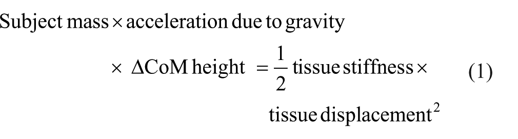
The movement of the amputated bone relative to the skin could influence the accuracy of this measurement technique. This effect was explored by modeling residual limb tissue around the ADT as a simple linear spring and using forces acting on the RPJ joint (calculated via inverse dynamics) to find the relative displacement between the cut end of the tibia and the marker baseplate. First, the stiffness of residual limb tissues was estimated using a study that quantified three-dimensional (3D) bone–tissue movement in 10 persons with a transtibial amputation, landing from a height of 22 cm. 9 Data presented on participant 4 (92.2 kg) demonstrated the greatest displacement between the skin and tibia (24.16 mm) and represented a worst-case scenario for this investigation. 9 Using conservation of energy equations (equation (1)) based on a subject mass (92.2 kg), the change in center of mass height (0.22 m drop height), acceleration due to gravity (9.81 m/s2), tissue displacement during that drop (0.025 m), and then solving for the spring constant returned the tissue stiffness of those residual limb tissues (~640,000 N/m). Biological tissue stiffness behaves in a nonlinear fashion, especially when subjected to rapid decelerations like the drop test in Papaioannou et al. 9 To account for this, the value for tissue stiffness was then scaled for gait to better approximate linear behavior around tissue displacements typical of gait. Equation (1) was used again, but this time to calculate the amount of tissue displacement that same individual would have during gait. The change in center of mass height was changed to 0.062 m (from trial 4), and the tissue displacement was calculated to be 0.0133 m during gait. The peak force acting to move the residuum about the proximal or distal axis during gait from these data was 741 N. Therefore, tissue stiffness calculated from the drop experiment in Papaioannou et al. 9 was approximated for gait and then was scaled to our participant using forces derived from experimental results in a value for residual limb stiffness of ~56,000 N/m (741 N/0.0133 m)
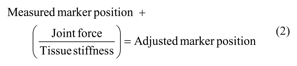
This stiffness was used to adjust the marker position at ADT and LEF in both the proximal or distal and anterior or posterior axes (equation (2)). The forces acting at the RPJ and knee joint were used for the forces acting at the ADT and LEF markers, respectively. The bone–skin movement in the vertical direction was offset by 6.9 mm due to the limb being loaded at 50% body weight during static calibration compared to being unweighted in the Papaioannou et al. 9 study. This adjusted the marker position based on where it would be relative to the actual joint center of the skeleton. Segmental movement was then recalculated for these adjusted marker positions to enable a comparison
Statistical analysis
A one-way analysis of variance (ANOVA) was used to evaluate the range of angular and translational movements during the entire stride between suspensions in the conditions tested (pin, knee sleeve, and pin + knee sleeve). If statistical significance occurred with the one-way ANOVA, a Tukey post hoc test was used to determine significance between suspension conditions.
Results
During the loading response phase of gait, the residuum was extended, located proximally and posteriorly inside the socket at initial contact, relative to its position during quiet standing, but quickly moved to a neutral position (Figure 3). The residuum in this general neutral position was similar to its alignment during the quiet standing calibration trial until the terminal stance or pre-swing phases of gait when it began to move anteriorly, proximally, and into flexion, with these movements peaking around the beginning of mid-swing (Figure 3). The residuum’s instant center of rotation about the prosthesis demonstrated some variability and averaged 23 mm posterior and 2 mm distal to the RPJ-Pros (Figure 4). The moment at the residuum–prosthesis joint demonstrated an extension moment from midstance through terminal contact with a peak during pre-swing (Figure 5).
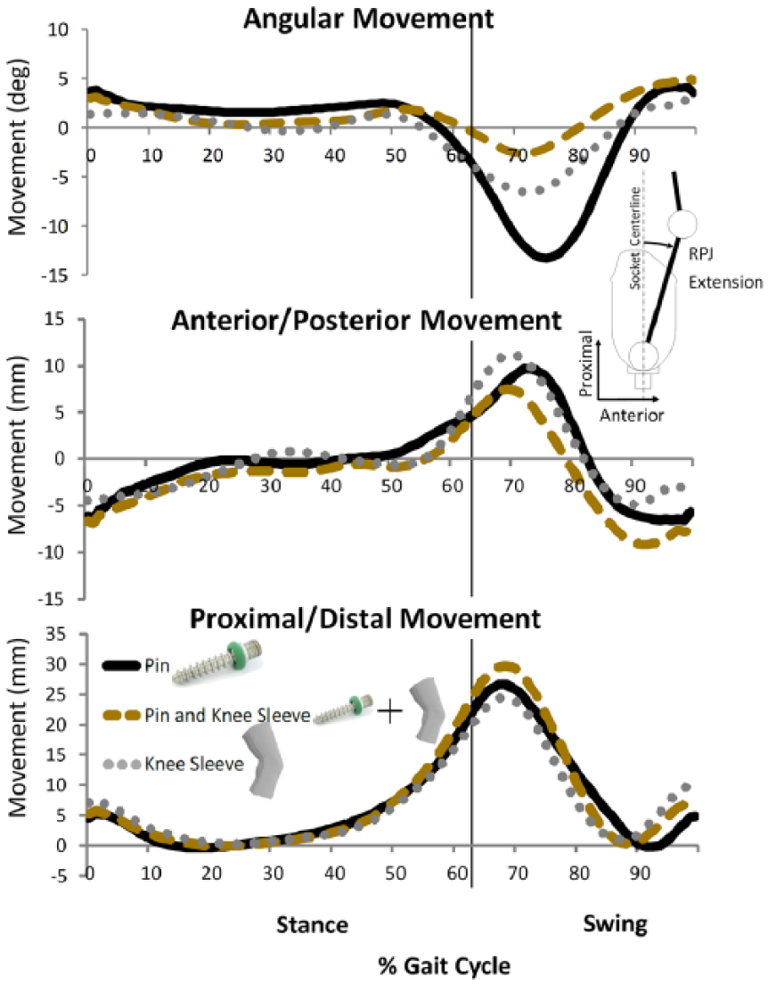
Movement between the residuum and prosthesis in the sagittal plane. The pin suspension (black line) demonstrated the greatest angular change compared to the knee sleeve (dotted line) and the combination of pin + knee sleeve (dashed line). Translational movement shown is between the residual limb segment (RPJ-RL) and prosthetic virtual marker (RPJ-P) and within the prosthesis coordinate system.
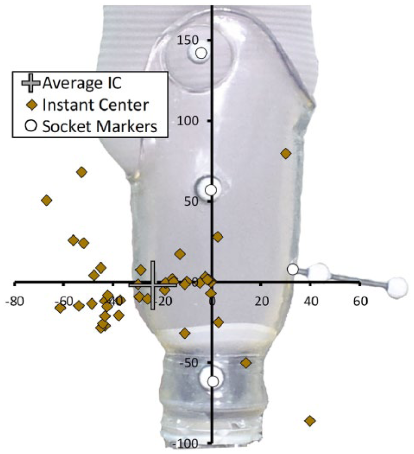
Instant center of rotation of residuum about the prosthesis at intervals of 3% of the gait cycle (diamonds). The average instant center for the entire gait cycle (plus sign) is located ~25 mm posterior to the RPJ joint (origin).
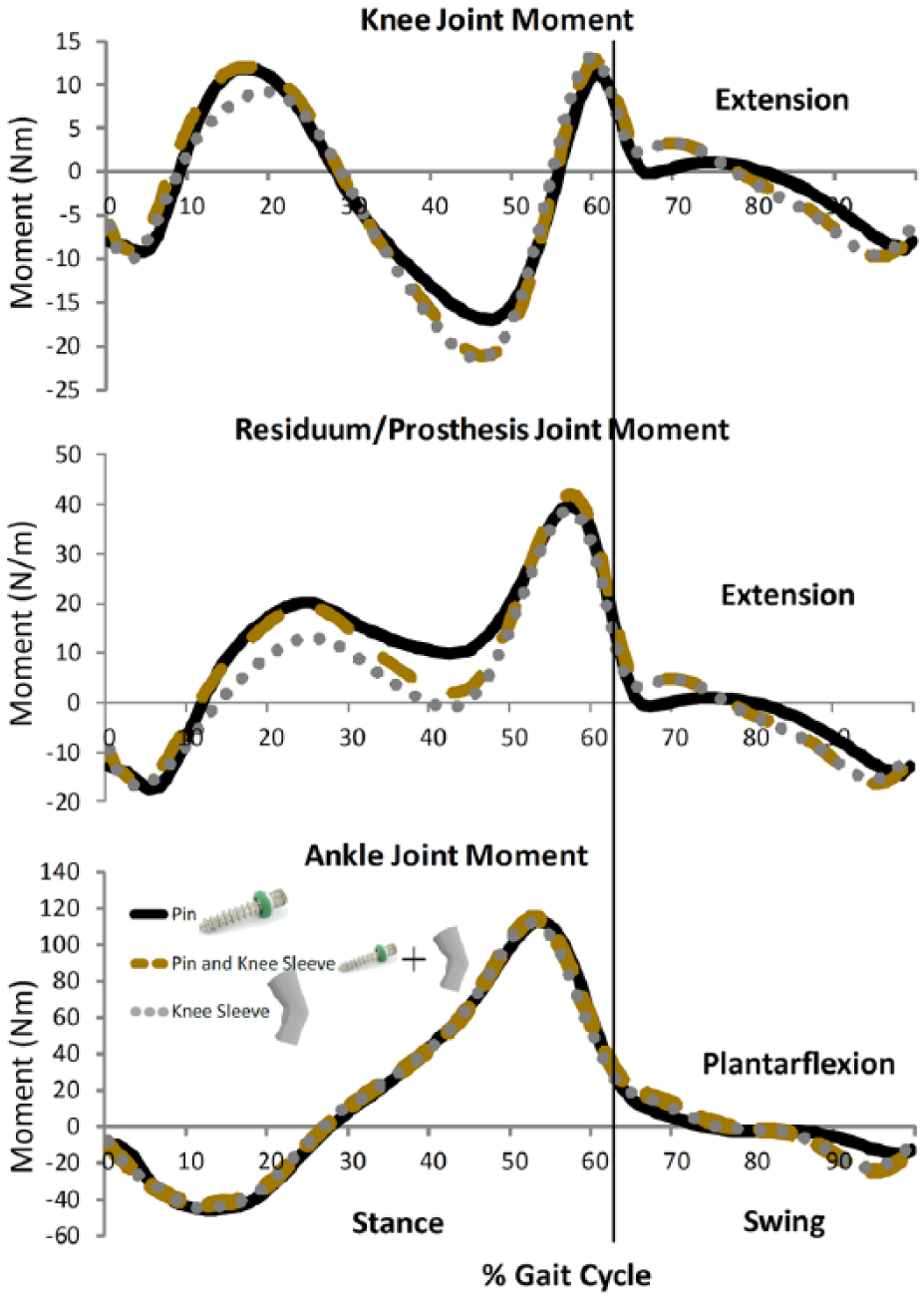
Joint moments for knee, residual limb–prosthesis pseudo-joint (RPJ), and ankle during gait.
The Monte Carlo simulation results indicated the accuracy and precision of the method to calculate limb segment motion based on skin markers (RMSE ± 1 standard deviation) was 0.81° ± 0.63°, 2.71 ± 1.20 mm, and 0.76 ± 1.08 mm for angular, proximal or distal, and anterior or posterior movements, respectively. The RMSE values for limb–prosthesis motion calculated based on skin markers and motion that included modeled bone–skin movements was 0.75°, 5.47 mm, and 1.86 mm for angular, proximal or distal, and anterior or posterior movements, respectively. The bone–skin movement generally increased translational movement but had little effect on angular movement (Figure 6).
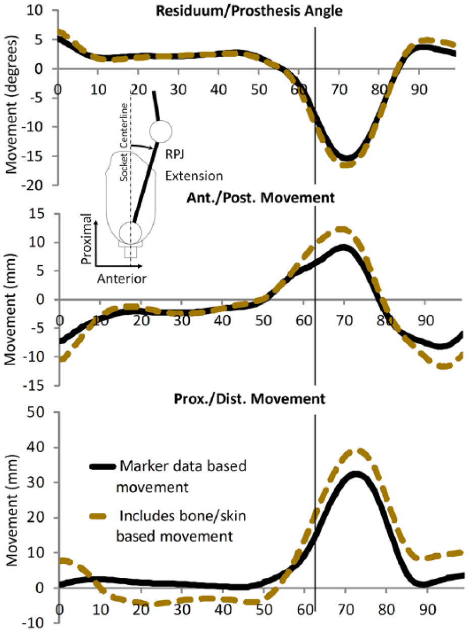
Movement between the residual limb segment (RPJ-RL) and prosthetic virtual marker (RPJ-P) during gait within the prosthesis coordinate system for trial 4 with (dashed line) and without (solid line) the addition of modeled skin–bone motion as simple linear spring. The inclusion of bone–skin movement increased the range of translational movement but had a minimal effect on the calculation of angular movement.
Pin suspension demonstrated significantly more angular range of motion than knee sleeve (p = 0.001) or pin + knee sleeve (p = 0.018; Figure 7). There was no difference between suspensions regarding translational range of motions.
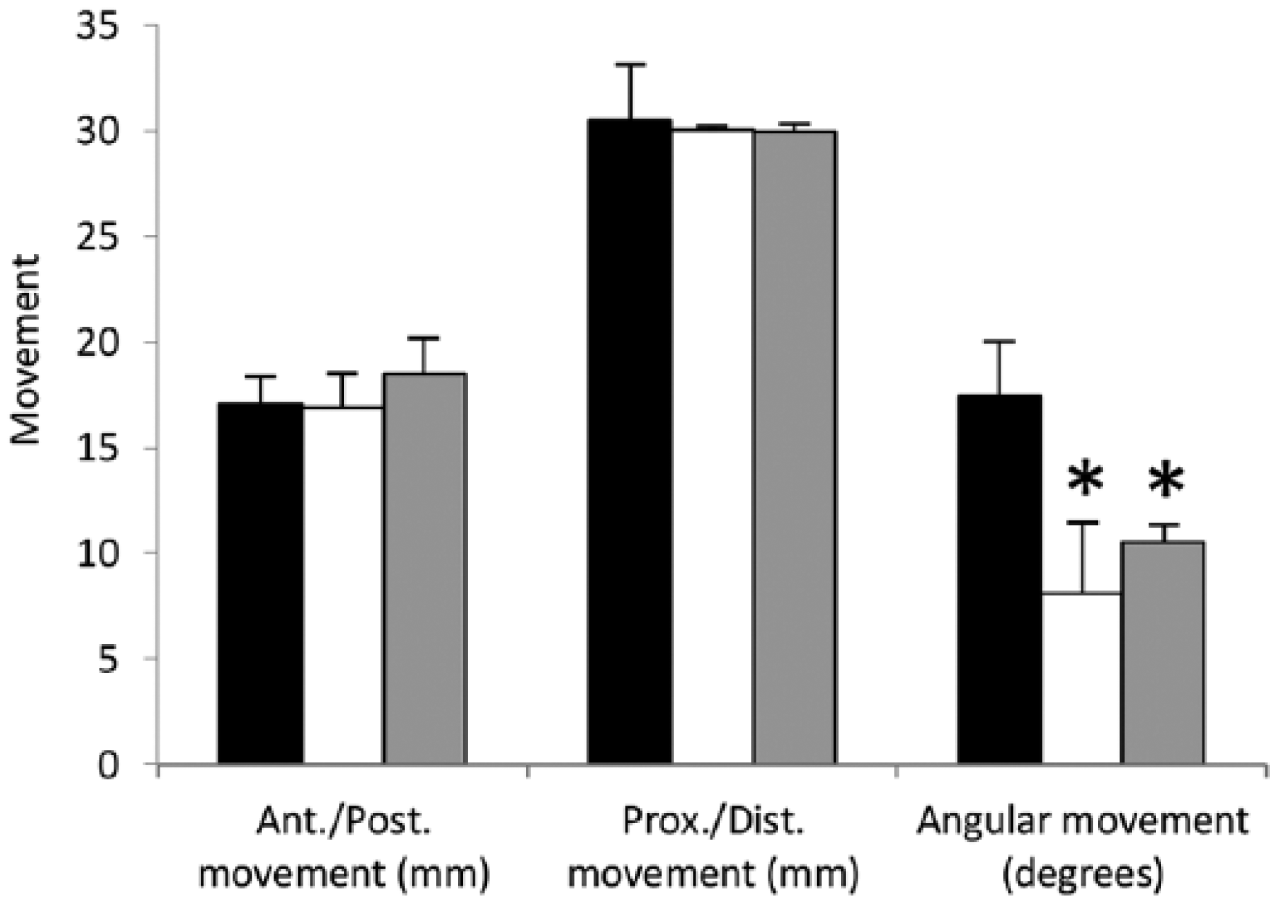
Range of motion for pin (black), pin + knee sleeve (white), and knee sleeve (gray) suspensions. The pin suspension demonstrated the largest range of angular motion compared to the pin + knee sleeve or knee sleeve suspension.
Discussion
This study describes a marker-based method to investigate the movement between the residual limb and the transtibial prosthetic socket. The residual limb segmental movement relative to the prosthesis was greater than the calculated RMSE and precision (Figure 3). The inclusion of a model to calculate the effect of bone–skin movement demonstrated differences (~5 mm) regarding proximal or distal translation with lower differences in angular and anterior or posterior translation (Figure 6). These errors were less than the range of motions measured, indicating the validity of this method (Figure 7).
Klute et al. 21 made an argument against marker-based measurements of limb–socket movement because of the soft tissue–skin’s inherit nature to move relative to the bone. This potential source of error was first minimized by having the marker baseplates on the skin and protruding through the gel liner. The addition of a gel liner effectively stiffened the residual tissues and reduced, but did not eliminate, this motion. 9 The effect of bone–skin movement was investigated with a simple model consisting of a linear spring between the skin at the ADT and the cut end of the tibia. The residual limb tissue stiffness was based on a worst-case scenario using maximum reported displacement of bone–skin movement, 9 and the model only allowed bone–skin movement at the ADT. If motion had been allowed at both the LEF and the ADT, then error between measured motion at the skin and motion at the bone would have been reduced because only a differential between the two points related to a tissue stiffness gradient between the LEF and the ADT would result in error. The model was intentionally biased to exacerbate error in order to compensate for potentially oversimplifying the modeling of residual limb tissue as a linear spring and to demonstrate how bone–skin movement would affect the measurement of residual limb movement based on skin markers. Errors due to bone–skin movement were most apparent in proximal or distal translation (RMSE = 5.47 mm), yet these errors were smaller than the overall movement recorded with the skin markers of ~32 mm (Figure 6). The RMSE values for angular movement were small (0.75°) relative to the motion recorded (20.5°). This is significant given the angular movement is least sensitive to bone–skin movement but demonstrated the greatest sensitivity to the type of suspension, and this movement is the most relevant to the calculation of joint moments. In addition, the stiffness of residual limb tissues is unlikely to change between experimental conditions meaning when experiments utilizing this method to compare motion relative to a baseline, it would effectively negate any error related to bone–skin movement. Therefore, although present, bone–skin movement should have a small effect on motion calculated using this method, particularly if angular movement is the variable of interest.
The method could be improved further if the array included more markers and was mounted more proximally on the shaft of the tibia where the bone–skin movement would have even less of an effect on measurement error. This arrangement would only require only cutting one rectangular hole over the shaft of the tibia. Using marker arrays on both the prosthesis and thigh would then allow for an instant center calculation with less variability using a helical axis method 22 and lead to an even greater simplification of future marker sets to quantify this motion.
This research provides some insight into residuum–prosthesis dynamics during gait, albeit in one individual. At initial contact, the residuum is more proximal, posterior, and in extension relative to the socket (Figure 3). Through loading response, the ADT is driven distally and anteriorly toward the prosthetic socket (Figure 3), and this movement may be responsible for common complaints of pain and irritation at the distal tibia just after initial contact. 23 Terminal stance and pre-swing includes residuum flexion and anterior movement (Figure 3) which would be necessary to create a moment about the prosthetic ankle joint in order to load the prosthetic forefoot for propulsion (Figure 4). 24 Swing phase dynamics are responsible for the majority of motion between the residuum and socket. The forces acting to move the prosthesis must overcome gravity and account for the limb’s inertial properties and the inherent stiffness of the suspension method utilized. Forward propulsion from the prosthesis is limited to the passive recoil of energy stored in the prosthetic foot, which must be supplemented by the coordination of joint torques in the sound and amputated limbs to pull the prosthesis up and forward. 25 These differentials between limited prosthetic foot propulsion, the mass and inertia of the prosthesis, and the pull from the amputated limb create forces that tend to stretch the residuum and suspension system. This could explain why the residuum is moving proximally and flexing relative to the socket during initial swing to accelerate the prosthesis up and forward (Figure 3). These movements peak at the end of initial swing, meaning the deceleration of the prosthesis occurs during mid-swing, which results in a posterior translation of the residuum relative to the socket (Figure 3). The relative proximal or distal movement during mid-swing to initial contact involves the residuum moving distally, whereas prior reports 26 predicted this would not occur (Figure 3). The distal movement of the residuum during terminal swing has been demonstrated in other studies16,27 and is likely influenced by several factors, including the recoil of residual limb tissues in conjunction with the recoil related to the mechanical stiffness of the suspension system, which overcomes inertial and gravitation forces related to swing dynamics of the prosthetic limb. More research is necessary on more subjects to fully understand this complicated dynamical system and the interaction of these factors.
Pin suspension demonstrated the most angular range of motion compared to the knee sleeve or pin + knee sleeve suspensions (Figure 7). This is likely because the mechanics of the knee sleeve inhibits the anterior or posterior motion of the knee joint relative to the prosthesis and because of how the residuum interacts with the prosthesis. This interaction can be seen in altered knee and residuum–prosthesis moments, while the ankle moment was maintained (Figure 5). The reorganization of joint moments at the knee joint and the pseudo-joint between the residuum and socket would have to be altered to maintain output about a joint not under direct control (ankle joint). Knee and socket moments have been demonstrated as a prosthetic control mechanism before during cycling 12 and create new opportunities for future research using this method to describe prosthetic control mechanisms during gait.
Prosthetic suspension systems that minimize limb–socket movement may also improve clinical outcomes because this would minimize the shear forces within the skin and residuum limb soft tissues that are linked to the development of skin ulcers. 14 These ulcers and other skin problems caused by tissue breakdown continue to be major inhibitors of prosthesis use,28,29,30 and they can occur from either shear forces acting directly on the skin or when the bone underneath displaces soft tissues as it moves relative to the skin. 14 The greater angular range of motion demonstrated with pin suspension would indicate that the soft tissues of the residual limb are going through larger ranges of shear and compression forces within those tissues, possibly leading to a higher risk of ulceration through the breakdown of tissues underneath the skin. Therefore suspension systems that minimize limb–socket movement (e.g. the combination of knee sleeve and pin suspension) may indicate improved prosthetic performance and limb health. 1
Conclusion
In conclusion, these data indicate a novel method, utilizing passive reflective markers, that is able to assess the relative motion between the residual limb and the prosthetic socket. Future research may use this (or similar) skin marker-based methods to evaluate prosthetic control mechanisms, prosthetic suspension systems, and socket designs that would lead to improved prosthetic suspension and rehabilitation strategies.
Footnotes
Acknowledgements
The authors gratefully acknowledge Dr Catherine Gubernatis Dannen for technical editing of this manuscript.
Author contribution
All authors contributed equally in the preparation of this manuscript.
Declaration of conflicting interests
The author(s) declared the following potential conflicts of interest with respect to the research, authorship, and/or publication of this article: The contents of this report do not necessarily represent the policy of NIDILRR, ACL, and HHS, and you should not assume endorsement by the Federal Government.
Funding
The author(s) disclosed receipt of the following financial support for the research, authorship, and/or publication of this article: The financial support for this research was provided by the National Institute on Disability, Independent Living, and Rehabilitation Research (NIDILRR grant number 90RT5024-01-00) to the Langston University Rehabilitation Research and Training Center (LU-RRTC) on Research and Capacity Building for Minority Entities through a collaborative subcontract with the University of Massachusetts Boston Institute for Community Inclusion (ICI). NIDILRR is a Center within the Administration for Community Living (ACL), Department of Health and Human Services (HHS).