
Abstract
Background:
Shear stress at the stump in trans-tibial amputees induced by turning movements may be reduced with the use of torsion adapters in the prosthesis.
Objective:
Monitoring the motion and kinetic effects of a regular torsion adapter in comparison to a rigid placebo in unplanned spin and step turns.
Study design:
Single-blinded placebo-controlled cohort study.
Methods:
In total, 10 trans-tibial amputees underwent three-dimensional gait analysis in level walking and unplanned spin and step turns with a torsion adapter and with a rigid placebo.
Results:
Kinetic effects varied among participants. No statistically significant reduction of peak internal and peak external transverse plane moments was found for the torsion adapter in any walking condition. However, transverse plane rotation of the adapter was monitored in all participants.
Conclusion:
Motion between the socket and the residual limb may be reduced during turns due to transverse plane motion of the torsion adapter and shear stress on the residual limb may be reduced. However, there may be good and bad responders to torsion adapters due to differences in coupling between the residual limb and the socket.
Clinical relevance
Strong coupling between stump and socket will help the user controlling his prosthesis. Shear stress at the stump may increase in stump–socket interface stiffness and may be the reason for residual limb problems. Torsion adapters therefore may be beneficial for comfort and stump condition in individual cases.
Background
A person with a lower limb amputation has to control the prosthetic limb in all three planes during walking via the socket establishing the interface between residual limb and prosthesis. In principle, the residual limb structures are not well suited for weight bearing and therefore excessive loads onto the residual limb should be avoided. Van der Linden et al. 1 describe the stump–socket interface as a joint allowing relative motion compensating for an absence of transverse plane motion among prosthetic components. Twiste and Rithalia 2 stated that circumferentially directed shear stress may be induced by angular motions of the residual limb within the socket and this motion is probably encouraged by moments acting in the transverse plane. Turning is an activity which has an effect on transverse plane moments as for instance Xu et al. 3 described. It can be performed via two basic strategies: the spin turn and the step turn as described by Hase and Stein 4 (Figure 1). Turning the contralateral side towards the stance limb corresponds to a spin turn (Figure 1(a)), and turning away from the stance limb matches a step turn (Figure 1(b)), respectively. A spin turn is considered to be the less stable movement because the base of support is as small as the surface of the stance limb foot during the turn. 5 A step turn is considered to be the more stable way to turn because stepping away from the stance limb spans a wider base of support to support the centre of mass (COM). 5 Turning is a mandatory task in everyday life to navigate within the environment. A video analysis study by Glaister et al. 6 showed that between 8% and 50% of steps can be recognized as a turning movement. Sedgman et al. 7 further pointed out that during every 10 steps, 2 turns are made to perform very basic functional activities such as making of a cup of tea. Presently, several companies for prosthetic components, for example, Otto Bock (Duderstadt, Germany), Össur (Reykjavik, Iceland), Fillauer LLC (Chattanooga, TN, USA) and Endolite (Sheffield, UK), offer torsion adapters to aid turning. These devices, either incorporated in a prosthetic foot or as a separate structural part, claim, for example, a ‘reduction of shearing forces otherwise transferred to the residual limb via the torsional function’ 8 or to ‘reduce both rotary forces on the knee joint and shear forces on the residual limb’. 9 Although notable research has been undertaken, potential benefits of torsion adapters in turns are still not fully proven. 2 Possibly, walking on a circular path as investigated, for example, by Segal et al.,10,11 Ventura et al. 12 and Neumann et al. 13 was not challenging enough and therefore effects reported were small. This assumption is supported by Courtine and Schieppati, 14 who stated that their unimpaired participants described steady state walking along a curved path as a ‘natural movement’ without high cognitive demands. Consequently, one has to distinguish turns also by how they are performed, either if it is a steady state movement or a ‘transient’ or ‘online’ turn, respectively. In this study, the focus is on the latter. Except for Taylor, 15 spin and step turns were never investigated in transtibial amputees (TTA). Taylor’s focus was mainly on strategic differences between unimpaired subjects and TTA and not on effects of torsion adapters. Segal et al. 10 argued in their study monitoring circular path walking that the biomechanical influence of a torsion adapter may be larger during a ‘transient’ turn. Hence, we assume that spin and step turns are more challenging than walking on a circular path and are therefore more appropriate to test functional benefits of a torsion adapter. To simulate the abrupt nature of a transient turn, we introduced a randomized cue as described by Patla et al. 16 and Kuni et al. 17 to simulate an unexpected situation and to reduce anticipatory compensating actions by the participants. Furthermore, we assume that peak ankle, knee and hip rotation moments would be reduced, most specifically again in unplanned turns.
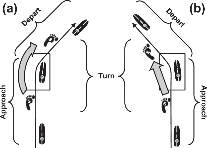
Schematic picture of (a) a right spin turn and (b) a left step turn with the according turn-phases approach, turn and depart (adapted from Dixon et al. 18 ). For TTA and unimpaired participants, a starting line was set such that the involved side (i) landed on the force plate. Landing on the involved side and turning with the sound side (s) towards the involved side corresponded to a (a) spin turn, and landing on the involved side and turning away from that side matched a (b) step turn, respectively. In this study, only the data for turn phase are considered.
It was therefore explicitly evaluated in a randomized manner, whether TTA benefit from a torsion adapter integrated in the prosthetic foot Vari-Flex® XC Rotate™ (Össur) during level walking and in unplanned spin and step turns. During experiments, the participants were blinded in the sense that they were not aware whether they were using a regular torsional adapter (R) or a similar looking placebo adapter (P) without any functional effects.
Methods
Participants
In the study, 10 participants (45 ± 17 years, 178 ± 8 cm, 77 ± 12 kg) with nonvascular unilateral trans-tibial amputation and level 3–4 in Medicare Functional Classification 19 were included. Excluded were TTA with current residual limb problems, such as oedema, pressure sores or wounds. The subject and prosthesis characteristics of the 10 users which were recruited are given in detail in Table 1. For reference, 10 participants (33 ± 10 years, 179 ± 9 cm, 72 ± 17 kg) without any gait impairments were examined. Written, informed consent was given by TTA and reference participants. The study was approved by Heidelberg University Hospital Ethics Committee. 20
Subject and prosthesis characteristics.
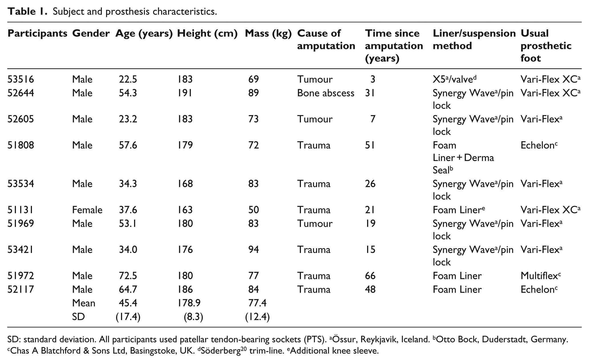
SD: standard deviation. All participants used patellar tendon-bearing sockets (PTS). aÖssur, Reykjavik, Iceland. bOtto Bock, Duderstadt, Germany. cChas A Blatchford & Sons Ltd, Basingstoke, UK. dSöderberg 20 trim-line. eAdditional knee sleeve.
Examinations
With reference to their regular prosthesis, recruited users first completed an abbreviated version of the Prosthesis Evaluation Questionnaire (PEQ) 21 translated to German which comprised the scores utility, sound, frustration, ambulation, well-being and satisfaction. They were provided with a Vari-Flex XC Rotate (Össur) with the regular torsion adapter (R) to be used for the next 2 weeks with the socket of their regular prosthesis. TTA participants were not informed about any specific features of the prosthetic foot. Static and dynamic prosthesis alignment was controlled for all participants by the same prosthetist according to the guidelines of the manufacturer 22 and with the use of a L.A.S.A.R. Posture (Otto Bock) as described by Blumentritt.23,24 Furthermore, the users were asked to keep a diary during this adaptation period as described by Block et al. 25 In this diary, the participants were asked to note any perception they had during the test period when comparing to their regular prosthesis. Additionally, they should note detrimental events such as socket problems and/or any therapeutic interventions, for example, gait education. After the 2-week test period, the participants underwent specific gait and turning tests. They further filled in the PEQ a second time with reference to the tested prosthesis with the regular torsion adapter (R). In general, the sequence of measurements was randomized between participants. The placebo adapter (P) did not have any specific torsion function but its appearance was similar to the regular torsion adapter (R). Before monitoring turning manoeuvres, the prosthetist took the prosthesis to another room pretending ‘to prepare it for measurement’ such that the torsion adapter could be exchanged either to R or P condition. By this procedure, it was controlled that the user was unaware of which adapter he was presently using. After a first series of turning manoeuvres and level walking with one of the adapters, the prosthetist exchanged it with the other one, again blinded for the participant and the test series was repeated. TTA were not informed that the prosthesis was modified, neither they were encouraged to describe their perception for the prosthesis during experiments. For the turning tests, TTA were asked to walk straightforward on a walkway at self-selected speed. At a predefined point along the walkway (60 cm + 1/2 step length ahead of the force plate), they got a randomized visual cue via a photoelectric switch indicating them to either turn 45° to the left or to the right (Figure 2). Lines on the floor showed the 45° corridors. Foam blocks on the end of the lines helped to guide the participants to stay within the corridor. The starting line was set such that the involved limb landed on the force plate. Consequently, landing on the involved side and turning towards the involved side corresponded to a spin turn, and landing on the involved side and turning away from that side matched a step turn, respectively (Figure 1). If there was no visual cue, the participant had to walk straight on. Measurements for the non-dominant side of reference participants were performed in the same manner. For comparisons, the non-dominant side of unimpaired subjects was associated with the involved side of amputees.
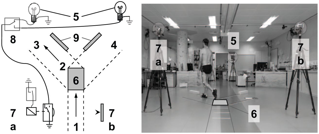
Schematic (left) and actual experimental setup (right) for turns: (1) walking direction; (2) turning direction (exemplarily to the left); (3) left turn corridor; (4) right turn corridor; (5) (right) visual cue; (6) force plate; (7a) photoelectric switch (with relay and reset switch) (7b) reflector of photoelectric switch; (8) changeover switch for left, or right cue, respectively and (9) foam blocks.
Data collection, processing and analysis
For monitoring turning manoeuvres and level walking, the participants were prepared with reflective markers according to standards of clinical gait analysis procedures, namely, using a marker-set for the Plugin Gait (PiG) lower body model (Vicon, Oxford, UK) based on Kadaba et al. 26 For below knee amputees, the knee marker (lateral femoral epicondyle) was placed onto the lateral aspect of the prosthetic socket – which typically covers the knee joint – coinciding with the approximated centre of rotation of the knee joint according to Nietert. 27 When a knee sleeve was used, the knee marker was placed onto the sleeve in the same manner. A shank wand marker was placed onto the prosthetic pylon proximal to the torsion adapter. The ankle marker (Figure 3(a) to (c); marker 2) was placed onto the prosthetic foot distally to the torsion adapter. Kinematics and ground reaction forces were collected by means of a 12-camera system (Vicon) operating at 120 Hz and two force platforms (Kistler Instruments, Winterthur, Switzerland). Standard modelling procedures were applied (Plugin Gait, Vicon) for calculating joint kinematics and joint moments of hip, knee and ankle, except for the rotation of the torsion adapter which was calculated by a separate procedure. In the absence of the anatomic foot and ankle, the torsional moment of the adapter was determined in TTA as the transverse plane ankle moment via PiG. The rotation of the torsion adapter was calculated as projection angle as described by Crawford et al. 28 or more in detail by Simon et al. 29 in Appendix B. The attitude of two body-fixed vectors, one distally and one proximally to the torsion adapter, is projected into the plane perpendicular to the rotational axis of the adapter. The distal segment vector is defined by markers 1 and 2 and the proximal segment by the markers 3 and 4, respectively (Figure 3). The rotational axis, that is, the projection plane is equivalent to the long axis of the shank defined by the two midpoints between markers 1 and 2 and markers 3 and 4, respectively.
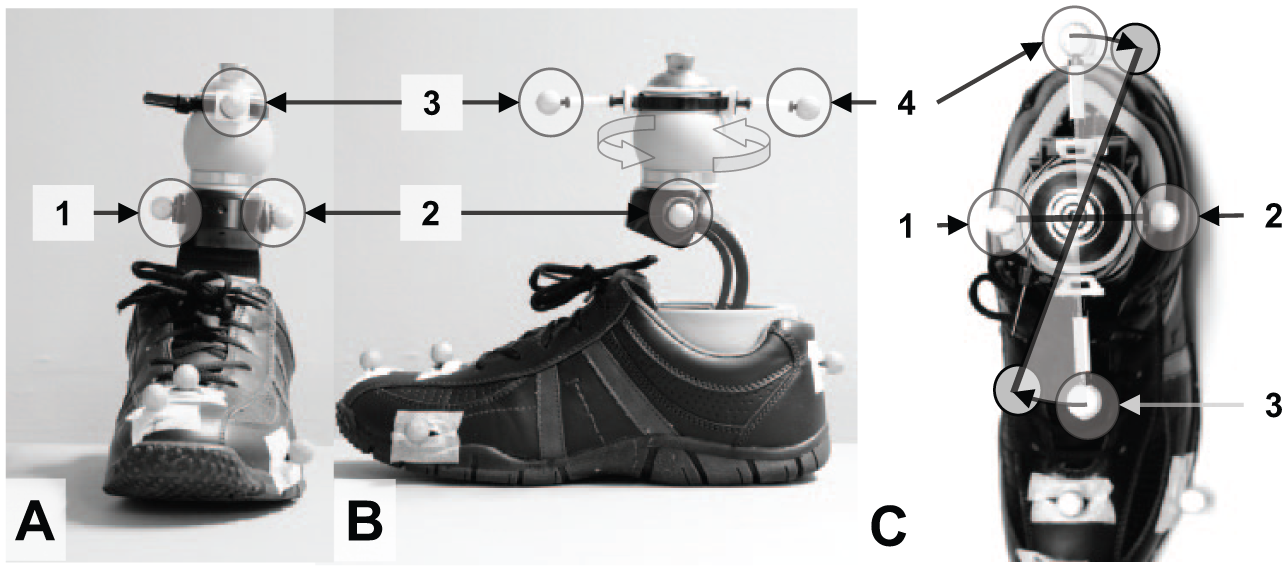
Additional marker placement to detect transverse rotation in (a) frontal view, (b) sagittal view and (c) transverse view. The ankle markers (1 and 2) are placed distally to the torsion adapter (large grey ball), two more markers (3 and 4) are placed proximally to it to determine rotational motion around the long axis of the shank as projection angle.
A static trial was used to set the neutral angle of torsion adapter. All participants were provided with the same type of standard shoes shown in Figure 3 (Deichmann, Essen, Germany) except for one subject who used her own jogging shoes (51131). Heel and toe markers were placed onto the shoe.
For each task (level walking, step turn and spin turn), at least five valid trials were captured of the involved side in TTA and the non-dominant side in reference participants. Data of level walking were available for 9 out of 10 TTA. A spline filter routine (VCM; Vicon) was used to filter trajectories of each trial. Finally, time series (joint angles and moments) were averaged across repetitions. Peak internal and external moments for the ankle, the knee and the hip were extracted for early and late stance (i.e. 0%–30% and 30%–70% of the gait-cycle (GC), respectively) in level walking and for the turnings tasks (Table 3). Gait speed was calculated via sacrum marker velocity. Differences between P and R conditions were calculated for all three walking tasks by a two-tailed Wilcoxon Signed-Rank Tests for paired samples. Differences between TTA and unimpaired participants were identified by a two-tailed Mann–Whitney Test for independent samples. Level of significance was set at p ⩽ 0.05.
Results
Gait speed
TTA walked significantly slower than reference participants during level walking (reference 1.46 ± 0.18 m/s; TTA (P) 1.26 ± 0.08 m/s; TTA (R) 1.28 ± 0.06 m/s; reference vs (P) p = 0.018; reference vs (R) p = 0.008), step turns (reference 1.19 ± 0.10 m/s; TTA (P) 1.06 ± 0.06 m/s; TTA (R) 1.06 ± 0.06 m/s; reference vs (P) p = 0.010; reference vs (R) p = 0.010) and spin turns (reference 1.20 ± 0.09 m/s; TTA (P) 1.07 ± 0.06 m/s; TTA (R) 1.07 ± 0.07 m/s; reference vs (P) p = 0.004; reference vs (R) p = 0.004) in both conditions P and R. There were no significant differences in gait speed between TTA in R and P condition measurements for level walking and turns (P vs R level walking p = 0.594; step turn p = 0.678; spin turn p = 0.953).
Transverse plane kinematics and kinetics of the torsion adapter
In both the level walking condition and in turning manoeuvres, the adapter (R) showed a significantly larger transverse plane motion compared to the placebo condition (P; Table 2). For the kinetics in spin turns, only peak external rotating ankle moments showed significantly higher values for condition R compared to P (Table 3; B; Figure 4). In level walking, significantly higher peak internal rotating ankle and knee moments were found for condition R (Table 3; A).
Mean range of torsion adapter transverse plane rotation in stance.
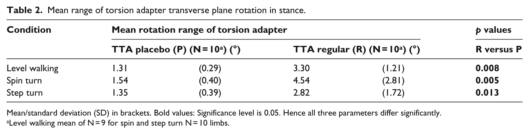
Mean/standard deviation (SD) in brackets. Bold values: Significance level is 0.05. Hence all three parameters differ significantly.
Level walking mean of N = 9 for spin and step turn N = 10 limbs.
Peak external (A1, K1, H1) and internal (A2, K2, H2) moments as defined in Figure 4.
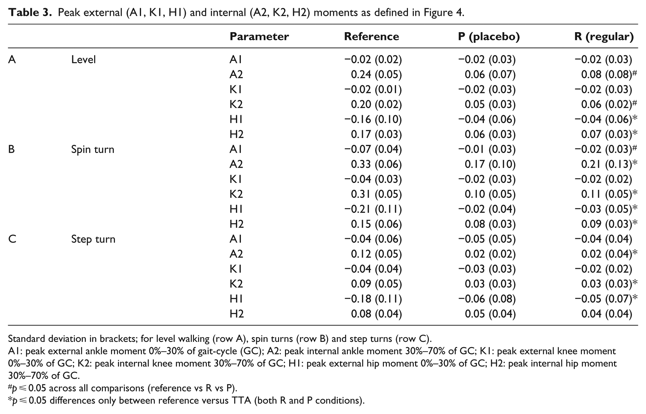
Standard deviation in brackets; for level walking (row A), spin turns (row B) and step turns (row C).
A1: peak external ankle moment 0%–30% of gait-cycle (GC); A2: peak internal ankle moment 30%–70% of GC; K1: peak external knee moment 0%–30% of GC; K2: peak internal knee moment 30%–70% of GC; H1: peak external hip moment 0%–30% of GC; H2: peak internal hip moment 30%–70% of GC.
p ⩽ 0.05 across all comparisons (reference vs R vs P).
p ⩽ 0.05 differences only between reference versus TTA (both R and P conditions).
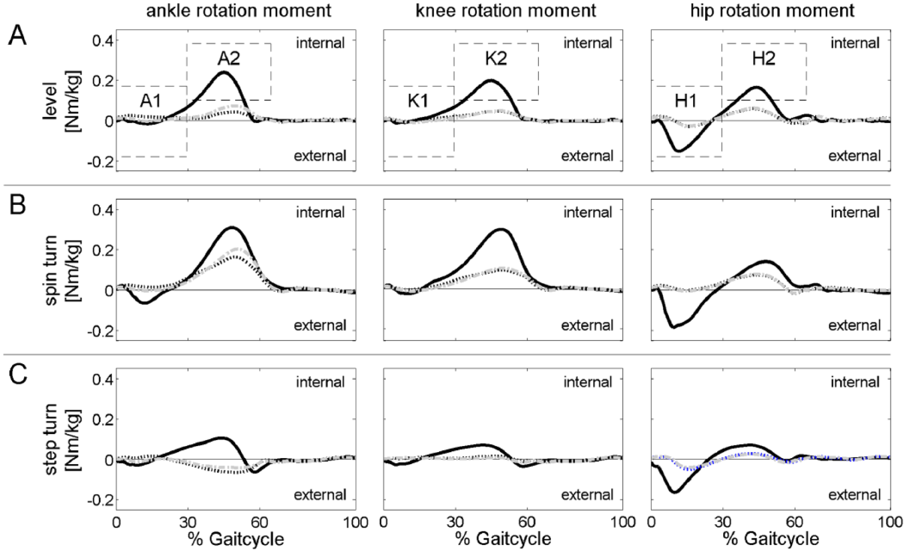
Transverse plane moments (mean TTA involved side, non-dominant side reference) for (a) level walking, (b) spin turns and (c) step turns; solid black line denotes the reference participants, black dotted line P (placebo adapter), grey dash-dot line denotes R (regular adapter), displaying standard deviation has been omitted for reasons of clarity definition of parameters: A1: peak external ankle moment 0%–30% of GC; A2: peak internal ankle moment 30%–70% of GC; K1: peak external knee moment 0%–30% of GC; K2: peak internal knee moment 30%–70% of GC; H1: peak external hip moment 0%–30% of GC; H2: peak internal hip moment 30%–70% of GC).
TTA participants’ feedback
No statistical differences were found between the prosthesis commonly used and the newly fitted Vari-Flex XC Rotate with the R adapter for any of the PEQ scores (utility, sound, frustration, ambulation, well-being and satisfaction). According to the diaries, none of the participants reported unusual events, for example, socket problems during the test period. Furthermore, the following advantages and disadvantages in context with the torsion adapter were extracted: 2 out of 10 TTA reported that moving in constricted room and during turns is more comfortable with the test prosthesis. In total, 2 out of 10 TTA reported an ‘odd’ or ‘unusual’ perception during turns for the additional degree of freedom offered by the adapter. One TTA reported an insecure feeling while ascending stairs. None of the TTA reported on any effects of the torsion adapter during level walking. During data collection, 2 out of 10 TTA clearly stated that transverse plane rotation is absent when switching to the placebo adapter, although TTA were not encouraged to describe their perception during the experiment.
Discussion
To our knowledge, this is the first study to explicitly quantify the turning motion of a torsion adapter in step and in spin turns. Thus, 3° of transverse rotation with the regular adapter averaged across participants was detected in spin turns, followed by 1.5° in step turns (Table 2). The effects of the regular torsion adapter (R) on the transverse plane moments for TTA involved side were heterogeneous. Inter-individual differences in peak transverse plane moments – indicated by large standard deviations compared to the data of the reference (Table 3) – are independent of conditions P and R. Hence, we found no statistically significant reduction of transverse plane moments for the regular adapter in any walking condition. On the contrary, there was a small but significant increase in peak external rotating ankle moment for the torsion adapter in comparison to the placebo condition during spin turns and increased internal rotating ankle and knee moments in level walking. However, it seems that some participants in fact did benefit by the regular torsion adapter with a reduction of transverse plane moments while others did not. For example, participant 53516 showed a reduction of peak internal ankle moment for spin turns when using the R adapter (0.09 N m/kg) when compared to condition P (0.14 N m/kg), while participant 51131 showed an increase for that parameter when using the R adapter (0.19 N m/kg as compared to 0.09 N m/kg). Similarly, subjective feedback of the users was partly in favour of the torsion adaptor and partly not (see TTA participants’ feedback). Reasons for individual differences in transverse kinetics during turning could be differing physical capabilities, prosthesis alignments, or, most importantly, differences in socket design. Suspension methods varied within this study (Table 1). Van der Linden et al. 1 stated that the lack of transverse plane motion of conventional prosthetic components has to be compensated by proximal joints and they identified the stump–socket interface as a joint allowing transverse plane motion. In this context, we propose a model of a serial chain of two torsion springs to explain the inter-individual findings: Both the stump–socket interface and the torsion adapter represent a joint which is moving in the transverse plane with an individual stiffness (moment/angular motion). In this chain, the spring with the lower stiffness will rotate as soon as the system is exposed to a transverse plane moment. No statistical differences in the average transverse plane moments between P and R adapter condition lead to the hypothesis that the moments which induce rotational motion in the torsion adapter will probably induce stump–socket interface motion in the placebo condition. Hence, the circumferential shear stress at the stump–socket interface as described by Twiste and Rithalia 2 possibly will be larger in P condition. It is likely that in this study, we monitored these effects and that the stump–socket interface acts as the proximal joint with respect to the prosthetic components, in particular in P condition. Users with a ‘tight’ and ‘close’ connecting stump–socket interface will probably demonstrate higher stump–socket interface stiffness. One could argue that the ‘stiffer’ the torsional coupling between the residual limb and the socket, the more the TTA will benefit from a torsion adapter. A number of torsion adapters offer the possibility to change transverse plane stiffness (e.g. DeltaTwist®; Otto Bock). 8 The R adapter tested in this study did not offer an adjustable stiffness and therefore could not be modified to different prosthetic suspension methods and their associated stiffness.
Limitations
In total, 2 weeks of acclimatization was given for the R adapter, but no acclimatization period was given for the P adapter, which was only used during experiments. The additional markers at the adapter allow monitoring transverse plane motion of this torsional adapter. However, their placement is a compromise between feasibility and precision. With distances of only a few centimetres, the angular precision does not exceed 1.5° as monitored in the placebo adapter which as such should stay rigid showing no movement at all. These movements in P condition (Table 2) are addressed to optical noise in marker capturing as reported by Richards. 30 Consequently, this noise has to be subtracted from the peak rotation ranges in R adapter condition. An alternative method by Twiste et al. 31 using an instrumented prosthesis promises higher accuracy but due to the extra experimental effort was not used here. Furthermore, shear stress has not been directly tested hence any implication to this effect remains on a hypothetical level to be confirmed in further studies.
Conclusion
The results indicate that torsion adapter may reduce shear stress on the residual limb structures at the stump–socket interface in trans-tibial amputees when performing unplanned turns. At best, the socket design should be controlled in future studies to clearly identify benefits of torsion adapters and to single out possible differences or shortcomings in socket-fit. For the prescriber, it is important to know that in individual cases, torsion adapters are beneficial. Further work should be directed towards determining which parameters affect the outcome to decide who is a ‘good responder’ to a torsion adapter. Shear stress at the stump–socket interface could be possibly studied in the future to prove our hypothesis of a serial chain of torsion springs. Torsion adapters may further be optimized, for example, by adapting torsional stiffness to suspension method and activity of the amputee.
Footnotes
Acknowledgements
We gratefully acknowledge the time and effort of all participants.
Author contribution
All authors contributed equally in the preparation of this manuscript.
Declaration of conflicting interests
The author(s) declared no potential conflicts of interest with respect to the research, authorship, and/or publication of this article.
Funding
The author(s) disclosed receipt of the following financial support for the research, authorship, and/or publication of this article: This research project was financially supported by Össur HF Reykjavik, Iceland.