
Abstract
Knowledge of internal ballistic pressure and projectile velocity is required to ensure gun safety, reliability, calculation of its range, and evaluation of ammunition. However, existing methods for determining the same are either overly complex, costly or have limitations in their applicability. In this work, the authors address this need by proposing a reliable, simple, cheap, and non-destructive method for determining in-bore pressure, projectile velocity, and acceleration profile using strain measurements. Data from strain gauges were used to detect the projectile’s arrival time at different locations in the barrel and computed projectile velocity and acceleration as a function of projectile position. Finally, acceleration data was used to calculate the pressure behind the projectile. Results were verified using alternative experimental and simulation techniques on two different barrels with different ammunition. It was found that the proposed method works well and thus can be reliably used in similar applications elsewhere.
Introduction
The in-barrel pressure of a gun impacts gun-safety, and in-bore projectile velocity. Knowledge of its peak value is often used to design the barrel. In-barrel pressure data is also used for propellant characterization and estimation of temperature rise inside the barrel. Thus, it is essential to measure in-barrel pressure accurately. It is also vital to accurately measure projectile velocity 1 inside the gun barrel as such knowledge helps in the estimation of burn rate and chemical composition of the propellant, calculation of pressure behind the projectile, estimation of barrel erosion and wear, optimization of propellant mass in designing a barrel’s rifling grooves. However, there are significant limitations associated with several existing methods for measuring in-bore pressure and projectile velocity. A review of such methods is provided further. This work proposes a new way of determining the projectile velocity as well as pressure inside the bore at once using strain measurements.
Existing velocity measurement methods
The velocity of the projectile inside the barrel changes very rapidly over a very short duration. Quite often, the projectile velocity is determined from the pressure curve. In such a situation, the effects of friction, band pressure, the interaction between gas pressure and the bore on projectile velocity cannot be easily accounted for. Also, such an approach does not yield sufficiently accurate estimates of muzzle velocity, range, and circular error probable (CEP) radius.
Microwave Interferometry2,3 is another popular method for measuring in-bore projectile velocity. However, its effectiveness is strongly dependent on the shape of the projectile tip, the nature of combustion gases, and the characteristics of the recoil system. Further, the method requires a reflecting surface, which needs replacement after each round of firing. A related method, ‘VISAR’ (Velocity Interferometer System for Any Reflector),4–7 takes advantage of the Doppler phenomenon in laser beams to measure in-bore projectile velocity. However, such a method can yield significant errors due to the presence of shock heating of ambient gases. Further, such a method is very complex and thus difficult for commissioning. 8 Photo-tonic Doppler Velocimetry (PDV) is another method used for measuring velocity 9 and acceleration 10 for in-bore applications. Though PDV technology is relatively easy-to-use, its efficiency is limited due to the opacity of the gaseous medium in the barrel due to the generation of the shock front in the gun bore. 7 Shock Wave Pressure Sensors 11 are useful for measuring projectile velocity outside the barrel.
Then there is the solenoid velocity coil method. 3 In this method, two solenoid coils are used. One such coil is wound outside the barrel, and the second one is attached to the projectile. When the projectile with a magnetized coil passes through the barrel, it cuts the magnetic lines created by the outer coil, and an electromotive force is induced in the former. Such a phenomenon is used to determine the time of arrival of the projectile corresponding to different locations. However, the method requires modification to the projectile body, which is not desirable. Further, in the presence of large ferromagnetic bodies, the method is prone to errors due to non-linear effects.
Break screen and panel 3 are also used to determine projectile velocity. In such methods, paper sheets printed with electrically conductive grids are positioned in the path of projectile at several locations. These grids break when the projectile passes through the bore, and thus the time of arrival of the projectile is recorded. However, the method requires the replacement of paper after each round of firing. Also, this method is not suitable for velocity measurement at positions located deep inside the barrel. In the Lumiline, Sky screen, and optical screen12,13 methods, a beam of light is focused on a screen. 3 When the projectile passes by the screen, the intensity of light changes significantly, and such a change is used to determine to identify the time of arrival of the projectile. However, this method is also not suitable for in-barrel velocity measurement. High-speed photography14,15 is also incapable of measuring in-barrel measurements. Then there is flash radiography, 16 which relies on X-rays to measure the projectile velocity. This method is effective but also expensive and complex. Another approach involves the use of onboard tri-directional accelerometers 17 and magnetic field sensors. 18 Despite their effectiveness, the technique requires modification to the projectile and hence is not very popular. In-barrel projectile velocity can also be obtained by drilling holes in barrel, and placing mechanical, or optical switches in the holes which get activated or deactivated once the projectile pass the holes locations. However, such a method requires modification to the gun barrel. In a different work, LaVigna et al. 19 measured the ‘Round Exit Velocity’. However, such a method does not provide information on the projectile inside the bore.
Existing pressure measurement methods
Crusher gauges 20 have been in vogue for measuring peak pressure values generated inside a barrel. However, such a method cannot be used to record the pressure variation inside the barrel. Post-1960s piezoelectric transducers have been increasingly used 20 for in-bore pressure measurements. Using them requires a hole to be drilled in the barrel for mounting such sensors.21,22 In the process, the barrel gets weakened and cannot be used in the field. There are also miniature piezo sensors,23–25 which are sometimes placed inside the barrel during firing. Such sensors have onboard power and memory and provide sufficient accuracy and reliability. However, such technology is very costly and requires accurate and frequent calibration.
This work uses strain-gauges attached on the outer surface of the barrel at known distances. Strain measured using strain gauges gives the time of arrival of the projectile at specific barrel location. The projectile velocity has been calculated from the time of arrival. To obtain the velocity-displacement curve, a curve is fitted to the velocity points. The acceleration-displacement curve is calculated from the velocity-displacement curve. The force exerted on the projectile by the gas can be calculated using the force-acceleration relation. Finally, the pressure force relation produces the pressure curve behind the projectile. Barrels can be strengthened using various methods, and several factors, including these methods influence the hoop strain value. Consequently, our focus is not solely on the peak value of the hoop strain. Instead, we are interested in determining the time at which the peak strain occurs. This information allows us to generate velocity curves and develop pressure curves, rather than directly estimating pressure from hoop strain. As a result, our methodology is applicable to all types of barrels including those that have undergone processes such as autofrettage and shrink fitting. Such a method offers simplicity, cost-effectiveness, nondestructiveness, independence from the barrel material, suitability for implementation on a working gun, and long-term calibration stability once installed. Operators with less expertise can easily perform the experiments. In the study, two barrels were employed: one was an autofrettage barrel, and the other was a partially jacketed/shrink-fitted barrel, which served for additional validation in the subsequent section.
Materials and methods
As a projectile passes by a specific cross-section of the barrel, a hoop strain gets developed on the barrel surface due to the sudden rise of pressure behind the projectile and also due to the generation of band pressure. Thus, a strain gauge will sense a sharp spike in the strain at the very moment when the projectile passes by its location. However, the value of such strain cannot be directly used to calculate the gas pressure behind the projectile due to two reasons. First, the strain value is due to the combined effects of band pressure as well as gas pressure. And two, the material of the barrel exhibits non-linear elastoplastic behaviour. However, these spikes in strain can work as excellent indicators of the Time of Arrival (ToA) of the projectile at different strain gauge locations. Thus, the ToA of the projectile at successive barrel cross-section can be measured, and such ToA data can then be used to calculate in-barrel projectile velocity. This is a non-destructive method as it requires no modification to either the barrel or the projectile. The velocity curve can also be used to compute the acceleration of the projectile, which in turn can be used to calculate the pressure required behind the projectile. Based on such a concept, an experimental setup for determining in-bore projectile velocity and gas pressure was developed.
Experimental setup
Figure 1 shows the schematic layout of the experimental setup used in this work. As shown in the figure, the ToA of the projectile moving in a 4 m long test barrel tested in the field using live firing was experimentally determined at seven different positions, using a pair of strain-gauges for each location. Using such ToA data, the velocity at the mid-point of each pair of gauges was calculated by taking the ratio of the distance between sensor locations of each set and the corresponding difference in the ToA of the projectile. The authors used 350
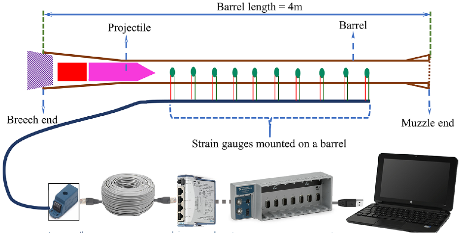
Schematic of the experimental setup and data acquisition system.
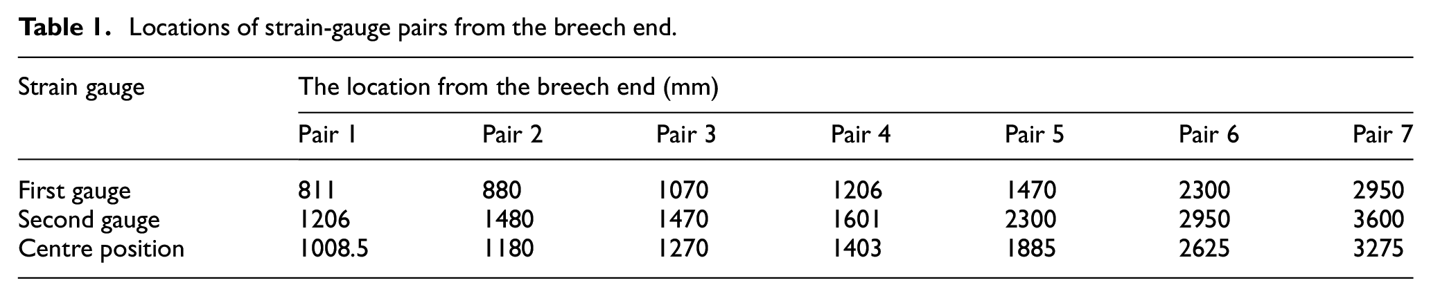
Locations of strain-gauge pairs from the breech end.
Data was acquired at a sampling rate of 50 kS/s. Such a rate of sampling was considered sufficient, as it would take at least 0.56 ms for the projectile to move between two adjacent strain-gauge locations within a typical ‘Pair’ corresponding to the maximum possible projectile velocity of 700 m/s. Over this period, the data acquisition system would acquire 28 data points at a sampling frequency of 50 kS/s. This would be sufficient for our needs. In addition to strain-gauges, proprietary copper crusher gauges to measure peak pressure in the barrel during each firing cycle was also used.
Results and discussion
Figure 2 shows strain plots for a typical strain-gauge pair mounted on the barrel as a projectile pass through its position. It is seen from the figure that when the projectile band passes by the strain-gauge location, the hoop strain in the barrel rises suddenly to a peak value. The timing of this event (points A and B in Figure 2) corresponds to the ToA of the projectile. 26 Such ToA data was used to calculate the projectile velocity at different locations along the barrel length. Strain values were used only to determine the ToA which eliminates the need for material properties in determining internal pressure, projectile velocity, and acceleration.
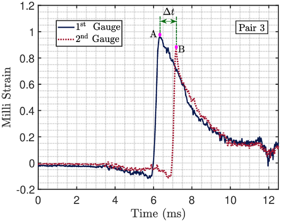
Hoop strain recording from a pair of strain-gauges.
Projectile velocity and acceleration
Figure 3 shows the variation of normalized projectile velocity as it traverses the barrel length. A curve is fitted to the experimentally determined projectile velocity, and its equation is given below.

where,
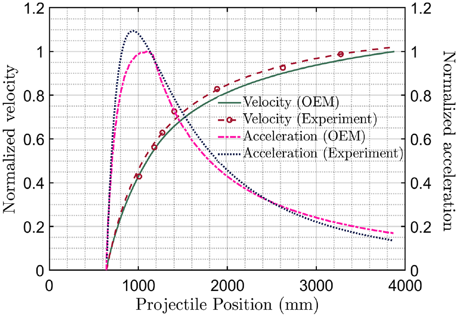
Normalized velocity and acceleration plots of the projectile. Velocity and acceleration data were normalized with respect to maximum values of OEM velocity and acceleration as provided by the OEM.
It is seen from the figure that the estimated velocity curve as prescribed by equation (1) is in very good agreement with corresponding data provided by the OEM. It was also noted that experimental estimates on acceleration match with OEM data reasonably well except in the peak region. Such divergence can be significantly reduced using more sensors on the barrel, especially in its breech-end part. The experimental conditions, such as ammunition properties, barrel dimensions, and the volume available in the combustion chamber were utilized by OEM to compute pressure and velocity versus projectile travel using SIMBIB software.
The pressure behind the projectile
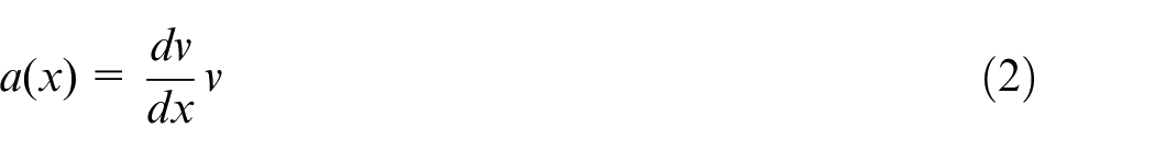
Next, the relation for acceleration was used to calculate the value of pressure just behind the projectile as a function of projectile position. In the absence of friction, projectile acceleration and gas pressure
Here
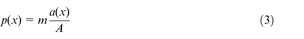
Figure 4 shows the plot of the normalized pressure curve calculated this way. Also shown in the figure is a plot of the pressure curve as provided by the original equipment manufacturer (OEM) using SIMBIB software and the peak value of pressure in the barrel as measured by a crusher gauge. The base of the projectile used in the study had a boat tail shape with 4°−5° taper angle. The following observations can be noted from this figure.
There is reasonable agreement between pressure values as provided by the OEM and corresponding calculated estimates of the same based on ToA data.
However, the peak value of pressure as provided by the OEM is 6.1% less than the corresponding value based on measurements. This difference is attributed to the fact that strain gauge pairs were not spaced sufficiently close enough to accurately detect the peak pressure. This limitation can be addressed by placing more sensors at closer spacings, especially in the region where pressure is expected to peak.
The peak pressure recorded by the crusher gauge is more or less the same as the value provided by the OEM.
As the projectile approaches the muzzle end, the difference in pressure as calculated by the proposed method and as that provided by the OEM increases. This divergence attribute to the fact that gauges were separated by larger distances at the muzzle end.
Comparison of pressure results. Pressure is normalized with the maximum value of OEM pressure data.
Further validation
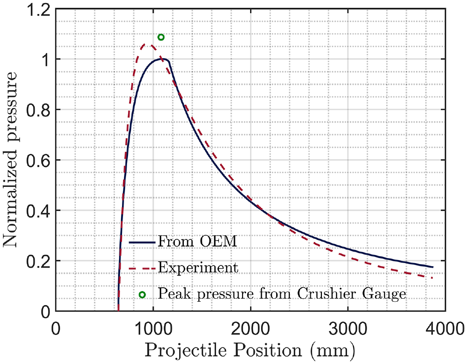
To further verify the proposed method’s accuracy, an additional field experiment was conducted on a gun with a different bore diameter and a different type of ammunition. For this experiment, we used a 6 m long barrel and four strain gauges were bonded to the barrel. The location of strain gauges were 4.31, 3.60, 2.80 and 0.20 m away from the muzzle end of the barrel. In such an experiment, strain data was recorded. Also, in-bore pressure data were obtained from the OEM. In-bore projectile velocity was also calculated using these pressure data. The comparison of in-bore projectile velocity gotten from the proposed procedure against OEM data is shown in Figure 5. Reasonable agreement is seen between the two estimates. In this figure, we have not plotted pressure curve based on experimental data because of a limited numbers of strain gauges used in the experiment.
Pressure and velocity curve for a new barrel and with a new ammunition. Pressure is normalized with the maximum value of OEM pressure data and velocity is normalized with the maximum value of OEM velocity.
While the dependency of the pressure curve on material properties is eliminated by this method, the study is still affected by the influence of band pressure and friction.
Conclusion
There is a need to develop a simple, reliable, and non-destructive method for determining in-bore projectile velocity and pressure for large calibre guns. To address such need, a strain-gauge based method for the same has been proposed. The technique described in this work can be used to determine projectile velocity, projectile acceleration, and gas pressure inside the barrel behind the projectile using a single experimental setup. The proposed method uses strain gauge data to determine the ToA of the projectile at different barrel locations. These data are then used to calculate the projectile velocity and acceleration as a function of projectile position in the barrel. Finally, the velocity and acceleration characteristics of the projectile are used to calculate the pressure behind the projectile at different locations. Our method has been validated by using experiment and simulation data from two different barrels and ammunition. The proposed method is non-destructive in nature and can be used on any type of barrel.
Footnotes
Acknowledgements
Facilities to conduct these experiments were provided by Ordnance Factory Kanpur. Their support is gratefully acknowledged.
Declaration of conflicting interests
The author(s) declared no potential conflicts of interest with respect to the research, authorship, and/or publication of this article.
Funding
The author(s) received no financial support for the research, authorship, and/or publication of this article.