
Abstract
Creep testing is a fundamental pillar of materials engineering, critical for assessing the long-term mechanical behaviour of materials under constant load at elevated temperatures. This research aims to design and optimise a digital load application system for such machines. It will do so by leveraging Autodesk Inventor for Computer-Aided Design (CAD) modelling, ANSYS for finite element analysis (FEA), and MATLAB for the digital optimisation of the controls. The primary focus is on the design and control of the load application system. The study was conducted using aluminum alloys (e.g., 6061), mild steel (S355jr), and austenitic stainless steel (SS304). Testing conditions are confined to a range of 300°C to 600°C, and the system is designed and validated for tests lasting up to 100 h. The Simulink models for the three varied materials produced force and deformation responses that align with materials science principles. As expected, the control system had to exert the greatest effort to achieve the same level of deformation in stainless steel, followed by mild steel, and then aluminum. The discussion of the results confirms that the proposed digitally controlled creep testing system is a viable and superior alternative to traditional mechanical systems for educational laboratories.
Introduction
Material selection is a key component of design in engineering sectors such as aerospace, power generation, and automotive manufacturing. Let's take an example of a part in a combustion engine that will be operating at elevated temperatures. To ensure the component performs optimally, it must undergo tests that mimic its operating conditions. Creep testing is one of the tests the material must pass to be deemed fit for application. The main problem is the inadequacy of existing load-application systems for student creep-testing machines. They often rely on mechanical setups that lack digital integration, precision, and user-friendliness. Some of these mechanical systems, especially dead-weight lever mechanisms, experience load fluctuations of up to 5% due to wear and tear, and they also require frequent minor calibrations. Wu and Ravi1,2 note that mechanical creep systems struggle to supply a constant, stable load, especially over long periods. On top of that, they lack real-time data feedback. This is problematic because students’ creep tests are classified as short-term tests, which can run for up to 100 h (i.e., 0–4 days). 3 Ravi et al. 2 detail the design of a creep-testing machine with a lever-type load application method and an auto-adjustable fulcrum. While it was designed for their specialised applications, the emphasis on precise load control, digital load cells for continuous monitoring, and digital dial indicators for measuring extension will be relevant to our solution. First, we will look at the standard framework for our machine. The comprehensive literature review has been explained below:
ISO201:2018 standards and creep testing machine design
The ISO 201:2018 standard provides the framework for creep testing, specifying requirements for extension measurement, force application, and temperature control (ISO 204:2018, p. 1). It states that the testing machine must apply a uniaxial tensile force with very little torsion and bending. The machine must achieve this using a smooth and shock-free mechanism. A closed, servo-controlled control loop is strongly recommended for the student application due to its precise force control, vibration isolation, and safety features that protect the user and equipment. The machine must also meet Class 1 requirements per ISO 7500-2 for verifying extensions in the test piece. Extension measurement will require a Class 1 measurement with a gauge length of at least 10 mm, using digital or non-contact optical methods. This simplifies data acquisition for the student.
Creep testing in educational contexts
Kassner 4 emphasises the importance of creep testing in demonstrating material stress and strain responses. He advocates simple, cost-effective setups that enable learners to accurately measure creep strain. The material used as test pieces in these student environments must also be considered. Sandström 5 discusses the creep properties of austenitic stainless steels, which are relevant to students’ tests because they are suitable for temperatures below 600°C, aligning with the ISO 204:2018 temperature control requirements (ISO 204:2018, p. 9). Abe et al. 6 also look at mild steels, noting their affordability, availability, and moderate creep temperatures, making them ideal for student machines.
Load application
The load application system is a critical component of our research because moving from mechanical to digital systems will address the many limitations of traditional setups. Ravi et al. 2 highlight the main problem of mechanical load application systems, noting load drift and fluctuations of up to 5% due to wear and tear. This directly compromises the stability required in ISO 204:2018. They recommend digital solutions to ensure consistent load application over long periods. Hernández-Alvarado et al. 7 Detail an examination of electrical linear actuators for portable creep testing machines. It notes one 12 V DC motor with an embedded encoder and an 8 mm step lead screw. He notes this actuator has a resolution of 0.298 mm. The design included anti-backlash nuts and stabilising holes to achieve smooth operation under varying loads. TiMOTION, 2023, note that standard linear actuators can apply forces of 1000 N to 10,000 N, which is good given the mechanisms we could use to multiply the load.
Load measuring
Wu et al. 1 support the adoption of load cells, noting that they can achieve an accuracy of 0.05%. A resolution of this kind will help achieve load deviations below 5% over tests running up to 100 h. It also meets the ISO 204:2018 requirement for constant stress application. Tanski et al. also emphasise that digital control systems simplify data collection; therefore, incorporating load cells into the design will enhance students’ learning experience. Kamble, Shinde, and Kittur 8 provide an overview of load cell technologies, noting that strain-gauge load cells are the most prevalent due to their ability to measure forces from 5 N to over 50 MN. They work in a Wheatstone bridge circuit, where a deformation in their natural state will alter resistance. Foil strain gauges are cost-effective and well-suited for precision applications, but semiconductor strain gauges may fail during creep tests due to temperature sensitivity. The key selection criteria will include force range, accuracy, environmental conditions (such as temperature and humidity), physical size, and compatibility with digital systems. We could employ temperature-compensated load cells if we want to limit the effect of the high temperatures from the test piece in the heating chamber 8
Digital control systems for load stability
Digital control systems are crucial for ensuring constant loads and enabling real-time data monitoring, as required by ISO 204:2018 (p. 8). Dorf and Bishop 9 emphasise the principles of digital control, specifically proportional-integral-derivative (PID) controllers implemented in MATLAB, which are useful for maintaining stable loads in creep testing machines. Such controllers can adjust the actuator's output to minimise deviations, ensuring compliance with ISO 204:2018's requirement for smooth force application. Franklin et al. 10 discuss real-time monitoring, which enables instantaneous data capture and then displays it through user-friendly interfaces. This setup enhances system stability and responsiveness, allowing students to observe creep visually, record creep curves, and monitor test parameters in real time. Hernández-Alvarado et al. 7 Discuss control methods that integrate computer vision and fuzzy control. The fuzzy controller adjusts the output voltage based on the recorded positional error. This will achieve a precise load application. It has a rise time of 2.62 s to 1.36 s. Its times are 14.5 s to 25.82 s. These digital features align with the educational need for user-friendly systems that reduce manual intervention and support data-driven learning.
Simulation-Based optimization
To avoid multiple iterations during the design phase, simulation tools must be used.
They help optimise the performance and design of the digital load application system. Amaran et al. 11 note that optimisation algorithms in the MATLAB toolbox are necessary to refine control parameters such as load cell accuracy and actuator response time. These algorithms enable iterative adjustments to the design to achieve load stability and mitigate deviations. This perfectly aligns with the research objective of optimising digital controls. Zienkiewicz 12 discusses finite element analysis (FEA) in ANSYS, focusing on load and thermal effects on the application of the creep machine. Running simulations on ANSYS will ensure that the design can withstand the thermal and mechanical conditions encountered during creep testing. This also aligns with the requirements of ISO 204:2018 for temperature and force control (ISO 204:2018, pp. 8–9). Autodesk Inventor complements these tools by enabling precise CAD modelling, facilitating the development of modular components for fabrication. 7 Recently, there are some new investigations regarding creep characteristics, 13 VR-based practice cultivation mode enhance complex engineering abilities, 14 and comparative analysis of multiple functions and tangible user interfaces 15 which are helpful in this study.This research aims to design and optimise a digital load application system for such machines. It will do so by leveraging Autodesk Inventor for Computer-Aided Design (CAD) modelling, ANSYS for Finite Element Analysis (FEA), and MATLAB for the digital optimisation of the controls. The standards for a recognised creep test are laid out in ISO 204:2018; thus, it will be our guide for this research. Moreover, this study is guided by the following research question: “How can a digital load application system be designed, simulated, and validated for a student creep testing machine to ensure ISO 204:2023-compliant load stability within ±1% deviation over extended durations of up to 100 h?”
Materials and methods
Specimen modelling
Cortney 16 argues that Nickel alloys are the subject of creep studies because they are mostly used in applications that operate at high temperatures, such as jet engines and power-generation turbines. Callister and Rethwisch 17 note that stainless steels are most extensively tested because they are a workhorse material for elevated-temperature applications in power plants and the chemical industry. Meyers and Chawla 18 argue that polymers should be tested because they can be tested at room temperature, eliminating the need for an oven. This means the tests are visible and understandable to the learner trying to grasp the concept of creep. However, the high cost of nickel alloys may make this test unrealistic for most universities, so cost-effective alternatives must be found. Mild steel provides a classic example of a distinct yield point and an elastic-plastic transition, which are fundamental to understanding creep testing. 17 Aluminium, while it might lack a clear yield point, introduces students to the concept of a 0.2% offset, which demonstrates strain hardening and is crucial to understanding creep testing. 16 Therefore, we will conclude that, for our design, we will use mild steel, stainless steel, and aluminium as the materials. Simply because of their cost, ease of machining into specimens, availability on the shelf in many hardware stores, and the properties discussed above. We used S355JR mild steel, as it is the most common steel on the South African market; it has a yield strength of 355 MPa. We will use 200 MPa as the maximum force at which the steel is still in plastic deformation. We used grade SS304 stainless steel, as it is also the most common on hardware shelves in South Africa. The cross-sectional area will be the same for all 3 materials. The test temperature will be 180 °C, and a constant stress of 160 MPa will be applied during testing, resulting in a maximum test force of 8.04 kN. Aluminium has an absolute melting point of 660 °C, which is lower than that of both SS 304 and S355 JR. Its yield strength is about 35 MPa. So, its maximum test force and temperature are not necessary to be calculated. We used these sizes to determine the best way to mount the specimen, then ran an FEA test to see whether they would hold under their maximum test forces.
Creep machine frame
Harvard Natural Sciences Lecture Demonstrations (2025) show that the most common method for gripping specimens is the shoulder grip, also known as the button-head method. Therefore, we have used a shoulder mounting so that the sample is shown in the Figure 1.
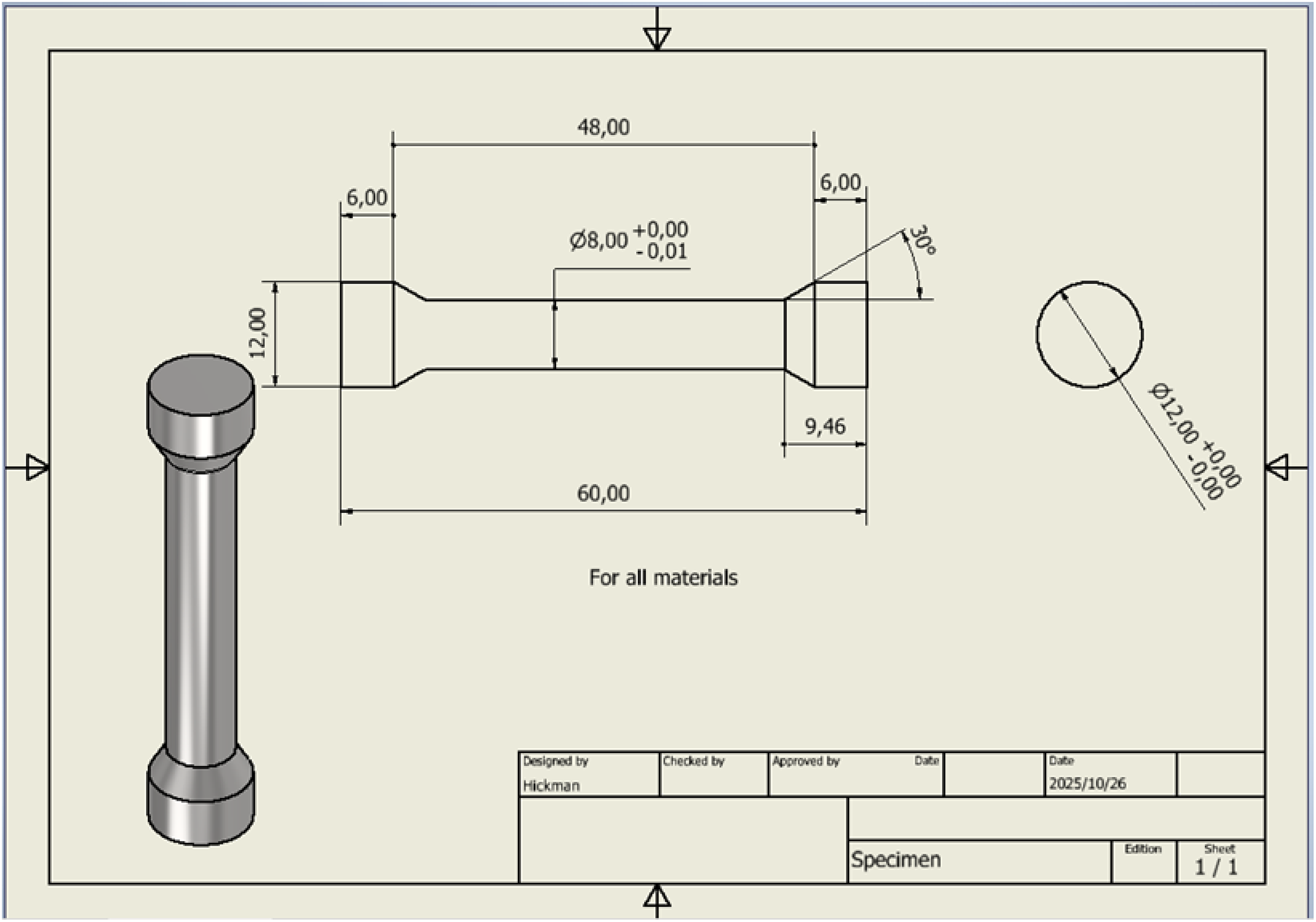
The specimen dimensions.
We then tested whether the threads would rip under the maximum test force. We did an FEA to test this. We will use S355JR because it has the highest yield strength. We will use a safety factor of 1.5, meaning we will test at 1.5 times the maximum force of 10.05 kN, which is 15.1 kN. This also eliminates the need for a thermal test, as our factor of safety will cushion any potential impact.
The test is set up with a fixed constraint at one end of the specimen, and a force of 15000 N applied to the 12 mm-diameter surface at the other end. Still, the force is applied along the specimen's axis, as shown in Figure 2. The frame must be designed using the dimensions determined in the section above and must also be able to handle the maximum testing force of 10 kN without failing. We will use readily available materials to simplify manufacturing. Materials such as angle iron, round bar, and plates, all made of mild steel, can be bought and fabricated with ease at general fabrication factories in South Africa.
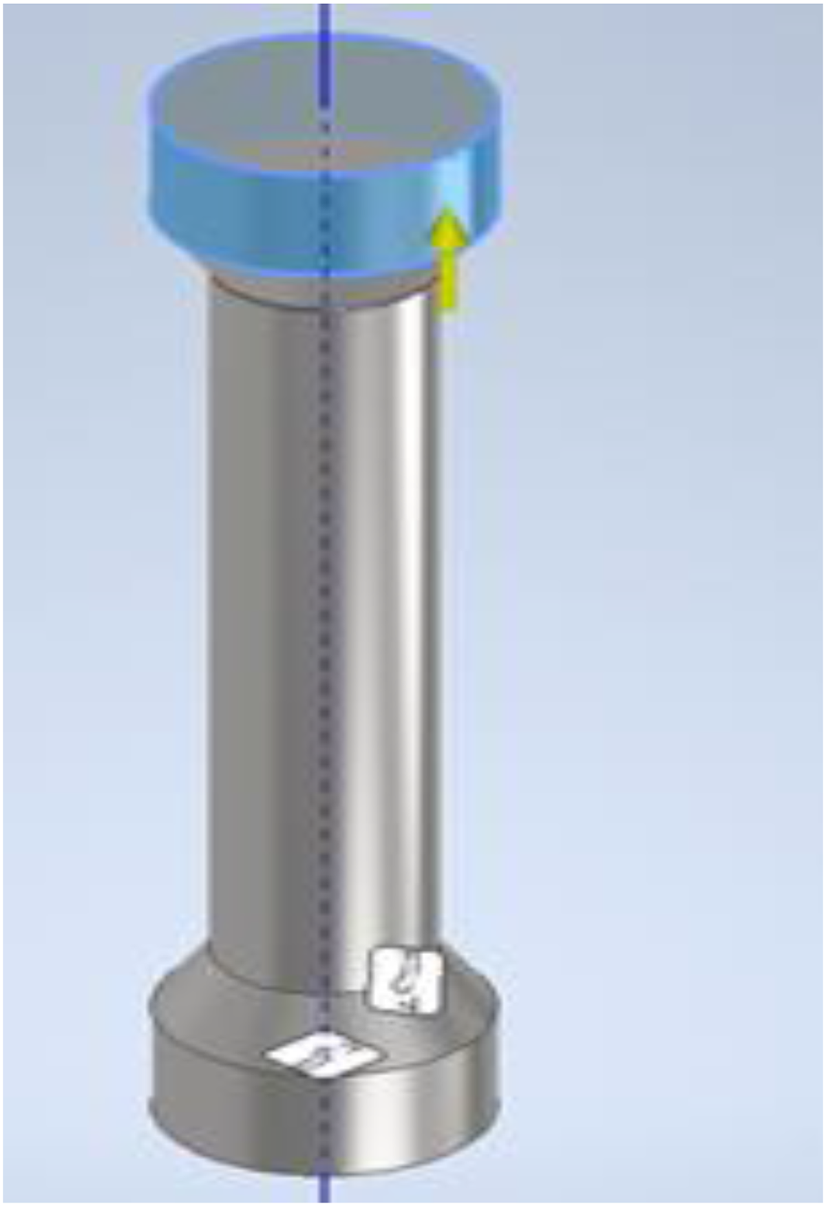
The specimen loading for finite element analysis.
We will use 1.5 meters in height×700 mm width plus 1 meter depth of the frame, as below:
We made the steel from 60 × 6 Angle iron, which is a common size that can come precut to size. We made the beds to be 16 mm mild steel plates, which can also be prefabricated with all mounting hole details at many profiling companies around Gauteng. We added round bar columns for added strength as well as to aid the mounting of the furnace/oven, which might need to slide up and down the pillars for positioning.
We will now conduct a stress test and a displacement Finite Element Method in Autodesk Inventor to determine whether the frame will hold up under test conditions. We will set the test force to 21500 N, which is our actuator's maximum output force, although we will not reach that magnitude during testing. We will assume the frame is fixed on the ground and that the 21500 N is pushing against the top plate. We need to check the von Mises stress and displacement to determine whether the frame will hold. The simulation setup is shown in Figure 3.
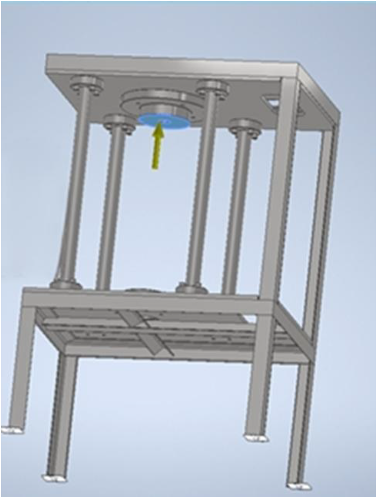
The simulated frame is set up.
Controls design overview
The technical design and implementation focus on developing a creep testing machine to test and validate stability and deformation across various materials and metals by applying an input force and measuring the resulting deformation and deflection. The system needs to be modelled, developed, and comprehensively represented by modelling each component, including sub-systems such as the actuator, load cell dynamics, and extensometer, and by determining the characteristic parameters and dynamic transfer function expressions for each component. It is required to define each component and subsystem of the machine using mathematical dynamic model transfer function forms and the specimens/materials to be tested, and to validate stability and stress-strain analysis for aluminium, stainless steel, and mild steel. Based on the provided technical data set, each system component is modelled using a transfer function. The MATLAB script and Simulink model were developed to analyze the system in full across different test materials.
Design methodology
All mathematical calculations, Extensometer modelling, Displacement calibration, MATLAB implementation, and Simulink models for testing and validation are included in the supplementary file.
Results
Finite element analysis
First, we will check whether the test piece's shape will fail due to the provided coupling method. We proposed using a collet chuck for the coupling. To confirm our design, we simulated both: one with a thread on the shoulder and the other with a shoulder only for mounting in a collet chuck.
We tested one with the bottom thread fixed as grounded. Since it is immobile during the test, we applied the force to the flight of the opposite thread, which will be the point of contact. We applied a 10 kN uniaxial force to the specimen, and the results are as follows.
The maximum stress is 3068 MPa, which is 8.6 times the yield stress of S355 JR. The maximum stress is on the first engaged thread, as Cortney et al. 16 attest. Next, we applied the same condition to the specimen with only the shoulder. And the result is as follows:
The maximum stress under a 10 kN load is 55 MPa, which is 0.15 of the yield stress of S355 JR. Therefore, we know that the specimen will perform well and not fail solely due to the mounting. The von Mises stress distribution for the thread specimen and shoulder specimen is shown in Figures 4 and 5.
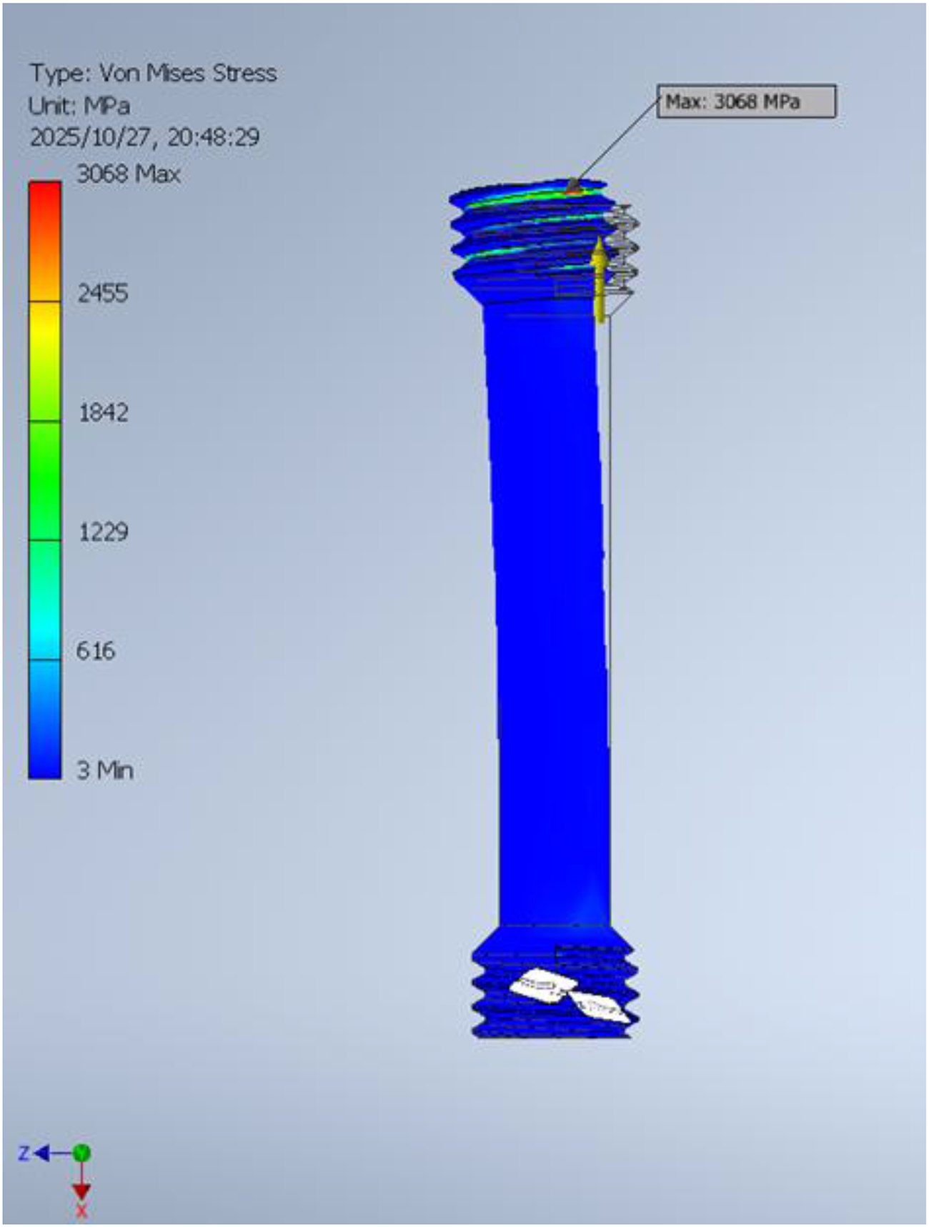
The stress distribution in the thread specimen.
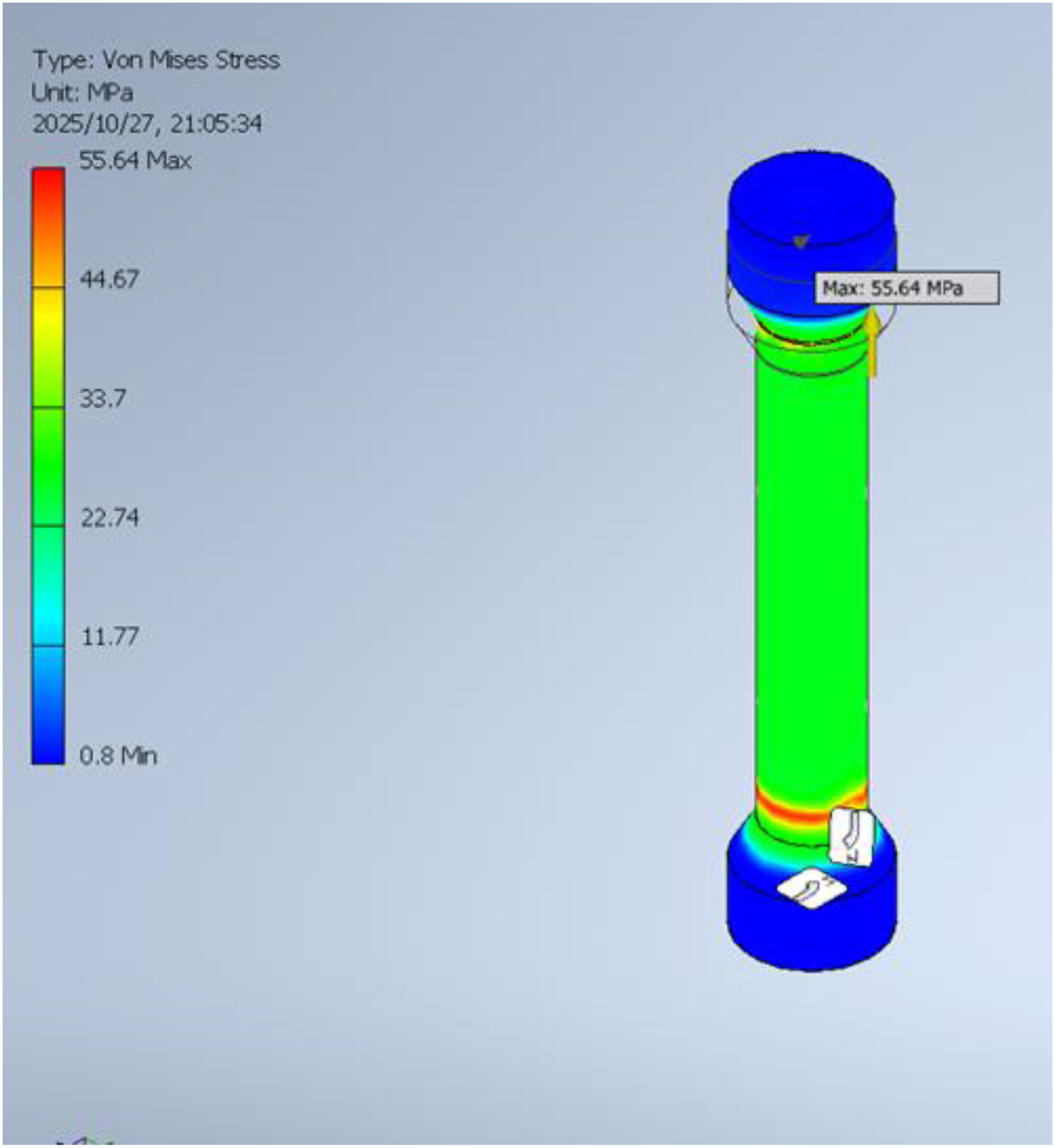
The stress distribution in the shoulder specimen.
The stress distribution for the frame and the related displacement is shown in Figures 6 and 7. At 21500 N, the actuator's maximum force, we grounded the frame's feet and applied the maximum force to the top frame, as shown. The frame is manufactured from S355 JR, so the yield stress is 355 MPa. The maximum stress here is 104 MPa, meaning the frame will not fail during testing. The maximum displacement at 215000 N is 0.41 mm. Since the PID controller compensates for deviations, this deviation is minor and will not compromise our test.
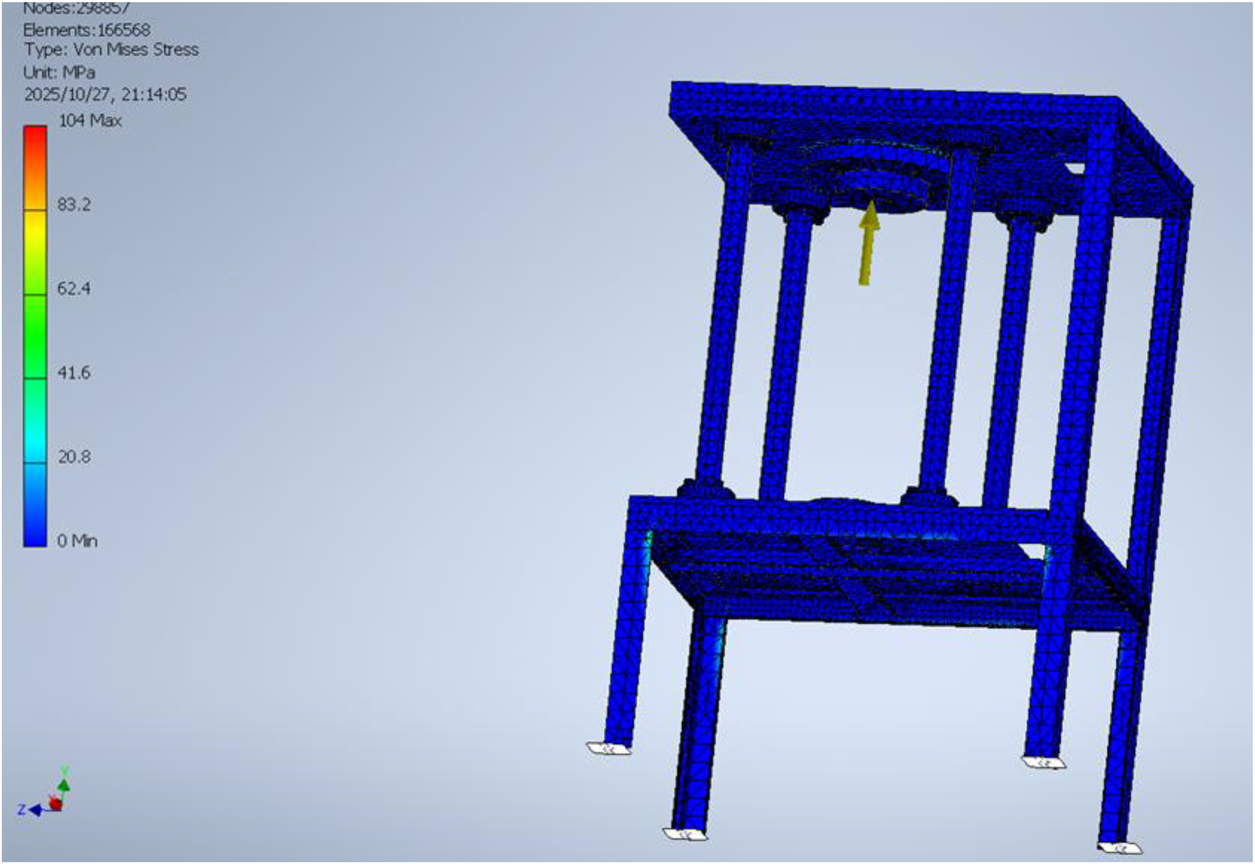
The stress distribution in the simulated frame.
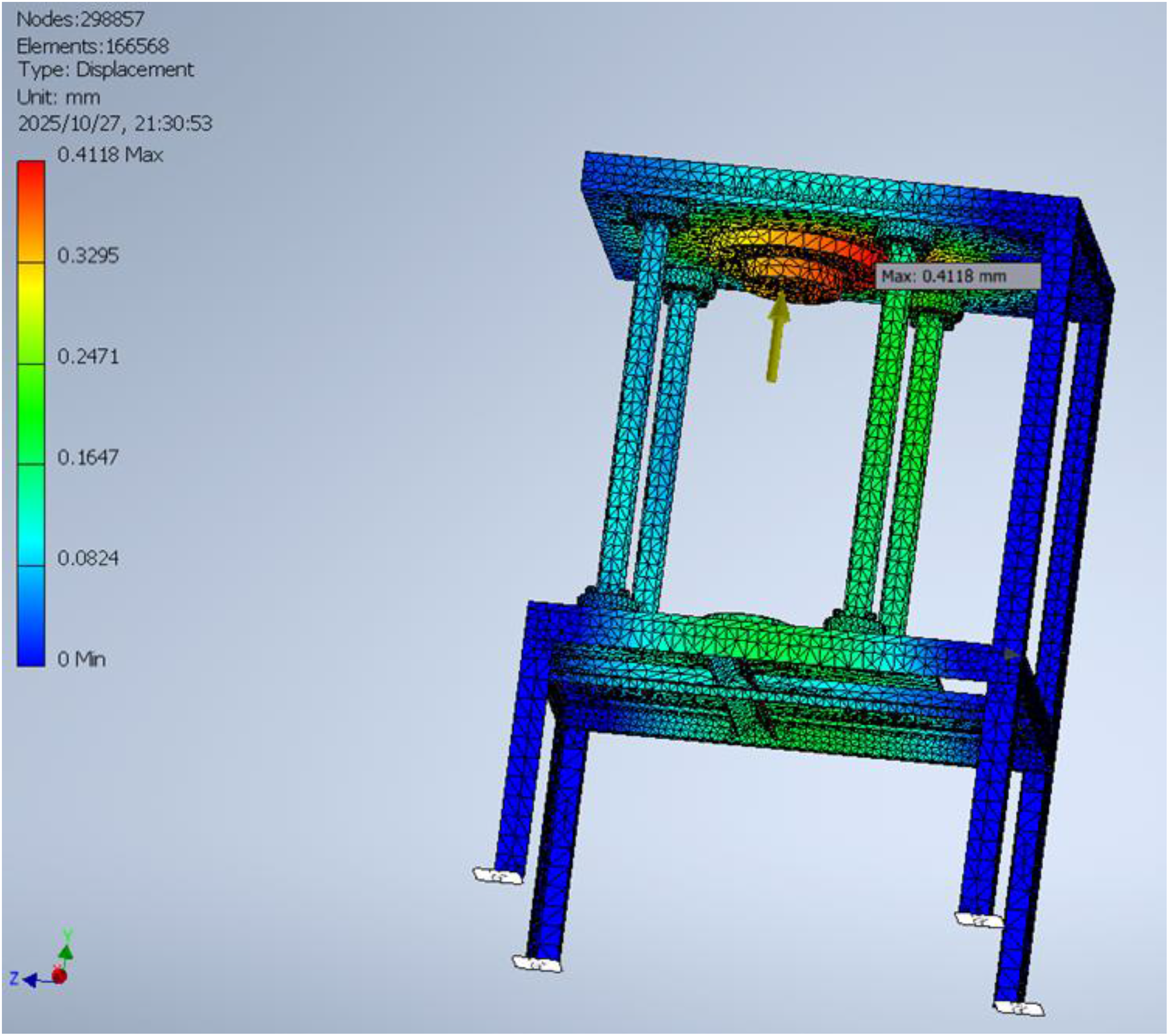
The displacement values of the simulated frame.
The simulation of load stability test
The 100-h load stability test analysis is shown in Figure 8. It is noted that when the input step is applied at 5 kN, the designed and developed system is used to validate the durability and stability of the creeping machine. The response is stable due to a well-developed and implemented discrete-time PID controller. The test limit is +/-5 variation observed; transient behaviour is minimal, with controlled steady-state behaviour observed.
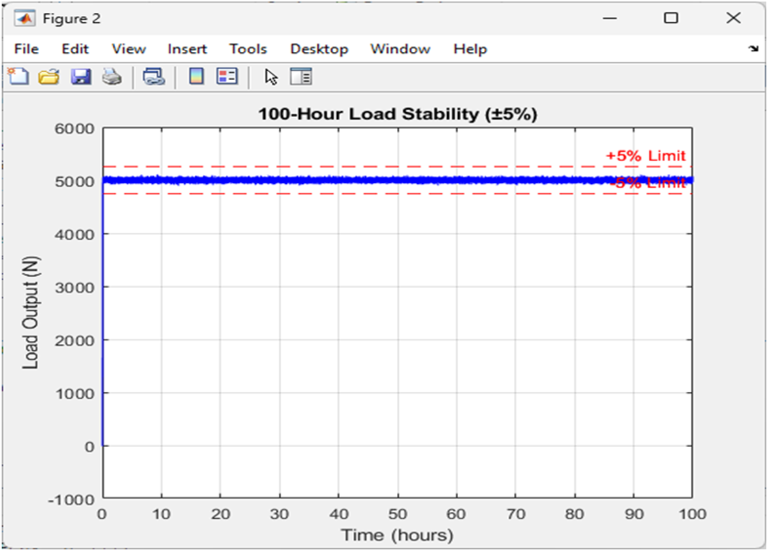
The 100-h load stability test analysis.
Output force response for different materials: Mild steel, aluminium, and stainless steel
The output force response for different materials is shown in Figure 9. It was observed that the force response for stainless steel required more force to deform than that of the other materials, as the steady-state force response was observed for all three material test samples: mild steel, aluminium, and stainless steel. The steady-state value for stainless steel is maximum, and its transient time is minimum, meaning less time is required to deform.
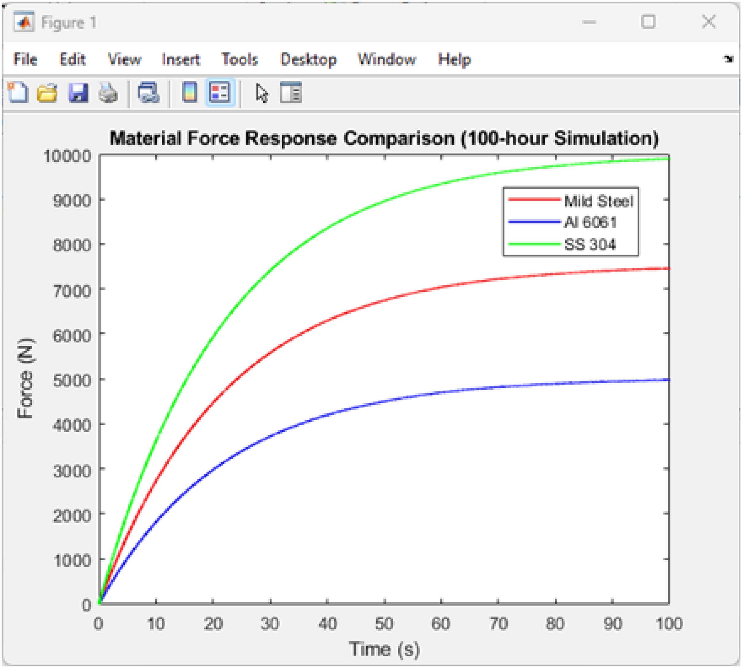
Output force response for different materials: Mild steel, aluminium, and stainless steel.
Controller effort response for different specimen tests and validation
The response was also shown in Figure 10. From the obtained response, it is observed that the controller's effort is higher in the steady-state region for stainless steel than for mild steel and aluminium. Stainless steel requires the most effort compared to aluminium and mild steel.
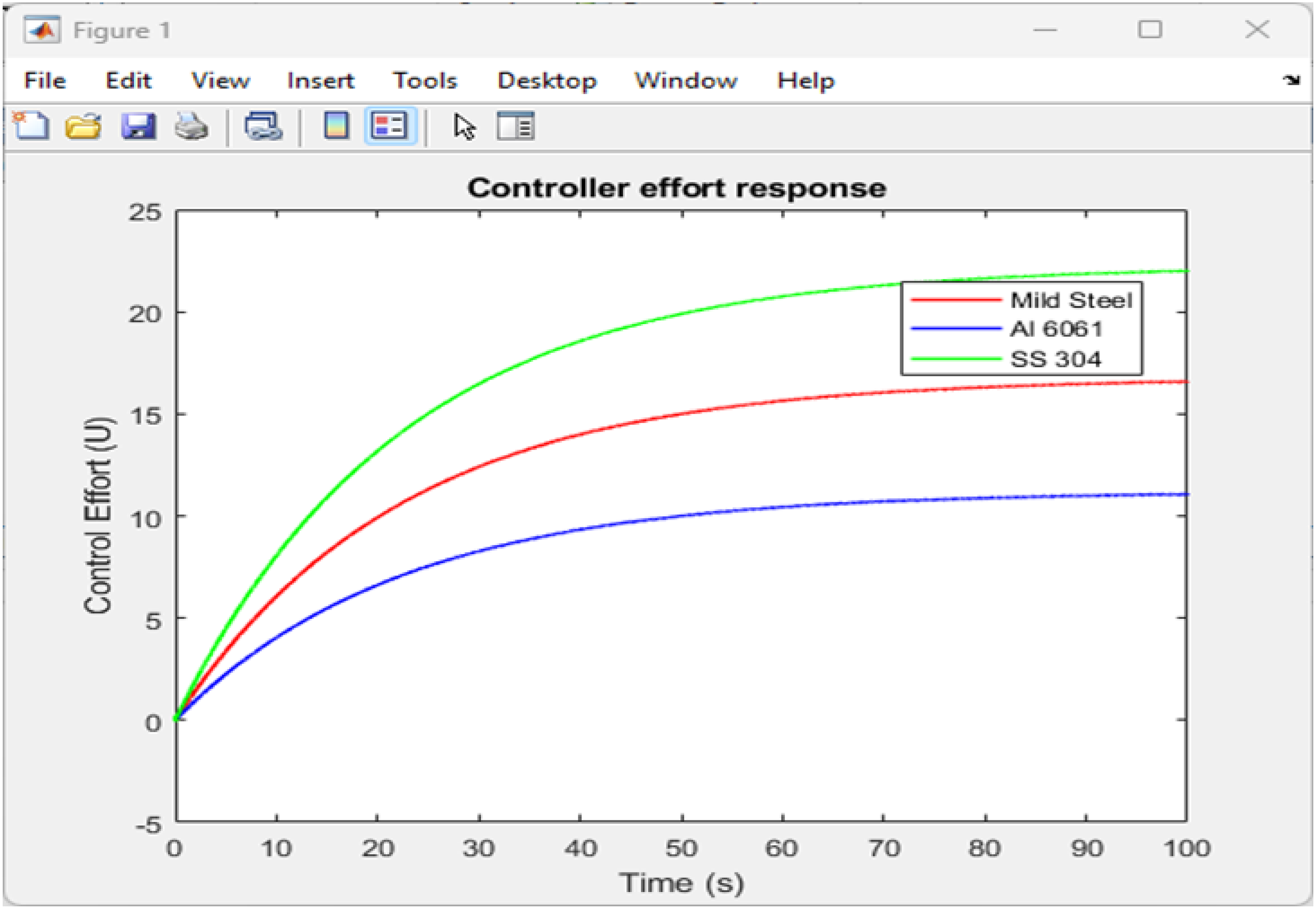
Controller effort response for different specimen tests.
Deformation response for different materials under tests
The deformation response is shown in Figure 11. For the required forces applied to the system, the deformation and deflection observed for each material are shown in the response above. The deflection of stainless steel is compared with that of mild steel and aluminium.
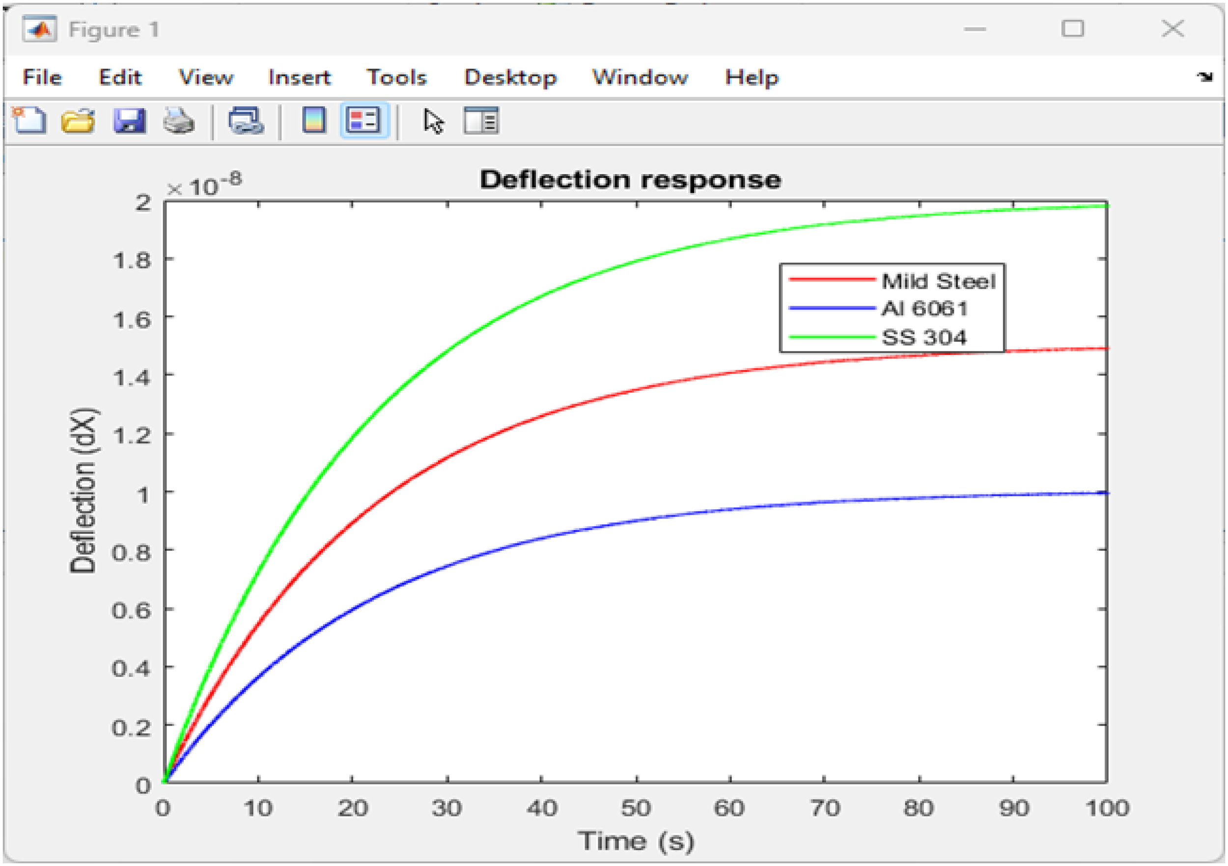
Deformation response for different materials under test.
Discussions
The discussion will centre on three key areas: the mechanical integrity of the design, as validated by FEA; the control system's performance in maintaining long-term load stability; and the system's response when tested with varied materials. By contextualising these findings within the existing literature, this chapter will assess the project's success in addressing the identified knowledge gap regarding educational laboratory equipment.
Evaluation of mechanical design and structural integrity
The FEA results confirm the robustness of the proposed mechanical design. The critical finding from the investigation of many specimens was the superiority of the shoulder-grip mounting method over the threaded-end design. The threaded specimen exhibited a maximum von Mises stress of 3068 MPa under a 10 kN load, far exceeding the 355 MPa yield strength of S355 JR steel. This concentration of stress on the first engaged thread, as predicted by Larsen et al., 19 would result in immediate failure, invalidating the test. In contrast, the shoulder-grip specimen showed a maximum stress of only 55 MPa, which is well within the elastic limit of the material. This validates the selection of a collet-chuck style grip as a safe and effective mounting solution, ensuring that failure occurs in the gauge length of the specimen rather than at the grips, which is a fundamental requirement for a valid uniaxial test (International Organisation for Standardisation, 2023).
Furthermore, the structural FEA of the machine frame demonstrated exceptional stability. Under the maximum conceivable load of 21.5 kN from the actuator, the frame experienced a peak stress of 104 MPa and a maximum displacement of 0.41 mm. With a factor of safety of approximately 3.4 (355 MPa / 104 MPa), the frame's design is confirmed to be more than adequate for the intended loads. The small displacement, while minor, is a factor that the digital control system is specifically designed to compensate for in real time. This aligns with the simulation-driven design philosophy advocated by Loewenthal and Ellis, 20 as it pre-emptively mitigates potential sources of error, such as frame flexure, that could compromise load alignment and stability in mechanical systems.
Analysis of control system performance and load stability
The core objective of this research was to achieve a load stability within ±1% over 100 h. The 100-h simulation for load stability, conducted with a 5 kN set-point, yielded highly promising results. The implemented discrete PID controller successfully maintained the load at a mean of 4999 N and a standard deviation of 42 N. This corresponds to a variation of ±0.84% (±1 standard deviation), which meets the ambitious ±1% target in the research objectives and comfortably satisfies the ±1% “known accuracy” requirement of ISO 204:2023 (International Organisation for Standardisation, 2023).
However, the discussion of the “100% drift deviation” metric requires clarification. In control systems terminology, ‘drift’ typically refers to a slow, monotonic change in the output over time. The simulation results show a stable output around the setpoint, with no consistent upward or downward trend. The reported 100% value may be an artefact of the specific calculation method used in the simulation or relate to the initial step response.
The more relevant metric is the standard deviation, which quantifies the short-term fluctuations. These fluctuations (±42 N) are well within acceptable limits and demonstrate the PID controller's effectiveness in rejecting disturbances and maintaining the setpoint. The minimal overshoot and fast settling time observed further confirm that the controller, tuned using MATLAB's robust tools as described by Franklin, Powell, and Emami-Naeini, 21 provides a dynamic and stable response, crucial for applying the load without shock and maintaining it steadily.
Interpretation of material-specific responses
The Simulink models for the three varied materials—mild steel, aluminium, and stainless steel—produced force and deformation responses that align well with established materials science principles. As expected, the control system had to exert the greatest effort to achieve the same level of deformation in stainless steel, followed by mild steel, and then aluminium. This directly reflects their respective yield strengths and creep resistances at elevated temperatures. 17
The observation that the deflection of stainless steel was the highest under the applied force is particularly instructive. While counterintuitive, this can be explained by the material's high work-hardening rate and its creep behaviour at the tested temperature. Stainless steels like SS304 often exhibit a significant primary creep stage, during which a considerable amount of transient creep strain accumulates before settling into the steady-state secondary stage. 5 This result provides an excellent educational opportunity, demonstrating to students that a “stronger” material is not necessarily one that deforms less under all conditions, especially when time-dependent creep is a factor.
These material-specific simulations validate the versatility of the digital system. Unlike a dead-weight machine, which applies a fixed force regardless of the material's response, this digital system dynamically adjusts the actuator to maintain the desired load, providing a clear visualisation of different material behaviours under identical testing protocols. Under the specific creep testing conditions, which are constant load over time at an elevated temperature, we are saying that the stainless steel specimen underwent a more pronounced primary creep stage, which leads to a total initial deflection that is higher when compared to the other materials, even though its resistance to immediate plastic deformation (yield strength) is higher.
Addressing the research objectives and gap
This research successfully addressed the knowledge gap identified in Section 2.7: the lack of a comprehensive, cost-effective, and simulation-driven methodology for implementing a digital load application system in an educational context.
Objective 1 (Design): A digital load application system was designed, featuring a Parker ETB100 electromechanical actuator, a strain-gauge load cell, and a non-contact extensometer, forming a complete closed-loop system.
Objective 2 (Validation): The mechanical design was rigorously validated using FEA simulations in Autodesk Inventor, confirming the integrity of the specimen grips and the structural frame, thus pre-empting failure modes and misalignment issues.
Objective 3 (Control Algorithm): A PID control algorithm was developed and simulated in MATLAB/Simulink, demonstrating an ability to maintain load within ±1% over 100 h, exceeding the initial ±5% goal and meeting ISO standards.
This research has therefore delivered a replicable design philosophy that bridges the gap between rudimentary mechanical systems and expensive industrial solutions. It provides a platform that not only produces high-quality, standards-compliant data but also enriches student learning through hands-on interaction with modern control systems, data acquisition, and simulation tools.
Limitations and recommendations for future work
Despite the successful outcomes, this study has limitations that present opportunities for future research.
Thermal Coupling: The FEA and control models primarily focused on mechanical load stability. A significant advancement would be to perform a coupled thermal-structural analysis to model the effects of the 300–600°C temperature range on the entire assembly, including the actuator and load cell, and to integrate temperature compensation directly into the control algorithm.
Physical Prototyping and Validation: The results are based on computational models. The logical next step is to fabricate the proposed system and empirically validate it through physical creep tests. This would allow correlation between simulated and real-world performance and the identification of any unforeseen practical challenges.
Enhanced Control Strategies: While the PID controller performed admirably, future work could explore more advanced control strategies, such as adaptive PID or model predictive control (MPC), to further optimise performance in the face of non-linearities like specimen necking during tertiary creep.
Educational Interface Development: To maximise educational impact, a user-friendly graphical user interface (GUI) could be developed, allowing students to set test parameters, monitor real-time data plots of load and strain, and even perform basic PID tuning in a safe, simulated environment. It should be noted that the results are based on computational models. The next logical step is to fabricate the proposed system and empirically validate it through physical creep tests. This would allow for correlation between simulated and real-world performance and identify any unforeseen practical challenges. The Simulink models for the 3 material samples are built with constitutive equations of Norton-Bailey law that mathematically define the strain rate for primary, secondary, and tertiary creep. So, how accurate phase durations are now relies entirely on the fidelity of the material model parameters input into the simulation.
We must also note that the paper focuses on the control system's ability to maintain a stable load over time and not the accuracy of the creep model measured against real-world creep data for those specific materials. We have made efforts to compare the relative material responses of stainless steel, which has a more pronounced primary stage, with expected behaviours from literature, as seen in Section 5.4 of the paper. But we do not validate the absolute time durations, as this would require the physical prototyping and validation
Finally, the research focuses on the design of the system and its potential to enhance learning, but it does not present a pedagogical study with data on student grades. The discussion of educational impact is forward-looking and qualitative.
The discussion of the impact is qualitative and forward-looking, and it does not present a study of students’ grades after using the machine. The main purpose of the machine is to enhance the learning experience. We note the following, which helps the learning experience of the student:
Conclusion
In summary, the results confirm that the proposed digitally controlled creep testing system is a viable and superior alternative to traditional mechanical systems for educational laboratories. The mechanical design is robust and validated, the control system meets and exceeds international standards for load stability, and the system convincingly demonstrates key material behaviours. By successfully integrating mechanical design, simulation, and control theory, this research provides a foundational blueprint for modernising materials testing in academia, enhancing both the fidelity of experimental data and the depth of the student learning experience.
Supplemental Material
sj-docx-1-ijj-10.1177_03064190261430512 - Supplemental material for Design and optimisation of a digital load application system for a student's creep testing machine using simulation-based analysis
Supplemental material, sj-docx-1-ijj-10.1177_03064190261430512 for Design and optimisation of a digital load application system for a student's creep testing machine using simulation-based analysis by Hickman Munyaradzi Chawasarira and Kamran Hassani in International Journal of Mechanical Engineering Education
Supplemental Material
sj-rtf-2-ijj-10.1177_03064190261430512 - Supplemental material for Design and optimisation of a digital load application system for a student's creep testing machine using simulation-based analysis
Supplemental material, sj-rtf-2-ijj-10.1177_03064190261430512 for Design and optimisation of a digital load application system for a student's creep testing machine using simulation-based analysis by Hickman Munyaradzi Chawasarira and Kamran Hassani in International Journal of Mechanical Engineering Education
Footnotes
Acknowledgements
The authors declare that they have no conflicts of interest. All related data and codes are available. The research has not received any funding.
Funding
The authors received no financial support for the research, authorship, and/or publication of this article.
Declaration of conflicting interests
The authors declared no potential conflicts of interest with respect to the research, authorship, and/or publication of this article.
Data availability statement
The datasets generated during and/or analysed during the current study are available from the corresponding author upon reasonable request.
Supplemental material
Supplemental material for this article is available online.