
Abstract
Sustainability is increasingly central to engineering education, with aquaponic systems offering a practical model of sustainable practice. Aquaponics system integrates fish and plant cultivation in a symbiotic environment, requiring a broad spectrum of engineering competencies, including computer-aided design (CAD), electronics, and embedded control systems. This paper presents the design and implementation of a laboratory-scale aquaponic system as a pedagogical tool for teaching mechanical and interdisciplinary engineering concepts. Students begin with ergonomic design considerations, incorporating features such as nutrient dispensers, modular plant beds, and a rack-and-pinion mechanism for irrigation. The design process evolves from hand-drawn sketches to detailed CAD models, which are subsequently realised through 3D printing. The completed system is tested and refined to ensure functionality. To demonstrate its educational value, three experimental case studies are presented, each aligned with core mechanical engineering topics. A mapping of these learning outcomes to standard mechanical engineering modules is provided, alongside reflections on student engagement and learning. Beyond technical skill development, the project fosters an appreciation for sustainable engineering solutions in agriculture, offering a hands-on, interdisciplinary learning experience.
Keywords
Introduction
A key attribute that engineering students should develop through education is the ability to think critically and creatively,1,2 as these skills are essential for contributing to global societal development. 3 This study aims to facilitate this by demonstrating a methodology for developing, designing, and experimenting with a practical project to provide relevant experiential learning Pamungkas et al., 4 and Gadola and Chindamo 5 in the real-world context of aquaponics.
Aquaponics is an agricultural practice that integrates the symbiotic cultivation of aquatic organisms and plants. 6 It combines recirculating aquaculture–the farming of fish with hydroponics, where plants grow. 7 In an aquaponic system, nutrient-rich effluent from fish excretion is channelled to plants, providing essential nutrients, while the plants, in turn, filter and improve water quality by removing excess waste. 8 This improvement in water quality enables safe recirculation back to the fish, reducing overall water consumption and minimising environmental discharge, such as fertiliser runoff. 9 Aquaponics is widely regarded as a sustainable agricultural method due to its reliance on natural biological cycles between fish, plants, and water resources. 9 However, despite its potential, aquaponic systems are often considered economically unviable, 10 limiting their widespread adoption. To fully harness the potential of aquaponics, education plays a crucial role in fostering student interest and innovation, potentially leading to future advancements that could make aquaponics a mainstream sustainable agricultural practice.
The objectives of this paper are twofold: (i) to demonstrate the versatility of a lab-scale aquaponic system as a tool for teaching mechanical engineering with a focus on sustainability, and (ii) to develop an educational resource that effectively engages students in learning about aquaponics. These two objectives align with the principles of open-lab activity design, which seeks to foster curiosity, enjoyment, and interest by engaging students in a stimulating and exploratory learning environment. 11 The primary stakeholders for this study are educators in secondary schools and universities who seek to integrate aquaponics into STEM education. The concept of using aquaponic systems as teaching tools is not new; previous studies have explored their effectiveness in teaching sustainability to students across various age groups.12,13
Given the multidisciplinary nature of aquaponics, 6 the system offers flexibility in its implementation across a range of subjects and modules, making it a valuable resource for educators. To meet stakeholder requirements, the system must be appropriately sized for educational environments such as laboratories and classrooms. It should be compact and lightweight for easy transportation, assembly, and disassembly. Furthermore, the project must be developed within a set budget, as financial constraints introduce an additional challenge that fosters problem-solving skills–an important aspect of engineering education. Additionally, cost considerations reflect the broader aim of making aquaponics commercially viable.
This educational lab-scale aquaponic system is based on a project undertaken by the first and second authors as part of their final-year individual projects for the Bachelor of Mechanical Engineering degree programme at the University of Warwick, United Kindgom. The paper also highlights the relevant modules from the Mechanical Engineering curriculum that contribute to the development of this educational resource for aquaponics.
System design and development
The aquaponic system was developed within a budget of Great Britain Pound, GBP 200 and a timeframe of 24 weeks. Working within these constraints required students to adopt a creative and innovative approach, balancing complexity and simplicity in the final system design. Three key design aspects are discussed in this study: the design of the main housing components, the design of the nutrient dispenser, and the design of the embedded control system incorporating a soil moisture sensor. As a note, due to logistical constraints, live fish were not included in the project. Instead, alternative experiments were conducted to simulate the role of fish within the aquaponic system. Additionally, to demonstrate
Main housing components for fish and plant
Aquaponic systems can generally be categorised into three types: media-based, nutrient film technique, and deep water culture (or raft system).14,15 The primary distinction among these systems lies in how nutrients are delivered from the fish tank to the plants. In this study, a media-based system was selected due to its low-cost setup, ease of operation, and suitability for beginners in aquaponics. 15
A media-based aquaponic system consists of a grow bed for plants and a tank for fish, with water continuously circulated between the two via a pump. In this design, two containers are used: one serving as the grow bed for the plants and the other as the fish tank. These containers are stacked vertically, with the plant container positioned above the fish tank.
In the lower container, a submersible 9 V DC pump is installed to facilitate water recirculation. The pump is connected to a 0.7 cm diameter pipe to ensure an adequate water supply to the upper container, where the plants are located. The pump serves two primary functions within the aquaponic system: (i) facilitates the diffusion of nutrients from fish excretion to the plants, and (ii) irrigates the plants. The pump is controlled using an Arduino Uno, a widely used microcontroller in the education sector for teaching embedded control systems. Programming is carried out using the Arduino Integrated Development Environment (IDE) software, 16 which provides a text editor for writing code and a platform for uploading code to interact with the hardware.
An initial schematic of the media-based aquaponic system is presented in Figure 1. Several issues were identified in the initial design. Firstly, managing excess water flow from the top container was challenging. The initial approach involved drilling holes at the bottom of the container; however, this resulted in rapid drainage, requiring the pump to remain constantly active to maintain a continuous water supply to the plants. Secondly, structural stability was a concern, as the initial design simply placed the plant container on top of the fish container without additional support. Thirdly, securing the plant grow bed proved problematic, as the initial design used a floating plant raft that lacked stability and tended to shift with the water flow.
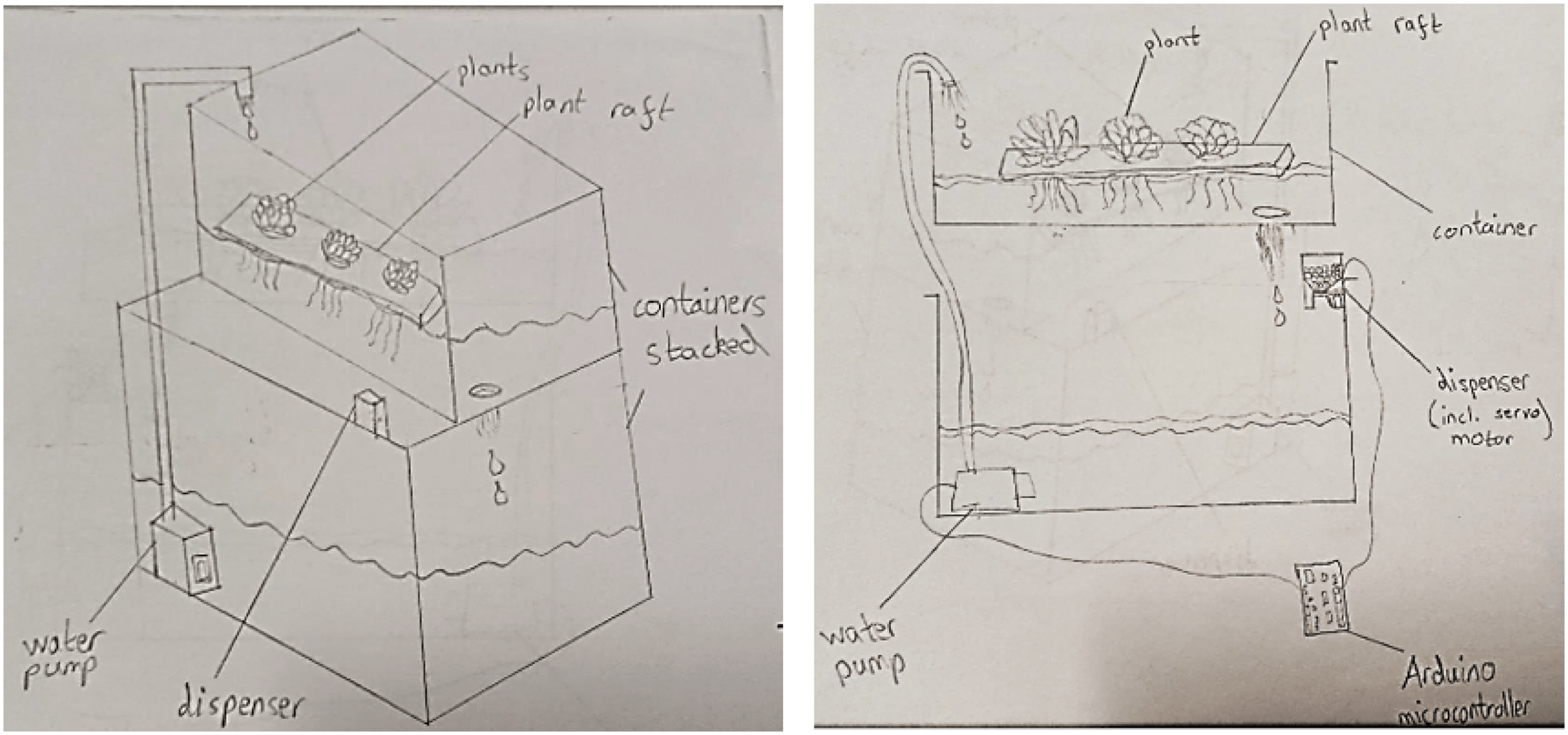
Initial sketch of the media-based aquaponic system.
Following several iterations to address these issues, the final design is shown in Figure 2. Firstly, to manage excess water flow, a drainage hole was positioned on the side of the plant container rather than at the bottom. This configuration ensures continuous water recycling between the two containers, maintaining an appropriate water level in the plant compartment and preventing overwatering. Secondly, to improve structural stability, two containers of different sizes were used, with the smaller plant container placed on top of the larger fish tank. Wooden supports were incorporated to enhance overall stability. Thirdly, instead of a floating plant grow bed, nursery cups containing grow medium were used. These were securely fitted within custom-made holders in the top container, ensuring stability and efficient nutrient absorption.
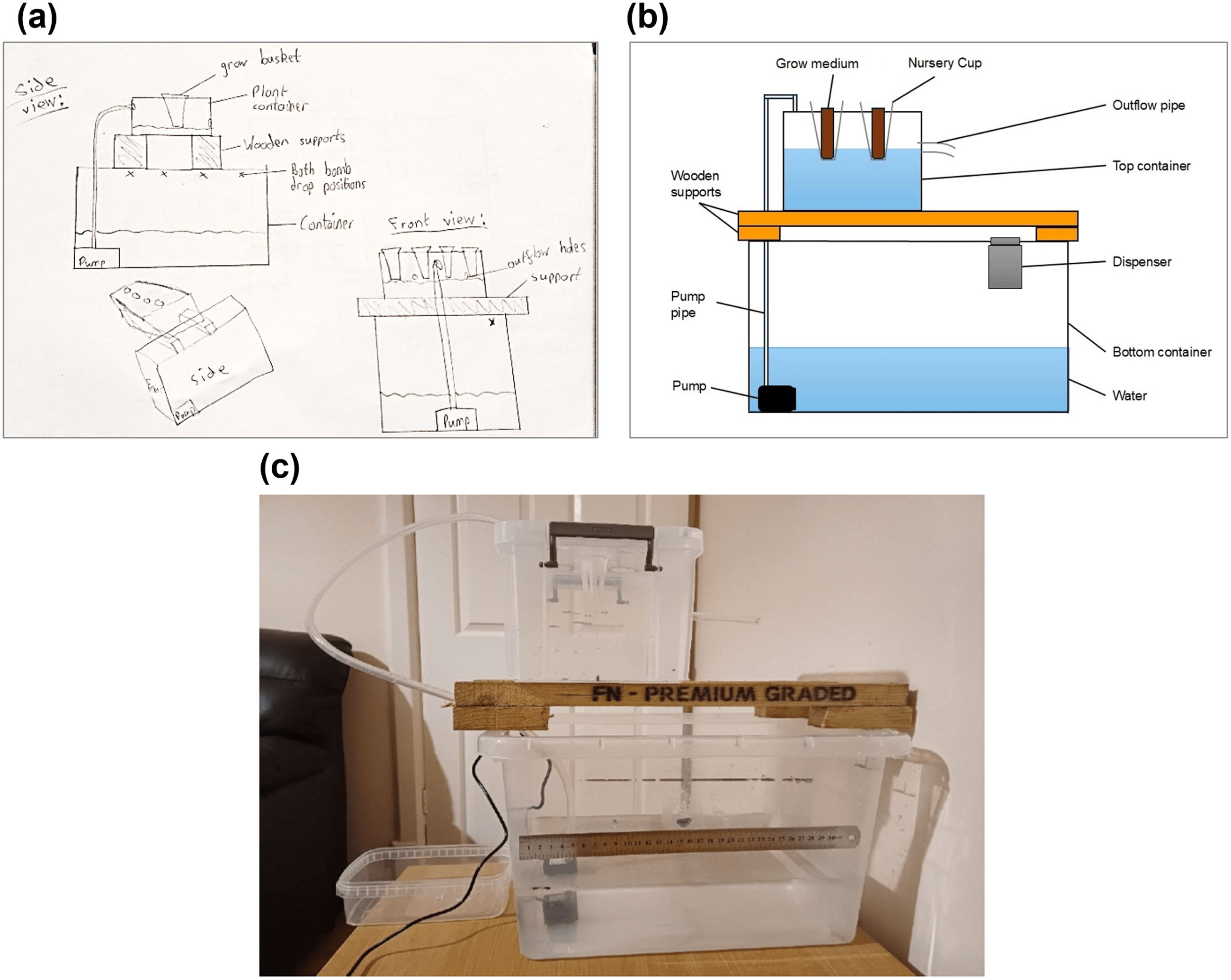
Final design the media-based aquaponic system. (a) Final sketch (b) Schematic drawing (c) Final prototype.
Nutrient dispenser
To simulate fish excretion, a nutrient pellet dispenser is incorporated into the system, with consideration given to automating this process. While fish waste is not typically regulated in a real aquaponic system, this provided an opportunity for students to undertake a mechanical design task by developing the dispenser. With the primary housing components for the fish and plants finalised, their dimensions can now be measured to create a 3D model in Fusion 360, 17 enabling the design of the dispenser to be attached to the fish tank.
Figure 3 illustrates the overall dispenser design process, from CAD modelling to the final prototype. The dispenser components were 3D-printed using the 3D printing facilities available at the School of Engineering, University of Warwick. Figure 3(a) presents the CAD model, detailing how the dispenser is mounted onto the fish tank. A two-part design was selected: the top section (yellow) serves as the nutrient pellet container and is secured to the fish tank using a hook, while the bottom section (grey) houses the servo motor. A 3D-printed rotating disc is attached to the servo motor, allowing controlled opening and closing of the dispenser (Figures 3(e) and (f)). The inclusion of a hook mechanism (Figure 3(g)) enables horizontal sliding of the dispenser, replicating the random distribution of fish waste in a natural environment.
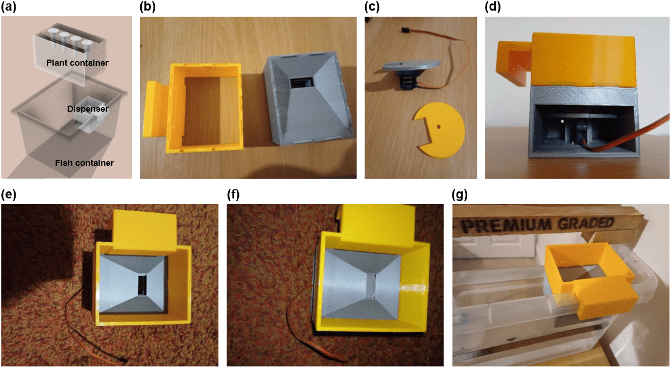
Nutrient dispenser design. (a) CAD drawing (b) 3D printed dispenser (c) Servo motor with 3D printed rotating disc (d) Dispenser incorporating the servo motor (e) Dispenser in ‘OPEN’ position (f) Dispenser in ‘CLOSE’ position (g) Dispenser attached to the fish tank.
Soil moisture sensor for embedded control system
An embedded control system is crucial in an aquaponic system to establish and maintain a controlled environment where both plants and fish can thrive. This study focuses on embedded control for plant irrigation based on soil moisture levels, employing the FC-28 Soil Moisture Sensor with an LM393 Comparator Chip. 18 Soil resistance is measured by applying a current of 35 mA across the electrode probes. As soil moisture content increases, electrical conductivity improves, resulting in lower resistance to current flow. The sensor outputs values ranging from 0 to 1023, with higher values indicating greater soil moisture content. Based on these detected moisture levels, the control system activates electromechanical components to implement relevant control actions–specifically, lifting or lowering the plant tray lid to optimise irrigation. There are several existing literature that provide a range of the classifications. In Ref. Abdullah and Mazalan, 19 the authors categorised the value between 0 to 610 as ‘dry soil’, 610 to 970 as ‘moist soil’, and 971 to 1023 as ‘wet soil’. In contrast, the same soil moisture sensor used in a project done on Instructables, which is an open-source website, 20 classified the value between 0 to 300 as ‘dry soil’, 300 to 700 as ‘moist soil’, and 700 to 950 as ‘submerged in water’. While these two studies provide different ranges of values for soil moisture levels, they offer a useful reference for calibrating the soil moisture sensor to our specific soil conditions.
Irrigation mechanism for plant
Initially, drip irrigation was considered for watering the plant when the soil moisture sensor detected ‘dry’ values. However, testing revealed that the pump produced an excessively high flow rate, submerging the soil in the nursery cup within seconds. This necessitated the development of an alternative method to regulate the flow rate and prevent overwatering. As the pump did not support variable flow rate control, a mechanical solution was implemented (Figure 4). A small slit was cut near the end of the rubber flow tube, serving as the new water exit point. The original opening was then sealed using a putty-like reusable adhesive (sticky tack), while cotton pads were wrapped around the slit to absorb excess pressure and reduce velocity, ensuring a gentler and more controlled water release.
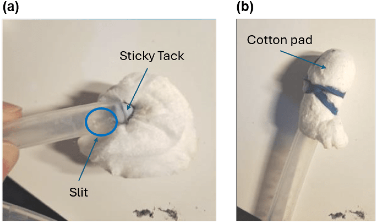
Mechanical method for controlling water flow. (a) Small slit is cut near the end of the rubber flow tube with stick tack sealing the original flow outlet (b) Cotton pads were use to seal the tube providing a gentler water release.
Several issues were identified during testing of the drip irrigation mechanism, including the limited number of nursery cups that could be watered simultaneously and the unreliable flow rate due to the unpredictable absorption capacity of the cotton. In light of these challenges, an alternative irrigation method was required, leading to the adoption of a ‘lifting and lowering’ mechanism.
Three candidate mechanisms were considered, as shown in Figure 5. In the tilting rack mechanism (Figure 5(a)), the plant container is lifted and lowered by tilting it at a specific angle. To ensure that the nursery cups remain upright, an additional rotation mechanism, comprising cylindrical rods passing through the cups, was incorporated. However, a key drawback of this design is the difficulty in achieving the optimal tilting angle to ensure that all nursery cups receive an equal amount of water. The direct lifting mechanism using a linear actuator (Figure 5(b)) employs linear push-pull solenoid valves to extend and retract the plant container. However, a major drawback of this design is the sudden jerking motion experienced by the plant container due to the high acceleration of the plunger during the extension and retraction process. The direct lifting mechanism using a rack and pinion system (Figure 5(c)) mitigates the jerking effect observed in the linear actuator design by employing a servo motor rotating the rack and pinion to facilitate smoother motion. However, this approach introduces the potential risk of slippage and misalignment of the pinion gears, which could compromise the precision of the lifting mechanism.
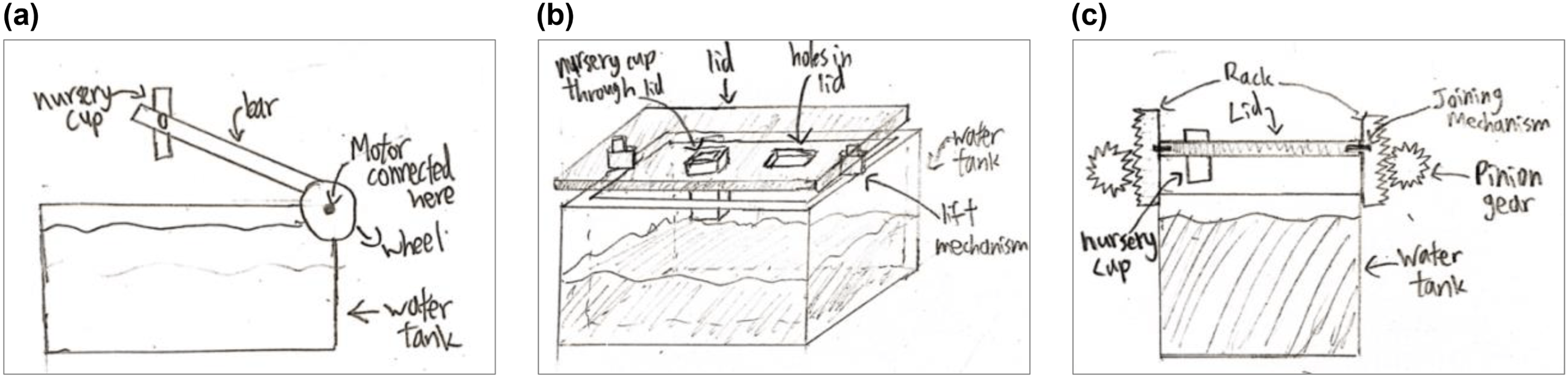
Different sketches of ‘lifting and lowering‘ mechanism. (a) Tilting rack (b) Direct lifting using linear actuator (c) Direct lifting using rack and pinion.
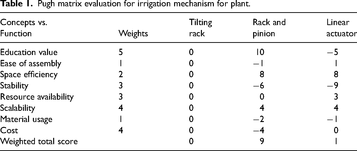
The advantages and disadvantages of each mechanism were evaluated using a Pugh Matrix. 21 The Pugh Matrix is a systematic decision-making tool used to evaluate and compare multiple design concepts or alternatives against a defined set of criteria. It is typically presented as a matrix, in which each cell indicates the relative performance of a candidate design in comparison to a baseline–commonly represented by zero. Through the structured assessment of the advantages and disadvantages of each option, the Pugh Matrix supports the identification of the most appropriate design solution. Here, factors such as educational value, ease of assembly, space efficiency, stability, resource availability, scalability, material usage, and cost were considered. The tilting rack mechanism was used as the baseline for comparison. A five-point rating scale was employed, where -2 indicates “much worse”, -1 “worse”, 0 “same”, +1 “better” and +2 “much better” relative to the baseline. The scores presented Table 1 reflect values that have already been multiplied by their corresponding weighting factors. Based on this assessment, the direct lifting mechanism using a rack and pinion was selected as the final design.
Pugh matrix evaluation for irrigation mechanism for plant.
Rack and pinion design
The first step involved measuring the dimensions of the plant container and tray lid, prior modelling them in AutoDesk Fusion 360. 17 To account for measurement variations and printing uncertainties, a minimum tolerance of 1 mm was included, with larger tolerances for areas with greater uncertainty. Additionally, a simple 3D model of the SM-S2309S servo motor was constructed. A spur gear model was generated using the Add-In function in Fusion 360 where the gear thickness was initially set to 14 mm, allowing for later adjustments if necessary. The servo motor includes a set of plastic mounts designed to fit onto its output shaft. To secure the spur gear to these mounts, a set of holes matching those on the mounts was incorporated into the gear. Given the small diameters of these holes (less than 1 mm), metal wires will be used to fasten the gears to the mounts, ensuring a secure connection. The 3D model of the servo motor and the spur gear alongside the final product is shown in Figure 6(a).
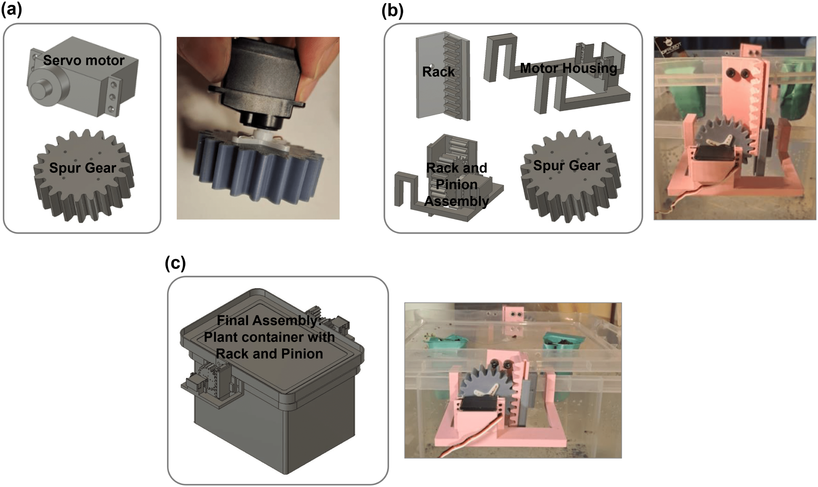
Construction and assembly of rack and pinion system. (a) 3D model of servo motor and spur gear and the final product (b) 3D model of rack and pinion and the final product (c) 3D model of the final assembly of the rack and pinion on the plant container and the final product.
Following the gear deisgn, the rack was created using the teeth of the gear as a reference to ensure proper meshing with the rack teeth. The rack was initially designed to a length of 68 mm to provide additional clearance between the gear teeth and the top and bottom edges of the rack at positions of maximum displacement. An M4 bolt size was selected as the drillable space on the side of the tray lid has a height of 11 mm (out of the total 19 mm). To ensure adequate clearance, the hole diameter was set to 4.9 mm, leaving approximately 3 mm of material above and below the hole. The mounting hole on the rack was positioned approximately 24 mm from the top, ensuring that, assuming the gear was at a similar height, approximately 38 mm of rack remained below the hole to accommodate a 30 mm lift. The servo motor housing was then be designed based on the rack and pinion arrangement, as well as the container’s wall thickness. The corresponding 3D models and final product are shown in Figure 6(b), while Figure 6(c) presents the finalised 3D component designs alongside the fully assembled system.
In structural and design engineering, Finite Element Analysis (FEA) is widely employed to evaluate the response and structural integrity of components under various loading and boundary conditions. The development of a three-dimensional model facilitated the application of FEA to simulate the behaviour of the design and identify potential failure points. Figure 7 presents the von Mises stress distribution 22 within the rack and pinion mechanism when subjected to the combined weight of the tray lid, nursery cup, and soil.
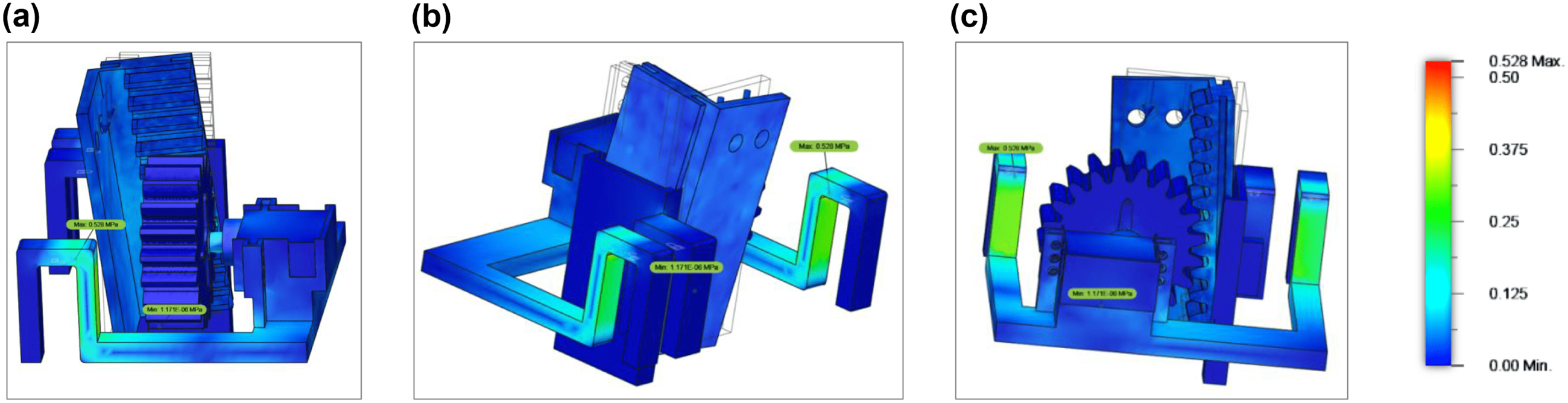
Finite element analysis of the rack and pinion system. (a) Side view simulation (b) Isometric view simulation (c) Back view simulation.
Von Mises stress is a commonly used output in FEA simulations, providing a scalar representation of the stress state that helps to visualise stress distribution and pinpoint areas susceptible to yielding or failure. Under complex, three-dimensional loading scenarios, von Mises stress offers a theoretical scalar value that encapsulates the multidimensional stress tensor at each point in the structure. It is derived from the distortion energy theory, which posits that material failure occurs when the distortion energy reaches a critical threshold. Although not a physical stress in itself, von Mises stress amalgamates multiple stress components into a single value, enabling straightforward comparison with the material’s yield strength.
It is essential for engineering students to grasp and apply these concepts in their design projects to ensure structural reliability and safety. The straightforward yet effective approach of comparing von Mises stress values obtained through FEA with the material’s yield strength allows even novice engineers to validate their designs with confidence.
As shown in Figure 7, highest stress concentrations occur at the arms that fit onto the container wall, necessitating reinforcement. The introduction of fillets at the corners helps distribute forces more evenly. Another critical stress point is the connection between the servo motor and the plastic mount (Figure 7(a)), which can be strengthened with relevant adhesives technologies. 23 The weight of the tray lid acts on the rack through the bolt connections, generating a moment due to its L-shape, which causes the rack to rotate and deform towards the container. The interaction between the rack and the inner guide rail walls may generate friction forces, potentially reducing the smoothness of the mechanism. However, it is important to note that the simulation visually amplifies deformations and displacements beyond their actual values. Additionally, the highest stress point with 0.528 MPa is signficantly lower than polylactic acid (PLA) yield strength of 26.08 MPa. 24 Hence, it can be concluded that the components will not fail during operation.
Electronics design for pump and dispenser
The electronic components used in this setup include a 9 V DC immersible pump, a servo motor (for the nutrient dispenser), and an Arduino microcontroller board. All these components are part of the DFROBOT ‘EcoDuino – An Auto Planting Kit’. 25 The kit includes a battery holder for six 1.5V AA batteries, providing the total required 9 V for the pump to operate at its maximum power. A DC adaptor is used to connect the battery holder to the Arduino board. The microcontroller board facilitates the connection of the electronic components to the power supply.
The USB connection on the Arduino board enables communication with a computer for uploading code written in the Arduino IDE.
16
Figure 8(a) illustrates the Arduino board with all components connected, enclosed in a protective casing to safeguard against water exposure. Figure 8(b) presents the wiring connections on the board. The pump cable consists of two wires, with the brown and blue wires connected to the ‘
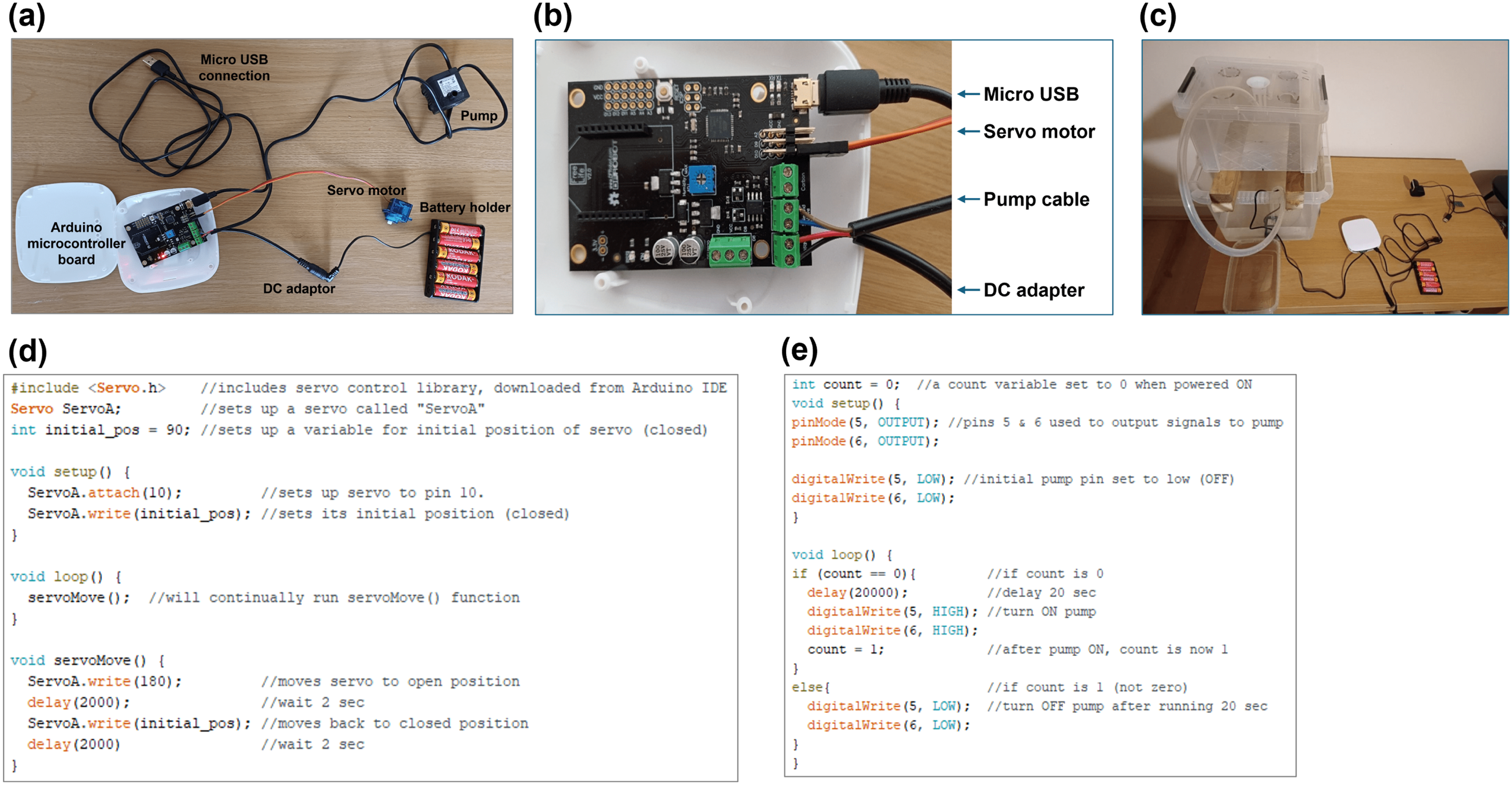
Electronics setup for the pump and dispenser. (a) Components connection for running the pump and the servo motor (b) Wiring connection to the microcontroller (c) Final setup of the electronics component to the aquaponic system (d) Sample code for running the servo motor adapted from Ref. Arduino 16 (e) Sample code for running the pump adapted from Ref. DFROBOT. 25
Figure 8(d) provides an example of the code used to control the servo motor for the nutrient dispenser. The servo motor operates by rotating a disc from its initial closed position to an open position before returning to its original closed position, effectively functioning as a gate to dispense nutrients. Figure 8(e) illustrates an example of the code used to control the pump, detailing the pin assignments for writing commands to activate and deactivate the pump over a duration of 20 seconds.
Electronics design for rack and pinion lifting mechanism
The electronic components utilised in this study include two servo motors (for the lifting and lowering mechanism), a voltage regulator, a power supply (9 V battery), a soil moisture sensor, and an Arduino microcontroller board. All components, except for the soil moisture sensor, are part of the Arduino Starter Kit. 16 The soil moisture sensor is sourced from the DFROBOT EcoDuino – An Auto Planting Kit. 25
The wiring configuration of the circuit is depicted in Figure 9(a). The linear voltage regulator receives the power supply input and steps down the voltage to 5 V, which is subsequently distributed to the Arduino board, the servo motors, and the soil moisture sensor. To ensure reliable communication among components, all elements share a common ground, establishing a consistent reference point for voltage levels. The corresponding pin connections for each component are detailed in the accompanying table in Figure 9(a).
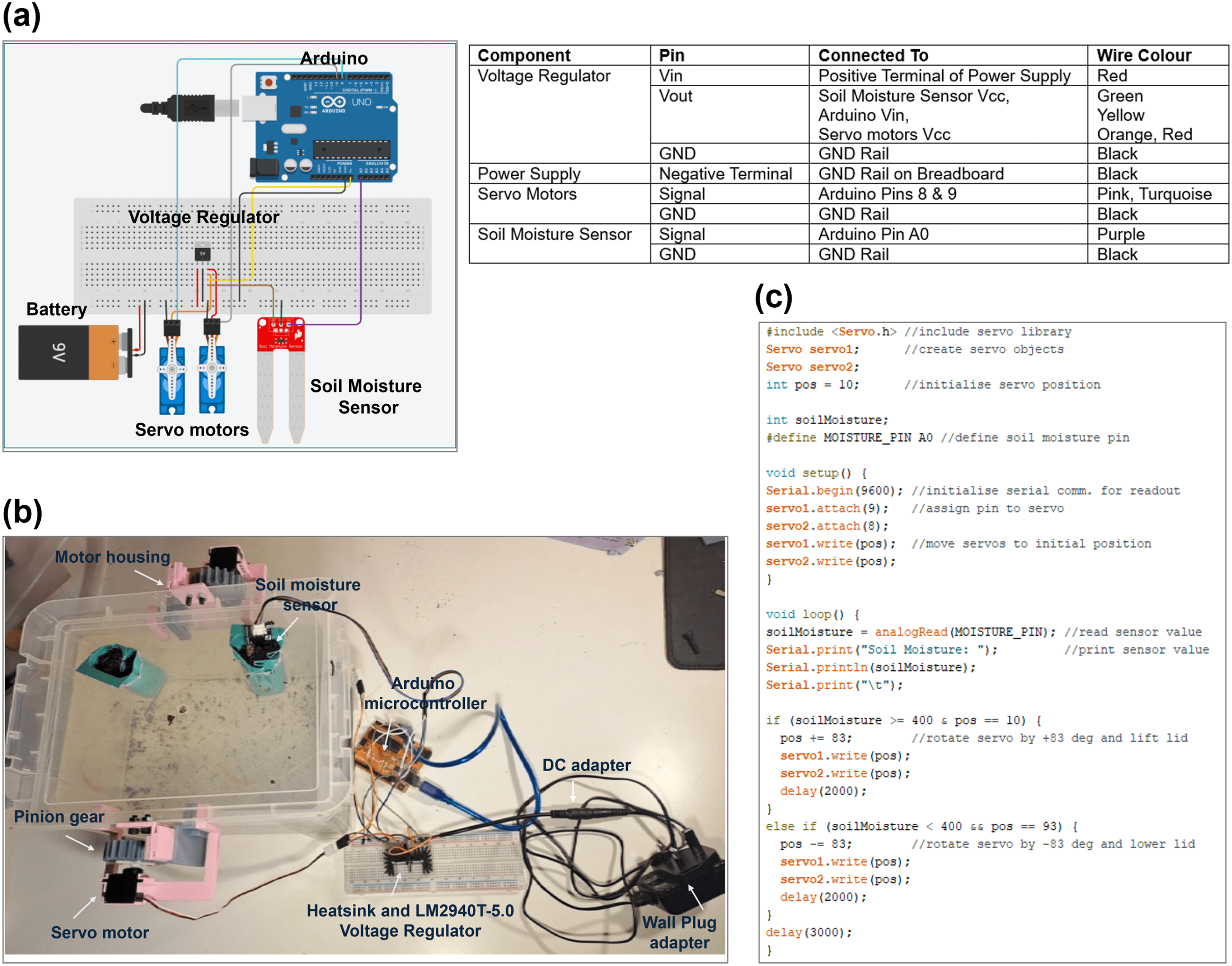
Electronics setup for the rack and pinion lifting mechanism. (a) Wiring configuration the servo motor with pin connections in the accompanying table (b) Final setup of the electronics components to the plant container part of the aquaponic system (c) Sample code for running the two servo motors based on the values of the soil moisture sensor.
The final setup, integrated into the plant container of the aquaponic system, is illustrated in Figure 9(b). Note that we included a heat sink in the final setup to allow better heat dissipation from the voltage regulator. Figure 9(c) presents an example of the code used to control the two servo motors, enabling the lifting and lowering of the plant container based on the readings from the soil moisture sensor (see also Supplementary Video 1 in Zenodo under the ‘Data availability’ section).
Various experimental setups for teaching
With the full aquaponic systems assembled, several dedicated experimental setups can be designed to teach specific mechanical engineering concepts. Here, three experimental setups are discussed for illustration.
Nutrient diffusion experimental setup
This experiment investigates the influence of dispensing distance from the pump on the concentration of fish nutrients transferred to the plant. The nutrient, represented by food colouring, will be dispensed at four distinct locations away from the pump as shown in Figure 10(a). Following the dispensation, the pump will be activated for a specified duration, and the nutrient concentration at the plant container–indicated by colour intensity–will be recorded. The resulting images from each dispensing location will be analysed to evaluate diffusion properties in relation to dispensing distance. Within the context of an aquaponics system, the movement of the food colouring simulates the transport of fish excretion from the fish container to the plant container.
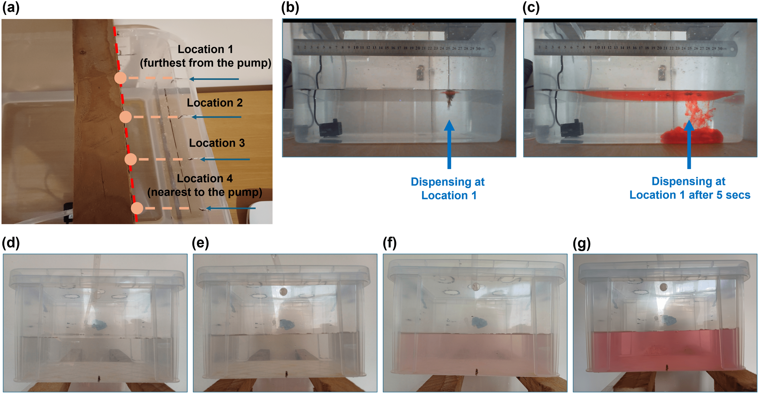
Diffusion experimental setup. (a) The four locations where the nutrient is dispense (b) Start of nutrient dispensation at Location 1 (c) Nutrient dispensation at Location 1 after 5 secs (d) Nutrient concentration at the plant container with nutrient dispensation at Location 1 (e) Location 2 (f) Location 3 (g) Location 4.
Figures 10(b) and (c) depict the diffusion of the nutrient when dispensed at Location 1 after 5 seconds (see also Supplementary Video 2 in Zenodo under ‘Data availability’ section). By analysing this diffusion, students can determine the properties related to the diffusion of the nutrient. Example of question that can be asked to the students while performing this experiment is as follow:
Example of diffusion related lab task question
Determine the diffusion coefficient,
Example of solution
The corresponding nutrient dispensed at Location 1 is 25 cm as indicated by the ruler attached to the fish container. After 5 seconds, the nearest detectable nutrient to the pump is 20 cm. Thus, using simplified Fick’s Law, where 
On the plant container side, Figures 10(d) to (g) illustrate variations in the intensity of the food colouring when the nutrient is dispensed at different locations. Students will observe that the most intense colour occurs when the nutrient is introduced closest to the pump. To support inquiry-based learning in engineering education–an approach aimed at enhancing students’ reasoning skills, 26 an example of lab task question is as follow:
Example of observation-based lab task question
Based on the observation shown Figures 10(d) to (g), suggest a practical configuration of the aquaponic system for optimising nutrient delivery from the fish container to the plant container.
Example of solution
The observation shown in Figures 10(d) to (g) suggests that, for optimal nutrient absorption by the plant, the nutrient should be dispensed as near to the pump as possible.
In practical applications, while it is not feasible to control where fish excretion waste, design modifications in aquaponic systems could encourage fish to congregate near the pump, thereby increasing the likelihood of waste being expelled in its vicinity.
Effect of nutrient on plant growth experimental setup
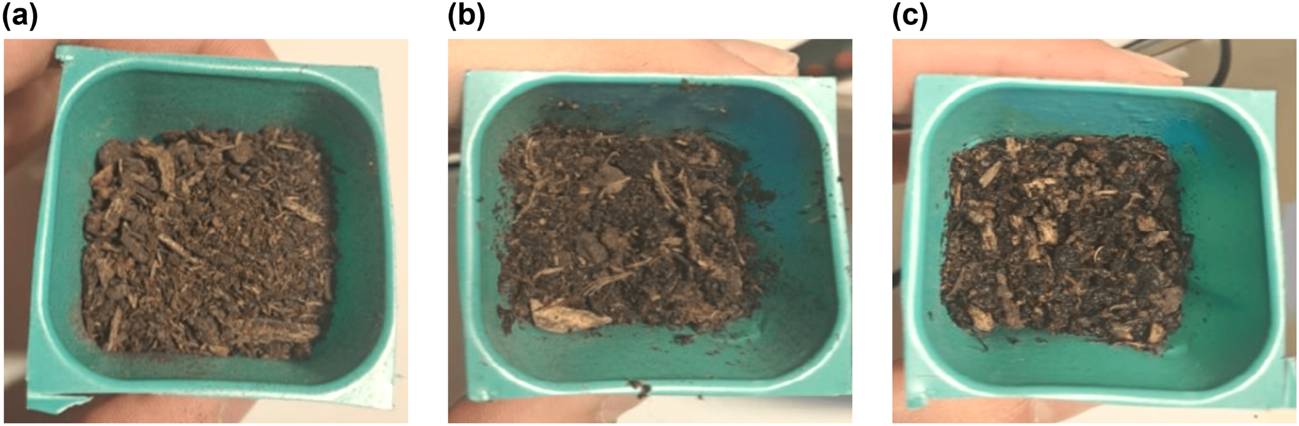
This experiment investigates plant growth in relation to the distance from which fish-derived nutrients are dispensed, using lettuce seeds (Lactuca sativa). 27 The experiment was conducted using two setups, each consisting of two nursery cups containing lettuce seeds. One setup served as a Control Experiment (hereinafter termed ‘Control’), which serves as baseline for comparison, where plants were grown solely in water without any nutrient supplementation (Figure 11(a)). The second setup consists of the nutrient-enriched water circulated to the plant containers via a pump (hereinafter termed ‘Pump’). Nutrients were dispensed at two distinct locations: the point furthest from the pump (Location 1) and the point nearest to it (Location 4). In this setup, Miracle-Gro plant nutrient 28 was used as a surrogate for the nutrients typically produced through fish waste.
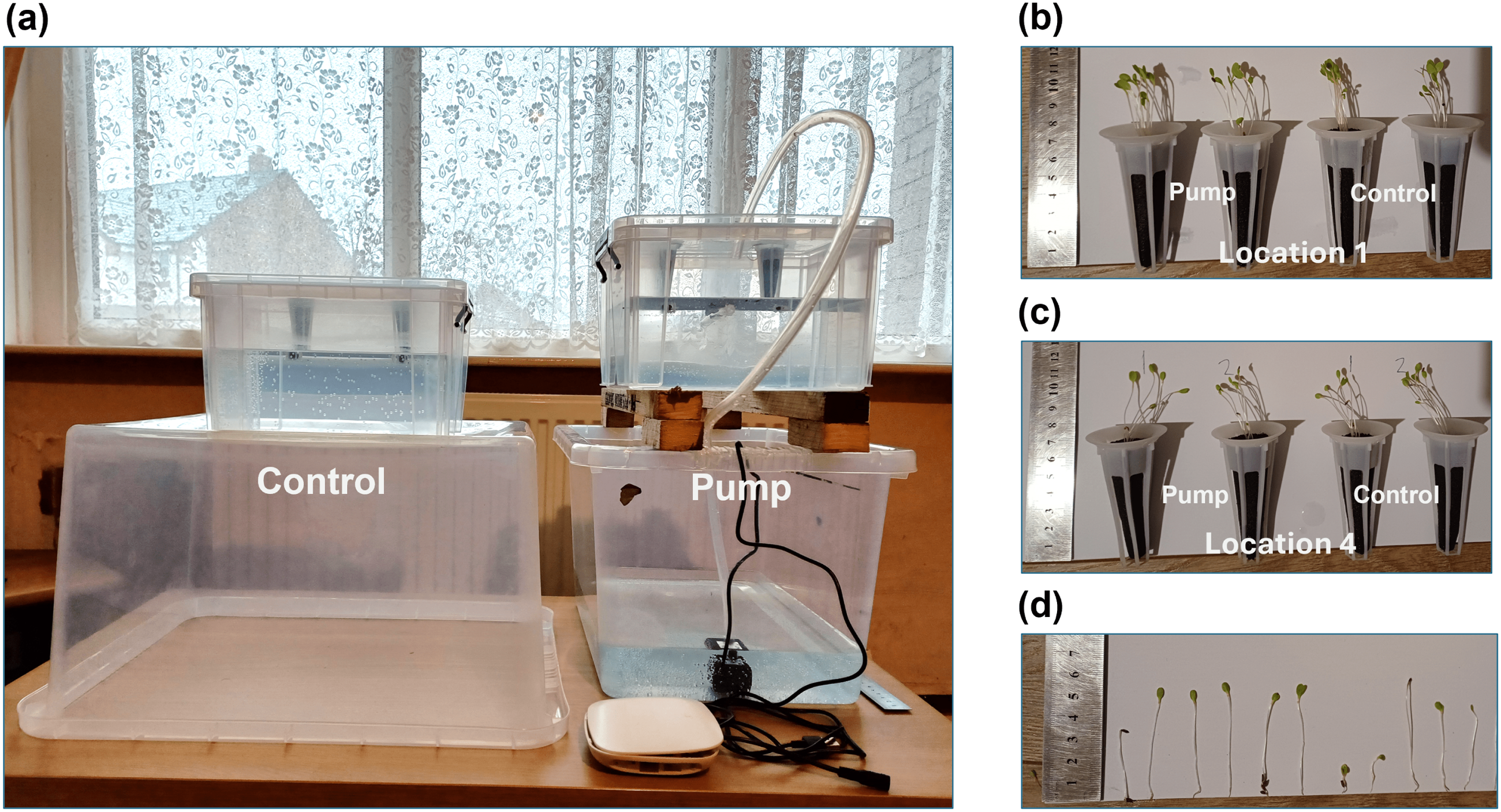
Plant growth experimental setup. (a) Two sets of setup with the one on the right is the aquaponic system and the one on the left is used a control experiment without any pump. (b) Plant growth after 10 days when nutrient is dispensed at Location 1 (farthest from the pump) (c) Plant growth after 10 days when nutrient is dispensed at Location 4 (nearest to the pump) (d) Illustration of the measurement of plant growth.
Both setups were placed side by side to ensure that environmental conditions, such as light and temperature, remained consistent throughout the experiment. Plant growth was monitored and recorded over a period of ten days. This duration was selected to strike a balance between the germination period for lettuce, as indicated on the seed packaging, 27 and the time constraints of the project.
The experimental results are presented in Figure 11(b) for nutrient delivery at Location 1, and in Figure 11(c) for delivery at Location 4. Stem length was used as a quantitative metric for plant growth, 29 as shown in Figure 11(d). It is worth noting that non-uniform growth is common, even among plants grown within the same nursery cup.
Based on the results of the previous experiment on nutrient diffusion, students can be expected to formulate and test the following hypotheses:
Hypothesis 1
“Plants grown with nutrient supplementation (via pump) will exhibit faster development over the same time period than plants grown without nutrients (control).”
Hypothesis 2
“Plants receiving nutrients dispensed nearest to the pump will develop faster over the same time period than those receiving nutrients dispensed furthest from the pump.”
Students are encouraged to evaluate these hypotheses from both qualitative and quantitative perspectives to provide a comprehensive justification and to enhance the reliability of their conclusions.
Example of qualitative observations
Plants grown under Pump and Control setups (Figures 11(b) and (c)) exhibited similar qualitative growth in terms of the number of germinated seedlings (i.e., successful sprouting of seeds 30 ) and observable stem length. These similarities suggest that qualitative observations alone may not be sufficient to conclusively test Hypothesis 1.
However, plants grown with nutrients dispensed at Location 4 appeared to have slightly longer stems than those at Location 1. This observation provides preliminary qualitative support for Hypothesis 2. To draw more robust conclusions, further quantitative analysis is recommended to substantiate both hypotheses.
Example of quantitative results
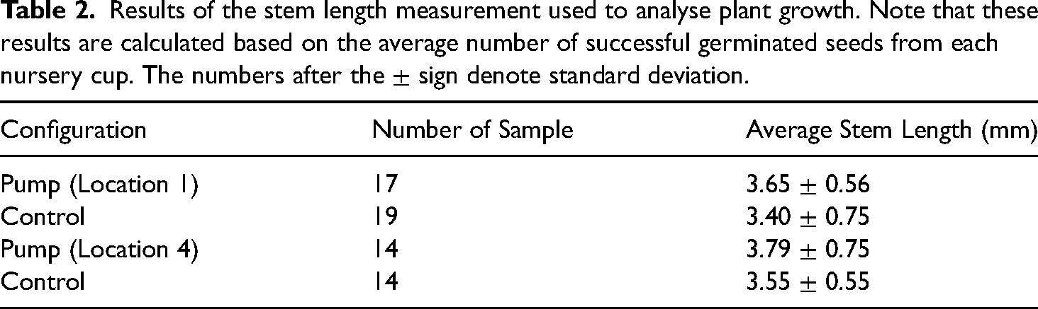
Table 2 shows the stem length measurement for experiments associated with the test of Hypotheses 1 and 2. For better visualisation, the results can be presented using bar graph with error bar as depicted in Figure 12.
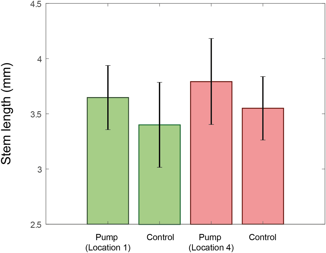
Bar graph depiction of Table 2.
Results of the stem length measurement used to analyse plant growth. Note that these results are calculated based on the average number of successful germinated seeds from each nursery cup. The numbers after the
The bar graphs indicate that plants exhibit improved growth when nutrients are provided, as evidenced by the shorter stem lengths in the Control compared to the Pump, thereby supporting Hypothesis 1. Specifically, when comparing the Pump (Location 1) to Control, plants showed a growth increase of
Furthermore, plants demonstrated greater growth when nutrients were dispensed nearer to the pump. The stem length in Pump (Location 4) was longer than Pump (Location 1), thereby supporting Hypothesis 2. The increase in growth was
An additional critical consideration in analysing these quantitative results is the role of measurement error. Students should be made aware of the importance of error analysis, particularly in the context of biological measurements, where variability and uncertainty can significantly influence results. 31
Soil moisture feedback control experimental setup
This experiment investigates optimal irrigation for plants based on soil moisture measurements. To design an effective feedback response mechanism, it is first necessary to determine an appropriate soil moisture threshold that triggers the control system.
Example of soil moisture calibration task
Using data from two prior studies,19,20 determine soil the moisture classifications for this aquaponic system.
Example of solution
It was observed that completely dry soil (Figure 13(a)) produced a reading of 0. When the nursery cup was partially submerged in water (Figure 13(b)), readings ranged between 350 and 420. When fully submerged (Figure 13(c)), values ranged from 680 to 700. Based on these observations, the following classifications were established: (i) readings between 0 and 400 were categorised as ‘dry’; (ii) readings of 400 or higher were considered ‘moist’, prompting activation of the lifting or lowering mechanism; (iii) readings above 680 were classified as ‘wet’.
Soil moisture classification. (a) Completely dry soil with value 0 (b) Moist soil with value between 350 to 420 (c) Completely wet soil with value between 680 to 700.
Example of soil moisture category transition task
Determine the time required for soil moisture levels in the plant to transition between the identified categories.
Example of solution
It was found that soil with an initial moisture reading above 600 required over three days to drop below 300, after which the reading stabilised. For moisture values between 500 and 600, it took approximately one day to fall below 300. In the range of 400 to 500, the drying process took approximately 4 to 5 hours to reach that same threshold. This data is essential for optimising the timing of the feedback control mechanism, particularly in determining appropriate intervals for lifting or lowering the plant container.
Example of feedback control implementation task
Design a feedback control mechanism that optimises irrigation in the aquaponic system, based on the findings from the previous tasks.
Example of solution
Based on earlier findings, a soil moisture value of 400 was selected as the threshold between ‘moist’ and ‘dry’ conditions, which triggers the feedback control mechanism. Figure 14 illustrates the implementation of this feedback system in the irrigation process.
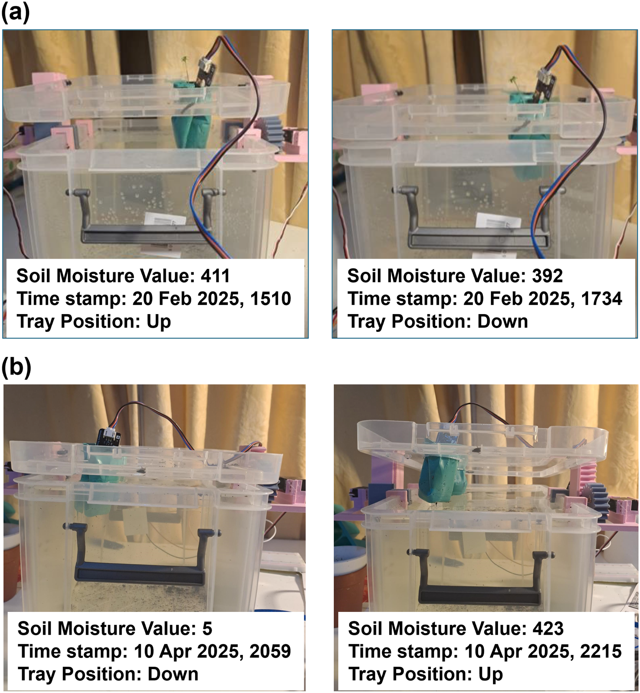
Feedback control system with soil moisture measurement. (a) The tray lid position changes from up to down when the soil moisture value drops below 400 (b) The tray lid position changes from down to up when the soil moisture value increase above 400.
In Figure 14(a), the soil moisture reading is 411, indicating a moist condition; consequently, the tray lid remains in the ‘Up’ position. Approximately two hours later, the moisture reading decreases to 392 (i.e. below the threshold of 400), prompting the control system to lower the tray lid, thereby submerging the nursery cup in water to initiate irrigation. In a separate experiment shown in Figure 14(b), the soil moisture reading is 5, indicating a dry condition; thus, the tray lid remains in the ‘Down’ position. After approximately one and a half hours, the moisture reading increases to 423 (i.e. above 400), triggering the control system to raise the tray lid, thereby terminating the irrigation process.
Mapping of learning concepts to modules
By applying concepts from multiple modules within the University of Warwick’s undergraduate Mechanical Engineering programme, this paper demonstrates a practical project that effectively bridges theoretical knowledge with real-world problem-solving. The interdisciplinary nature of the project makes it a highly versatile educational tool, capable of enhancing the technical competencies of students across a range of engineering disciplines. In this section, we map key learning outcomes to relevant modules from the Mechanical Engineering curriculum.
The module ES2D7: Systems and Software Engineering Principles emphasises the importance of understanding the broader context and implications of engineering projects, while also providing a holistic approach to the development and integration of various subsystems within a larger system.
Engineering design modules such as ES192: Engineering Design and ES2D2: Mechanical Engineering Design offered a structured methodology and design philosophy for this project. These modules also equipped students with essential skills including CAD, finite element analysis (FEA), and practical workshop experience.
The module ES191: Electrical and Electronic Circuits laid the theoretical foundation in circuitry, while ES2C6: Electromechanical Systems Design enabled the application of this knowledge in developing the rack and pinion mechanism triggered by soil moisture levels. Insights into gear characteristics from ES2D3: Motor Vehicle Technology informed the selection of an appropriate pinion gear, while understanding of power requirements from ES2C6, in combination with knowledge of thermal resistances from ES190: Dynamics and Thermodynamics, guided the selection of suitable components (e.g. appropriate heat sink for the voltage regulator) to ensure safe system operation.
Simulation and analysis capabilities were strengthened through ES192 and ES3E5: Finite Element Methods, which introduced techniques for evaluating design integrity and failure risks. In terms of programming and control systems, ES192 provided a foundation in Arduino IDE and electronic control, while ES197: Systems Modelling, Simulation and Computation fostered transferable skills in creative problem-solving, debugging, and critical thinking within a coding context.
The flexibility of this project allows students to explore various design pathways, constrained only by the context and requirements of their specific implementations. This creative freedom encourages deeper engagement with engineering principles and problem-solving strategies.
Furthermore, this project illustrates how the core skills and concepts taught throughout the undergraduate Mechanical Engineering curriculum serve as a solid foundation upon which students can build more advanced capabilities. Future developments of this project could include the integration of additional control parameters such as water temperature, turbidity, humidity, and nutrient concentration. At present, no real fish have been used in the system. A potential future development of this project involves incorporating virtual reality 32 to enhance learning and understanding of the role, welfare, and behavior of fish within the aquaponic system, as suggested in Ref. Baugerud. 33 These enhancements would enable students to broaden their technical expertise while designing and conducting more complex experiments. For instance, students could investigate the influence of the rack and pinion system on lettuce plant growth over the course of a month, thereby improving their experimental design and data analysis skills.
Evaluating student learning experience
This section presents two qualitative insights into the student learning experience throughout the project, as reported by the first and second authors. The first insight is drawn from observations of student engagement with the design cycle, while the second is based on students’ self-reflection reports, submitted as part of the final-year individual project assessment.
Student learning experience with the design cycle
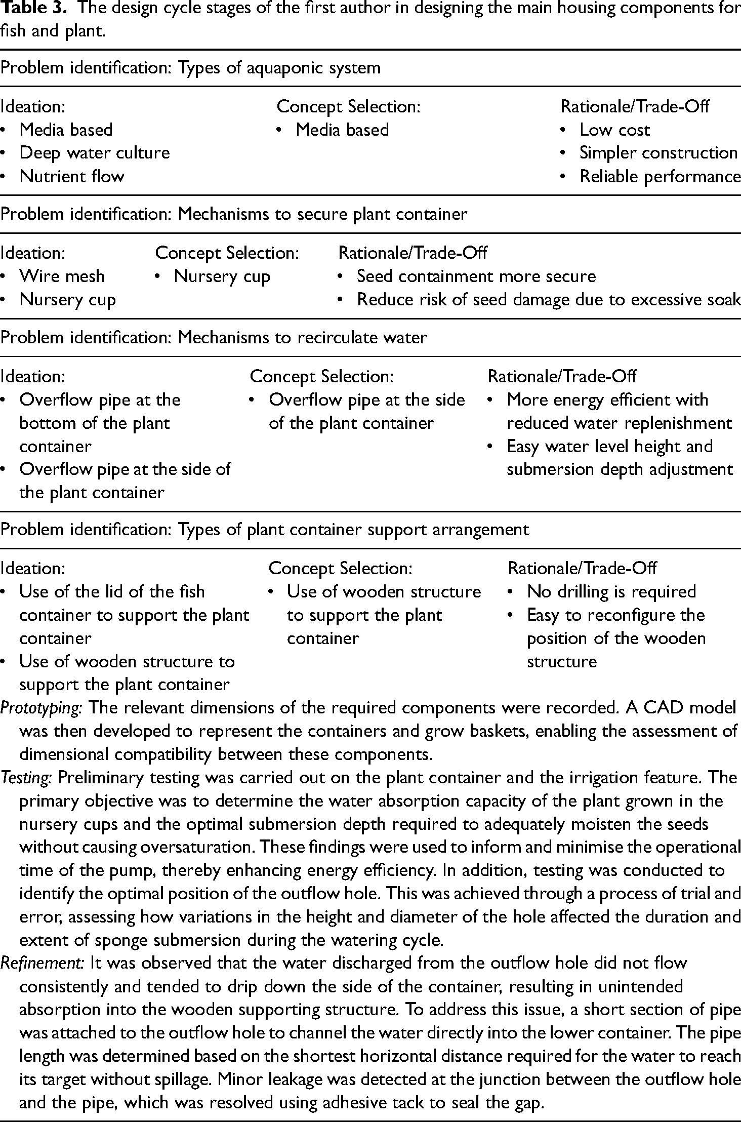
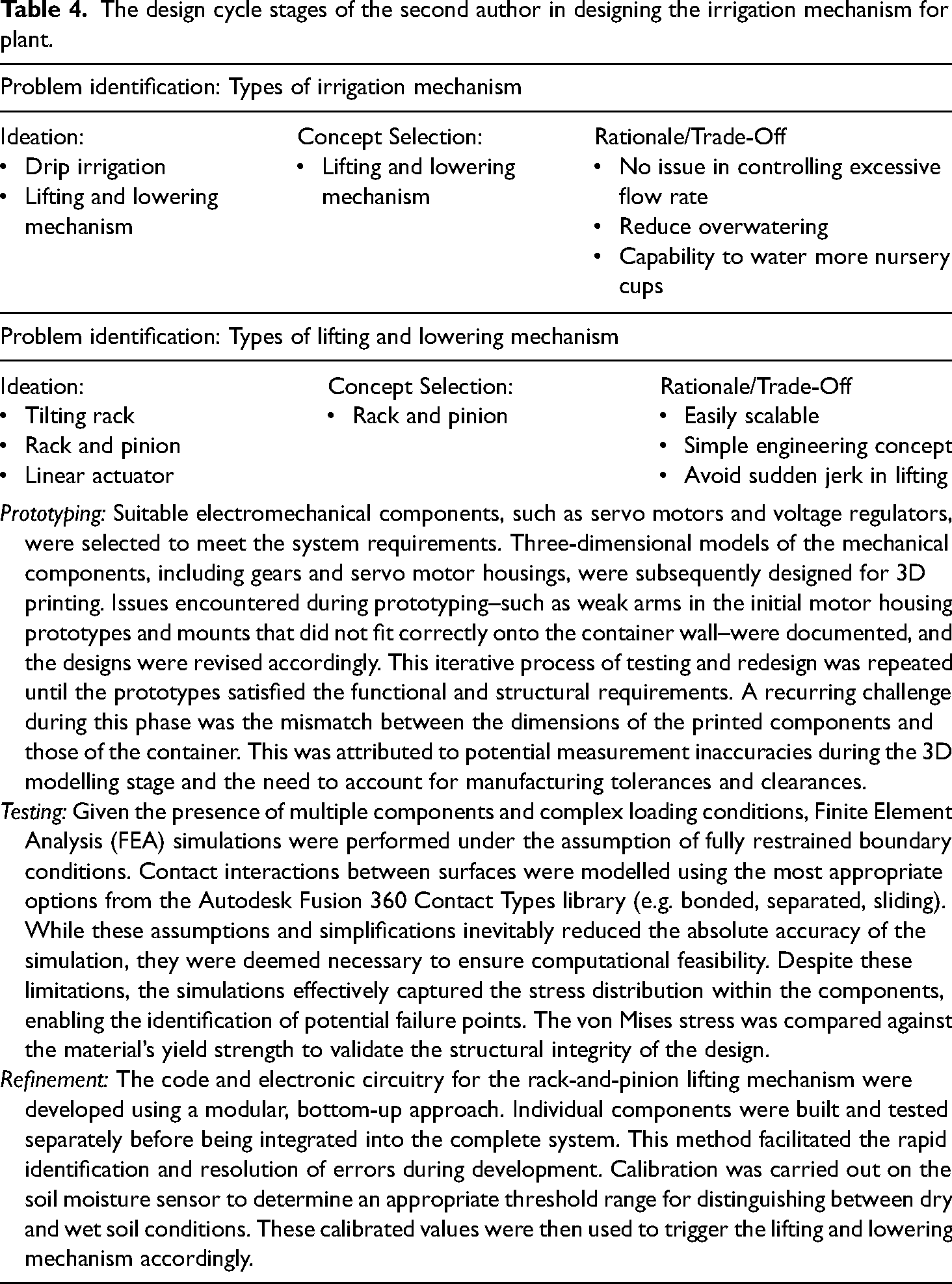
A typical design cycle comprises the stages of problem identification, ideation, concept selection, prototyping, testing, and refinement. This section presents the thought processes of the first and second authors at each stage of the cycle, highlighting the challenges encountered, the solutions proposed, and the rationale and trade-offs considered.
Problem Identification: At the initial stage of the design process, students define and characterise the problem their design seeks to address. This involves determining the scope of the project and may include the application of various project management tools and frameworks to support effective planning.
Ideation and Concept Selection: Following a clear articulation of the problem, students generate a range of potential solutions. Established brainstorming techniques are commonly employed to facilitate ideation, categorisation, and concept development. It is crucial that students approach the problem creatively and from multiple perspectives. Once initial concepts are developed, each is critically analysed and evaluated against predefined criteria and the overarching project objectives. Students assess the strengths, limitations, and requirements of each concept, while also identifying opportunities for refinement, before selecting one concept for further development.
Prototyping, Testing and Refinement: Upon finalising a concept, students proceed to prototype, test, and refine the relevant components. This iterative process is designed to systematically identify and resolve failures, thereby enabling progressive improvement of the design.
Tables 3 and 4, respectively, summarise the design cycle stages experienced by the students specifically in relation to the design of the main housing components for fish and plant and the irrigation mechanism for plant.
The design cycle stages of the first author in designing the main housing components for fish and plant.
The design cycle stages of the second author in designing the irrigation mechanism for plant.
Student learning experience through self-reflection report
Student self-reflection reports are often employed as qualitative tools to enhance students’ awareness of their learning experiences. These reports foster metacognitive skills by encouraging students to think critically about their learning journey–what they have learned, how they learned it, and what they still need to learn. 34 Here, the self-reflections are thematically categorised into four key skills — experimental design skills, subject-specific technical skills, time management skills and independent working skills.
Reflection against experimental design skills
Designing a suitable and informative experiment to test a hypothesis is a vital skill. A poorly designed experiment not only leads to a loss of time but also wastes valuable resources. Over the course of the project, the students recognised that they had developed the ability to meticulously plan experiments aimed at collecting relevant data, as well as to implement appropriate troubleshooting processes. This process was instrumental in deepening their understanding of experimental methodology and enhancing their confidence in applying these skills in future engineering contexts.
“Planning and doing the experiments has given me experience in setting up an experimental test. It is an important skill
“I also learned that technical troubleshooting (in experiment) can always take longer than expected, so future projects should incorporate sufficient buffer time for debugging.” — Ee Yeong (Second author).
Reflection against subject-specific technical skills
Students reported that the engineering design and electronics modules were particularly valuable in building their confidence. These modules enabled them to undertake more advanced design tasks, become proficient in technical terminology, and interpret datasheets with greater ease. This process not only reinforced their theoretical understanding but also highlighted the practical relevance of these skills in real-world engineering contexts.
“I have done 3D printing to produce the nutrient dispenser. This was a helpful CAD project (acquired from ES192: Engineering Design and ES2D2: Mechanical Engineering Design) as it gave me a design problem to solve. It involved including the servo motor, which had a disc to be 3D printed, as well as producing the dispenser in two pieces due to size constraints in the printer.” — Atif Hussain (First author)
“I found that drawing knowledge from the module ES2C6: Electromechanical Systems Design has been very helpful in understanding the jargon and concepts like duty cycle associated with linear push-pull solenoids. Reading various resources related to my academic modules has been incredibly helpful in familiarising myself with the technical terminology. It also helps that the datasheets often have relevant equations and notes. This is the same when I was doing research on servo motors as well.” — Ee Yeong (Second author)
Reflection against time management skills
Managing multiple tasks within a prescribed timeline is inherently challenging. The students unanimously agreed that while initial planning is essential, the ability to adapt to changes during task execution is equally important. They also recognised the value of incorporating buffer time to accommodate unforeseen issues. Additionally, students found that maintaining a logbook to document tasks was a useful practice for tracking progress and ensuring accountability. This project enabled students to better understand their working habits, improve time management, and develop a more structured approach to problem-solving–skills that are crucial for professional engineering practice.
“I think the initial scope and aim of the project was feasible and appropriate to time constraints. Therefore, there was not large changes required in the project. As I was working on the experiments, I think better planning was required for the experiments and I should have made a more informed Gantt chart of the updated work schedule when the experiments were being done. I could have considered doing things more simultaneously as some time may have been spent waiting for components and trying to solve certain issues when there were still necessary components to do one of the experiments. Project management was also done using a logbook which initially I thought would take up time and not provide value however it proved useful for me to store important information and reflections. It allowed me to have notes of all the issues and ideas with the project in one place which I can easily look back on to help me progress.” — Atif Hussain (First author)
“Because of the open-ended nature of the project’s scope, a specific and detailed plan could not be defined. A general timeline was still created to plan key milestones based on the initial guiding objectives, recognising that this will be subject to change. I also recognise that my time management skills were not the best then, and I was also prioritising other commitments. For future improvements, I believe it would be beneficial to allocate a sufficient but fixed portion of time to understanding a project, selecting an appropriate project management strategy, and include buffer periods to account for unforeseen issues. Breaking down tasks as much as possible and adjusting to changing priorities will be helpful in time management as well.” — Ee Yeong (Second author)
Reflection against independent working skills
Throughout the project, the first author demonstrated the ability to work independently with minimal supervision, with the exception of experiment design, where additional guidance was required. In contrast, the second author initially experienced uncertainty and a lack of confidence at the outset of the project. However, through appropriate supervisory support and reflective engagement, the second author gradually regained confidence in working independently. More importantly, the second author came to recognise the value of being proactive in seeking assistance from relevant sources is a skill identified as essential for effective problem-solving and professional growth in engineering practice.
“I think I worked well without much supervision when designing and assembling the system. I believe I was able to deal with these issues with the assembly and initial development of the system without close supervision. I think I took more guidance when deciding what types of experiments to do and how to further develop the first experiment into the second one. I think I worked well with managing time and making steady progress such that I didn’t need supervision to get me to increase my work progress.” — Atif Hussain (First author)
“During the initial stages of the project, because I was quite unsure about the direction of the project, and did not quite understand how to solve the problems associated with the soil, I believe I did not work reliably independently. I was quite inefficient with the tasks I was doing with the soil because there was a lot of waiting involved, and I didn’t quite know what to do. However, with the help and input of my supervisor, I was able to eventually generate my own ideas and conduct my own tests. Going forward, it would be beneficial to remain proactive in all projects that I do and to reach out to the relevant people when I need help.” — Ee Yeong (Second author)
Conclusion
The aquaponic system represents a highly versatile platform for teaching and learning within mechanical engineering education. In this paper, we have demonstrated how a range of learning concepts have been integrated and applied to develop a lab-scale aquaponic system within the GBP 200 budget (overall cost GBP 143.19) and time constraints of 24 weeks.
Using CAD, key components of the media-based aquaponic system, nutrient dispenser, and rack-and-pinion lifting mechanism were designed. Finite element analysis (FEA) was employed to investigate the stress distribution within the rack-and-pinion mechanism. Embedded control design facilitated the implementation of the irrigation pump, nutrient dispensing unit, and soil moisture feedback control system. Finally, through electronic circuit design, an Arduino microcontroller was programmed to interface with the relevant electronic components. In terms of the students’ learning experience, they were able to engage with each stage of the design cycle in detail, enabling them to develop effective engineering solutions to the problems they encountered. Moreover, the project significantly contributed to the development of relevant skills, better equipping them for professional practice as engineers upon graduation.
The system is inherently modular and highly adaptable, making it suitable for a wide range of learning objectives. For example, if the impact of water temperature and pH on plant and fish growth is to be explored, corresponding temperature and pH sensors can be easily integrated. This flexibility and expandability make the aquaponic system an invaluable educational tool, enabling students to tailor the system according to specific objectives while developing a broad range of technical and interdisciplinary skills.
Footnotes
Acknowledgements
The authors would like to acknowledge the financial support from the School of Engineering, University of Warwick for all the equipment purchase.
Declaration of conflicting interests
The authors declared no potential conflicts of interest with respect to the research, authorship, and/or publication of this article.
Funding
The authors received no financial support for the research, authorship, and/or publication of this article.
Data availability statement
All the IDE codes and CAD designs are available in Zenodo and can be downloaded from Ref.
35
(![]() ).
).
Supplemental material
Supplemental material for this article can be found from Ref.
35
(![]() )
.
)
.