
Abstract
As an effective method to strengthen blast furnace (BF) smelting and to realize reduced fuel operation, high-proportion pellet charging has become an inevitable trend in the BF ironmaking. However, due to the high rolling characteristics of pellets and the low repose angle of stockline, the high-proportion pellet charge structure also brings some difficulties to the control of gas distribution and the BF operation. In order to find out the burden distribution characteristics in the BF under high pellet ratio and provide theoretical guidance for improving the operation of high pellet ratio of the BF, a mathematical model of the upper part of the bell less BF is established, and the influence of pellet ratios on the burden distribution is analyzed by a discrete element method (DEM). The results show that as the proportion of pellet increases from 10% to 50%, the width of the stockline platform decreases from 1.081 m to 0.895 m, and the stockline angle decreases from 34.00° to 31.63°. With the increase in the proportion of pellets, the porosity of the stockline decreases, and the porosity along the radial direction from the furnace wall to the center also decreases gradually.
Introduction
The BF is a huge counter-current, moving bed reactor in which iron-bearing materials are charged in layers from the top, while hot blast blown from the bottom through tuyeres.1–5 The ironmaking of BF is still one of the best ways to extract pig iron due to its large capability and adaptability to different grades of iron ore. However, with the deterioration of the ecological environment and the intensification of global warming, the iron and steel industry faces great structural changes. 6 As the sintering process can cause serious environmental pollution, restrictions have now been placed on the sintering process. Therefore, increasing the proportion of pellets in the BF has become an inevitable trend.
Compared with sinter, the pellet has the characteristics of a small and round shape making this raw material more prone to roll on the burden surface and percolate into the void between larger (coke) particles. 7 Based on the above analysis, it is necessary to study the burden distribution in the BF after increasing the pellet ratio. The burden distribution in the throat of the BF is of importance for maintaining smooth burden descent and efficient gas utilization. 2 Many investigations have considered the burden distribution in BFs using both experimental and numerical techniques based on the discrete element method.8–17 Narita et al. 9 analyzed the influence of uneven charging along the circumferential direction of the furnace burden and the trajectory of the furnace burden from the rotary chute, and concluded that reducing the chute angle can effectively improve this phenomenon. Yu et al. 11 studied the behavior of intergranular infiltration from small particles (pellets) to large particle (coke) layers during the decline of the BF burden by DEM simulation. Holzinger and Schatzl 14 simulated the influence of different chute starting angle and rotation direction on the mass distribution of the layer of charged burden through DEM, and verified this conclusion through industry. Hiroshi et al. 15 simulated the behavior of particles in the charging process of the BF by DEM, predicted the particle trajectory in the BF, and verified the simulation results in a 1/3 scale experimental BF, but did not describe the burden distribution after the particles were fed into the furnace. Based on the DEM, the above studies confirm that DEM is a feasible and reasonable way to investigate the state of burden distribution in the BF.
High pellet ratio smelting is an important future development direction for the BF ironmaking, and a lot of work has been done on research related to high pellet ratio ironmaking in the BF.18–22 Wang 18 measured the relevant parameters of high pellet ratio pile, and calculated the stock surface shape and charge layer structure by using Visual Basic language. Gupta et al. 19 theoretically analyzed the impact of high pellets on the BF operation, put forward measures to optimize the BF operation, and verified them industrially, but did not analyze the specific impact of high pellet ratio on the burden distribution. Gupta et al. 19 based on the results observed in the operation of the BFs, discussed the influence of the addition proportion of pellet on the working index, gas utilization, permeability, fuel ratio and productivity of the BF. All the above studies describe the burden distribution under the condition of high pellet ratio, but they mainly use the particle model or field data analysis, and cannot analyze the influence of high pellet ratio on the charging process from a micro perspective. At present, the proportion of pellets in the burden structure of China is mostly 10%−30%. In this paper, taking a bell-less top charging system BF as an example, the distribution process under different pellet ratio is simulated, and the movement and distribution of particles are analyzed from a microscopic perspective, which provides theoretical support for the operation of high pellet ratio in the BF.
Model description
DEM model
DEM is a numerical calculation method for solving and analyzing the motion laws and mechanical characteristics of complex discrete systems. By tracking and calculating the microscopic motion of each unit, the macroscopic motion law of the entire research object can be obtained.
23
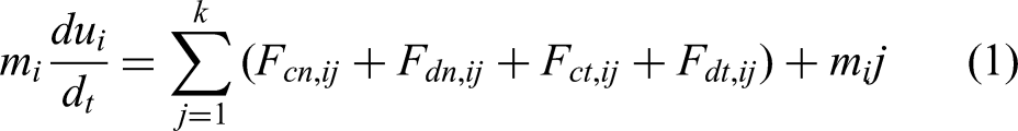
It is one of the most feasible numerical approaches for the analysis of particle behavior, by tracking the translational and rotational motion of each element in agranular system using Newton's second law of motion. The contact between two particles is given by a Voigt model, which consists of a spring-dashpot and a slider for friction in the tangential component, as illustrated in Figure 1. The governing equations for particle i contacting with another particle j are as follows24,25:
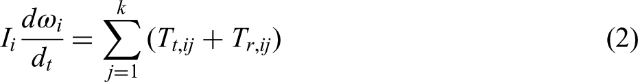
Schematic illustration of contact model between particle i and j in DEM.
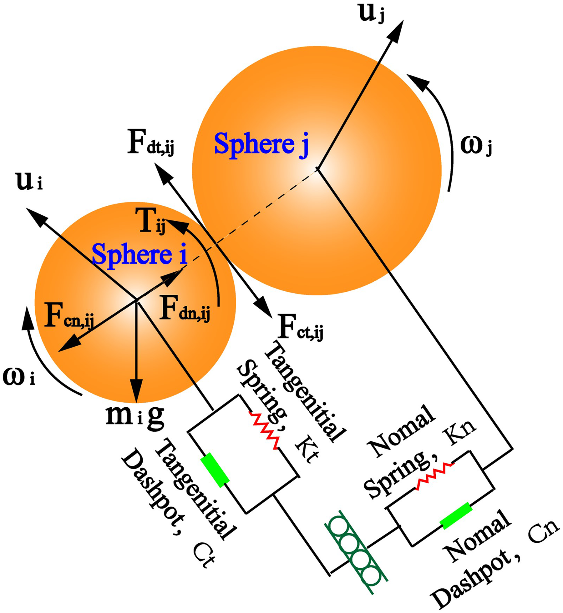
Forces and torques acting on particle i.
Simulation conditions
Based on an industrial BF in China, the geometric model of a bell-less top BF was established, as shown in Figure 2. In practice, ores charged into the BF of the ironmaking plant consist of sinter, pellet and lump ore, whose ratios are 70%, 17%, and 13%, respectively. The present work concentrates more on the effects of sinter and pellet on the burden distribution since lump ore has a small impact.
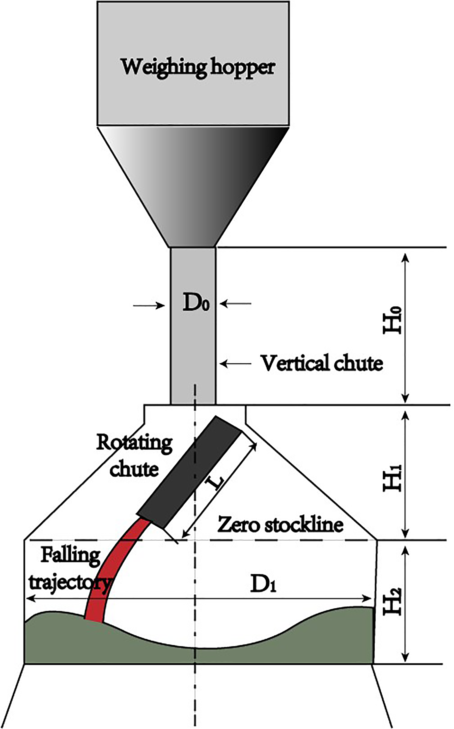
Model of the bell-less top BF with dimensions and notation.
The charging process of the BF is simulated by DEM. During charging, sinter and pellets are generated above the weighing hopper initially, and are then released to fall through the central throat tube to the surface of the rotating chute, where the materials slide down. Finally, the materials are charged into the stock surface by the rotating chute. The sizes of pellet and sinter are three times enlarged in the simulation to reduce the number of particles in the system and the calculation time used in the calculation. This method is frequently used in DEM simulations, especially when the model under consideration is quite large.26,27 Furthermore, after enlargement, the largest particle size is 135 mm, while the throat diameter is 5.5 m, which is 40.7 times larger than particle size. The throat diameter to particle diameter ratio is too large to have an impact on the mixing/segregation pattern. As a result, increasing particle size is reasonable and reliable without compromising simulation accuracy.
One of the major flaws of traditional DEM is that the particles are assumed to be spherical, which has a significant impact on the results. The irregular and different shapes of sinter were considered in this study's modeling. The irregular particles were handled using the clumped sphere model, which approximates different shapes by multiple spheres that are rigidly connected to each other (Figure 3). The shapes were chosen to resemble the most common sinter particle shapes. All of the particle shapes were generated with the same probability and had the same physical properties.
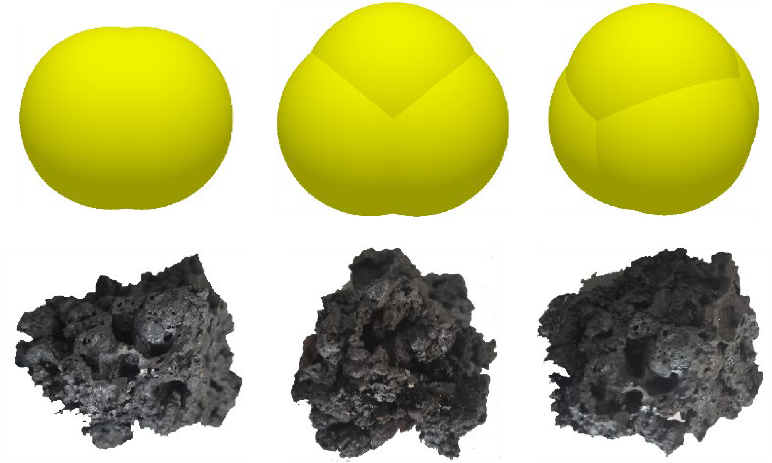
Sinter particles of different shape and their representation using the clumped sphere model.
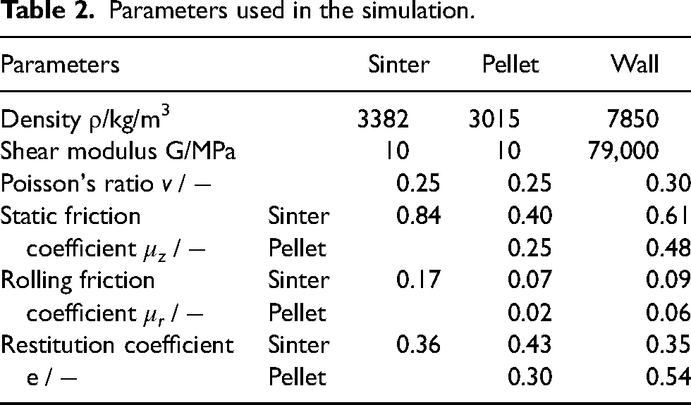
The geometries in the simulated model, including hopper, rotating chute, the BF top, and so on, are made of steel, and they are defined as wall generally. The parameters like shear modulus, poisson's ratio, friction coefficient, and so on, are taken from literatures and the material databases, illustrated in Table 2.28–30
Parameters used in the simulation.
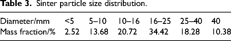
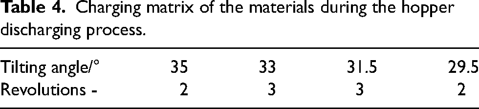
In this paper, the influence of the proportion of pellets on the burden distribution is studied when the proportion of pellets is 10%, 20%, 30%, 40% and 50%, respectively. The particle size distribution of the sinter is given in Table 3. The particle size of pellets is constant, 12 mm. To mitigate the calculation load, the sinter, pellet and lump ore diameters have been magnified three times to reduce the total number of particles, and the distribution matrix is shown in Table 4.
Sinter particle size distribution.
Charging matrix of the materials during the hopper discharging process.
Results and discussion
Model validation
Based on the large space occupied by the BF charging equipment, it is unrealistic to establish the same experimental model as the actual one. In order to verify the accuracy of the model, this paper verifies the model from two perspectives. On the one hand, according to the results of the distribution model experiment conducted, 28 the same distribution matrix was established, and the model was verified by comparing the distribution of furnace charge drop radius when the chute inclination was 35°. As shown in Figure 4, it can be seen that the calculated results of the burden falling point radius based on this model are in good agreement with the experimental results.
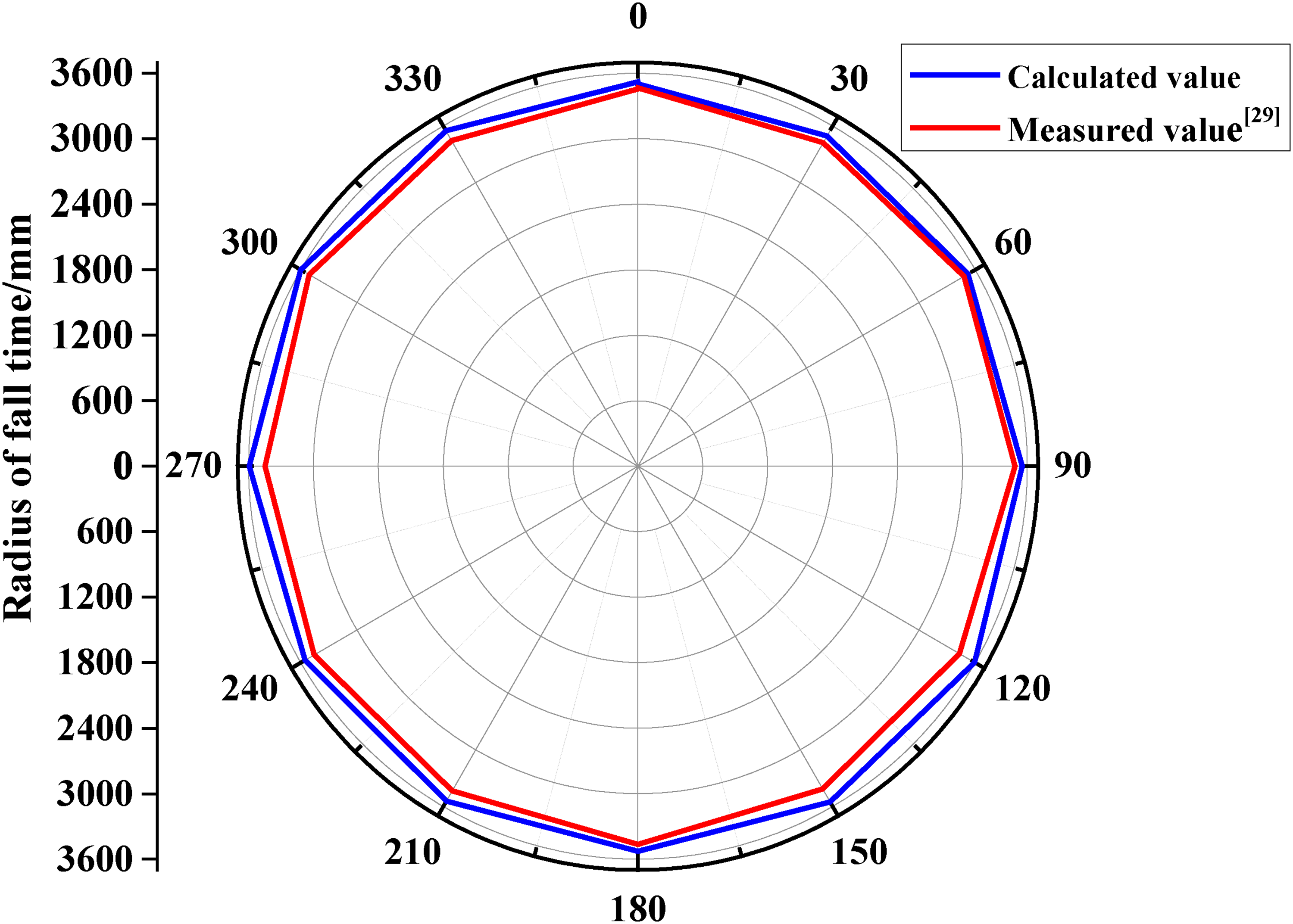
Comparison of distribution of burden falling point radius.
On the other hand, by comparing the width of the material pile platform obtained from the distribution model in this paper with the actual situation of the BF, the field verification shows that the coincidence degree is also relatively high. This is shown in Figure 5. Therefore, it can be concluded that this method of particle simulation of the bell-less charging process can predict the burden distribution in the BF.
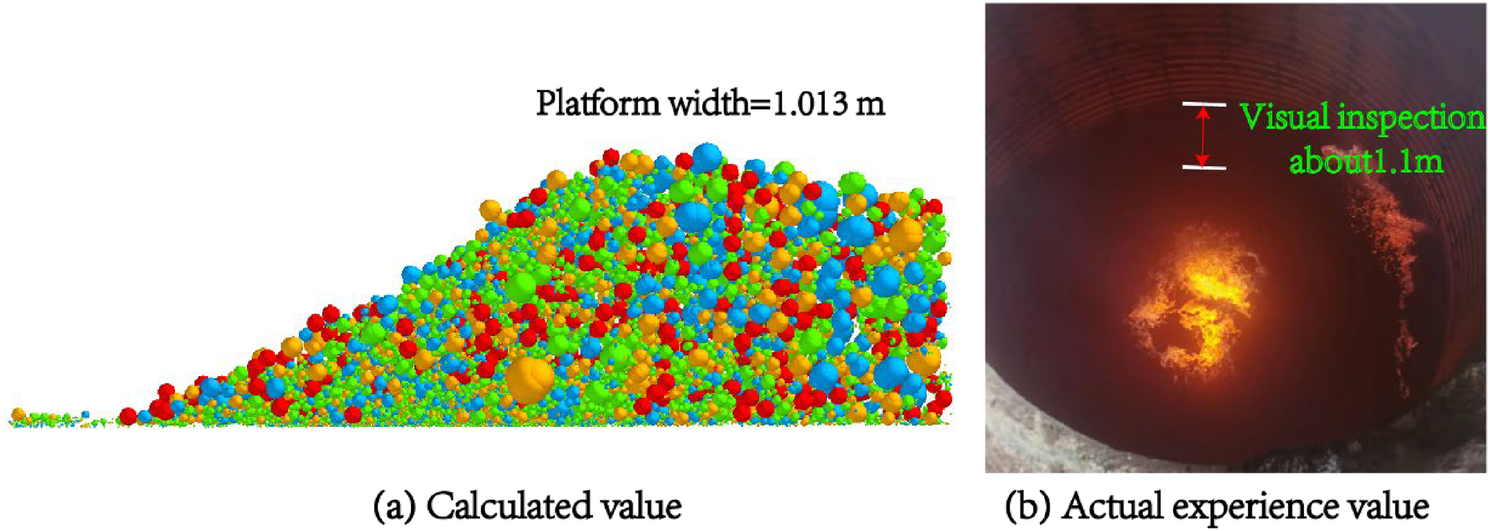
Comparison between calculated and actual platform width. Notes: red particles are pellets; the particles of other colors (green blue and orange) are sinter with different shapes, as shown in Figure 3.
Influence of different pellet proportion on burden distribution
Burden distribution at the end of chute
In order to understand the influence of different pellet proportion on burden distribution, the burden distribution at the end of rotary chute is analyzed first. Several virtual volume areas are set at the end of the chute, as shown in Figure 6, which are top, middle, bottom and left, middle and right respectively, and the burden distribution at the same time under different conditions is compared. To evaluate the burden segregation at the chute outlet, a segregation index (SI) was introduced to analyze the burden distribution in the vertical and horizontal directions at the chute outlet. It can be expressed as follows: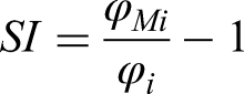
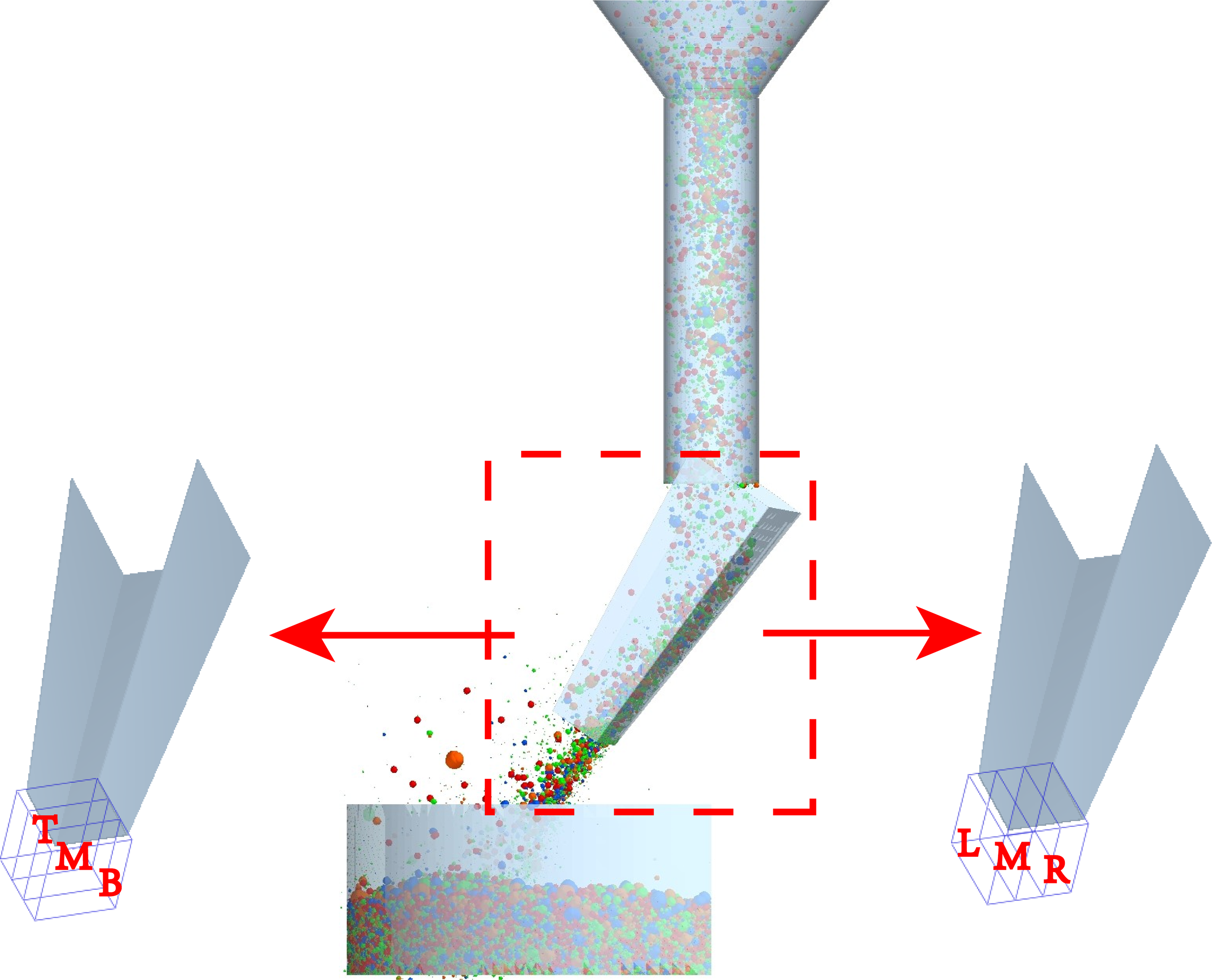
Schematic diagram of chute outlet position monitoring.
SI > 0 indicates that the proportion of pellets at this position is higher than the average level; SI < 0 indicates that the proportion of pellets at this position is lower than the average level.
Figure 7 shows the segregation distribution of pellets monitored in the upper, middle and lower three virtual volumes. The purpose of monitoring the top, middle and bottom areas is to analyze the distribution of furnace charge at this position and then connect it with the law of the falling point of furnace charge on the stock surface. However, due to the bouncing of the burden after falling on the rotary chute and the strong randomness of the generation and falling of the burden, it is found that when the proportion of pellets is 20% and 30%, the segregation index of pellets first increases and then decreases from top to bottom, and the segregation index in the upper region is the smallest and less than 0. When the proportion of pellets is 10%, 40% and 50%, the segregation index decreases from top to bottom. To sum up, the analysis of this area provides guidance for the burden distribution of the final charge level.
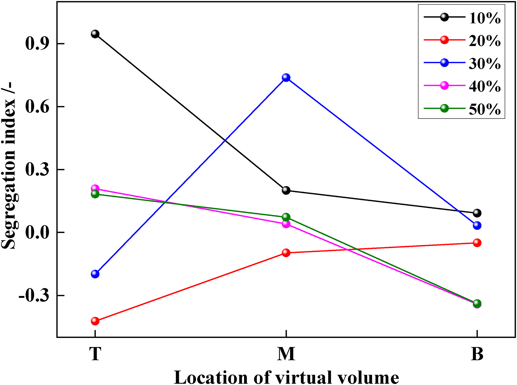
Variation of pellet segregation index in the top, middle, and bottom three virtual volumes.
Figure 8(a) shows the changes in the mass of pellet ore monitored in the three virtual volumes on the left, middle, and right. It can be seen that the mass of pellet ore on the right is basically the largest, which is due to the clockwise rotation of the rotating chute, and the furnace charge will be stored at the right end of the chute due to inertia, so the mass of furnace charge on the right is the largest. Figure 8(b) shows the segregation distribution of pellet ore monitored in the three virtual volumes on the left, middle, and right. It can be seen that under different pellet ore ratios, the segregation index in the middle of the chute is the smallest, indicating that the number of pellet ore in the middle of the chute is less than that at both ends of the chute. Therefore, it is inferred that the pellet ore is discharged from the middle of the chute first because of its good rolling performance. Combined with (a) and (b), it is found that although the charge on the right side of the chute is of high quality, it will not aggravate the segregation of the pellet.
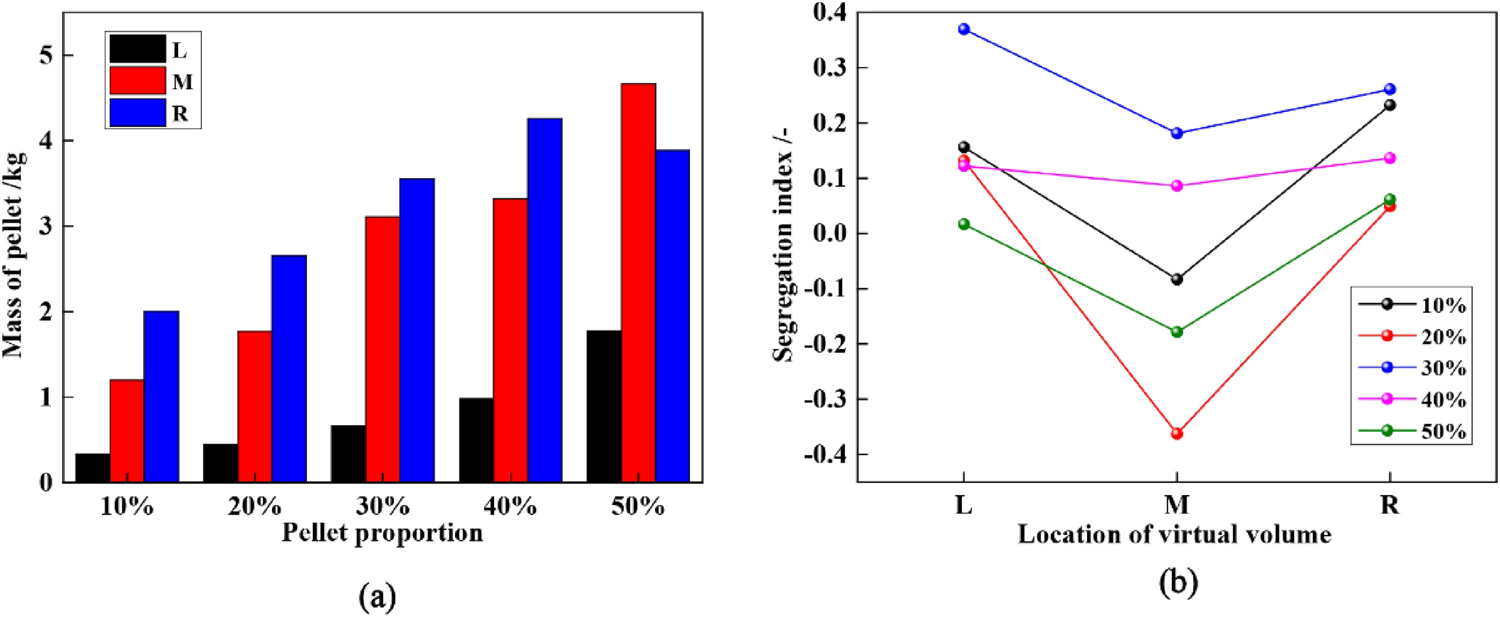
Variation of three virtual volume segregation indexes on the left, middle, and right.
By comparing the different segregation conditions at the end of the chute, combined with the conclusions in Figures 7 and 8, although it can be concluded that the pellet is discharged preferentially from the middle of the chute, the burden distribution at the end of the chute and the burden distribution at the charge level cannot establish an effective relationship.
Burden distribution at the stock surface of furnace throat
After the charge leaves the rotary chute, it is distributed in the throat along the circumferential direction. Due to the difference in charge shape and size, the charge distributed to the throat surface will also be different, which will have a certain impact on the smooth running of the BF. In previous studies, it has been found that the proportion of modified pellets has little effect on the circumferential burden distribution without changing the distribution parameters, so only the burden distribution in the radial direction of the stock surface is analyzed here. Figure 9 shows the burden distribution at the throat material surface under different pellet proportions. It can be seen that with the increase of pellet proportion, the proportion of red pellet in the stockline increases significantly, and the proportion of pellet near the corner of the stockline near the center of the throat increases relatively more. Therefore, it can be inferred that due to the larger rolling type of pellets, after the proportion of pellets increases, more pellets will fall at the stacking angle, and the overall pile will move to the center of furnace throat to a certain extent.
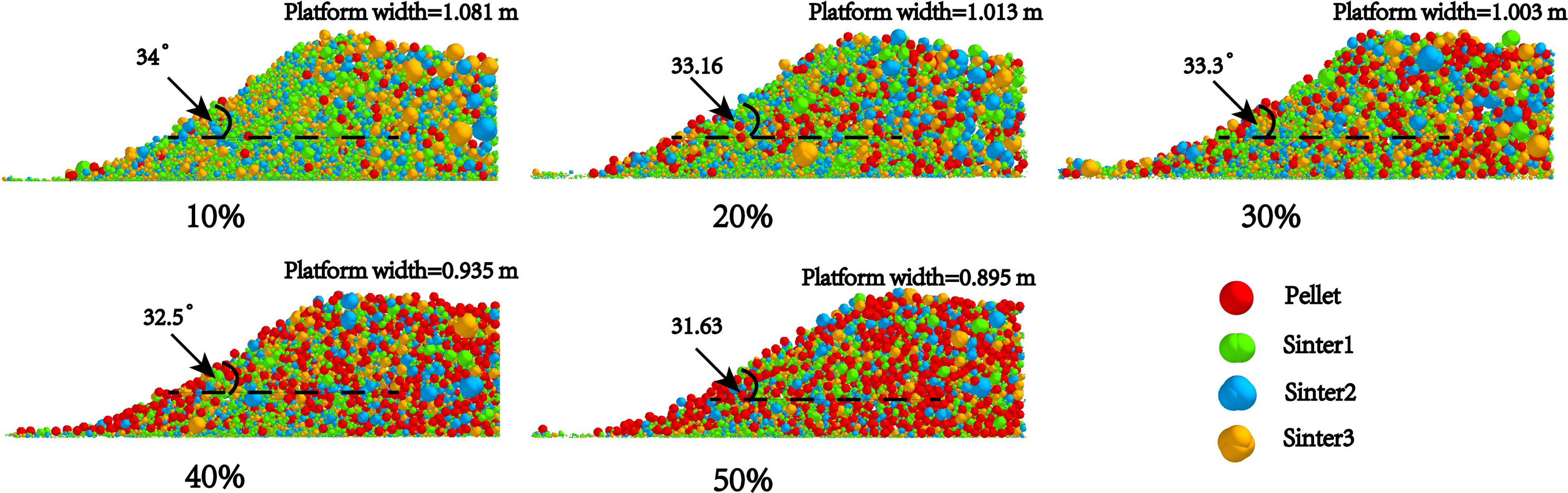
Distribution of burden with different pellet proportion.
Figure 10 shows the comparison of pile platforms and pile angles with different pellet proportions. Combined with Figure 9, it can be seen more intuitively that with the increase of pellet proportion, the pile platform and pile angle tend to decrease. This is because the rolling performance of pellet is stronger than that of sinter. With the increase in pellet proportion, the overall rolling performance of furnace charge also increases, resulting in the overall shift of the pile to the center.
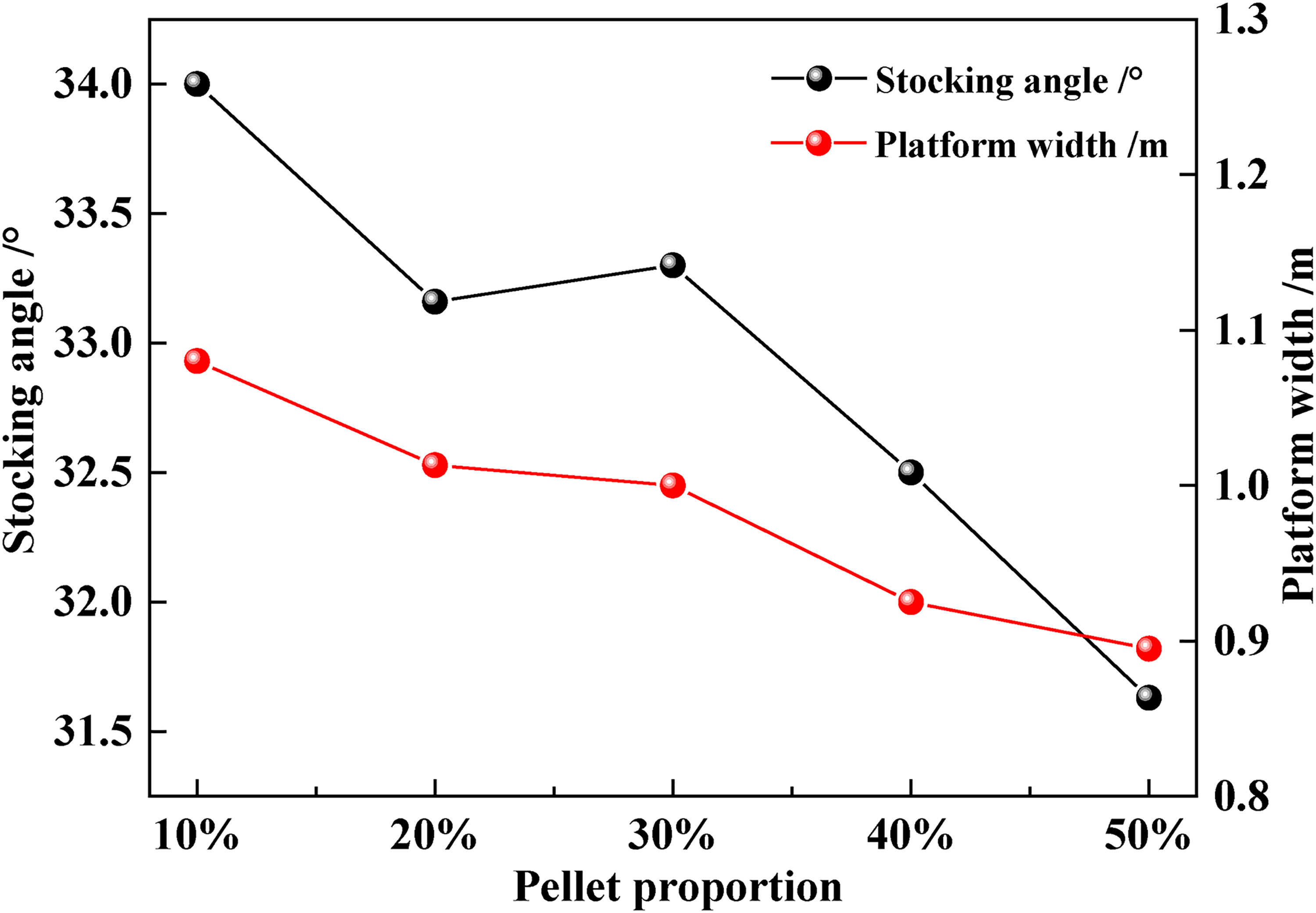
Stacking angle and platform width under different pellet proportion.
Analysis of segregation index
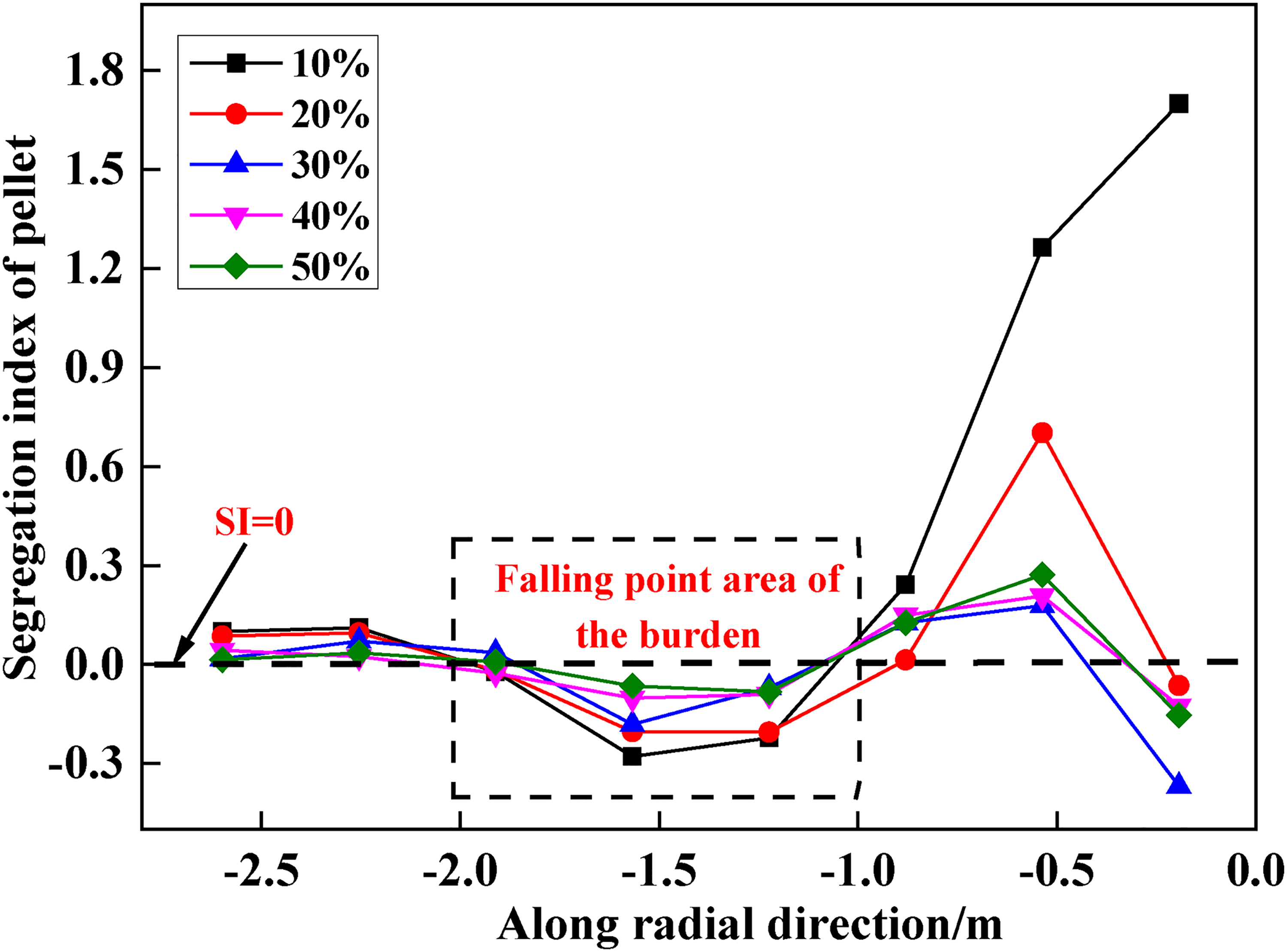
The segregation index is introduced to analyze the distribution of charge at different positions in the radial direction of furnace throat, which can provide guidance for the impact of charge segregation on the BF. Figure 11 shows the variation of segregation index of charge in the radial direction of stock surface with different pellet proportion. It can be seen that the segregation index near the furnace wall and the center of stock surface is greater than 0, while the segregation index of pellet at the falling point of charge is less than 0. As previously analyzed, when SI > 0, the proportion of pellets here is higher than the average level of pellets under this proportion. It shows that the pellet in the center of furnace throat and near the furnace wall is higher than the average level, while the proportion of pellet at the falling point of furnace charge is lower than the normal level. This is due to the rapid rolling of pellet, and the proportion rolling to both sides is large. Among them, due to the existence of furnace wall, the proportion of pellet rolling to the center is more.
Stacking angle and platform width under different proportion of pellets.
At the same time, it can be seen that the proportion of pellets in the monitoring area in the center of the charge level has decreased again. Combined with the distribution position of the stockline in Figure 9, it can be inferred that the segregation index near the center is >0 due to the existence of pellets, and the distance between the center of the furnace throat and the falling point of the charge is relatively far, so there is great contingency in the distribution of ores at this position. Moreover, the burden falls on the stockline, which makes its rolling performance worse, and the burden distribution in the center of the burden is less, so there are relatively few pellets falling here.
Effect of pellet proportion on porosity
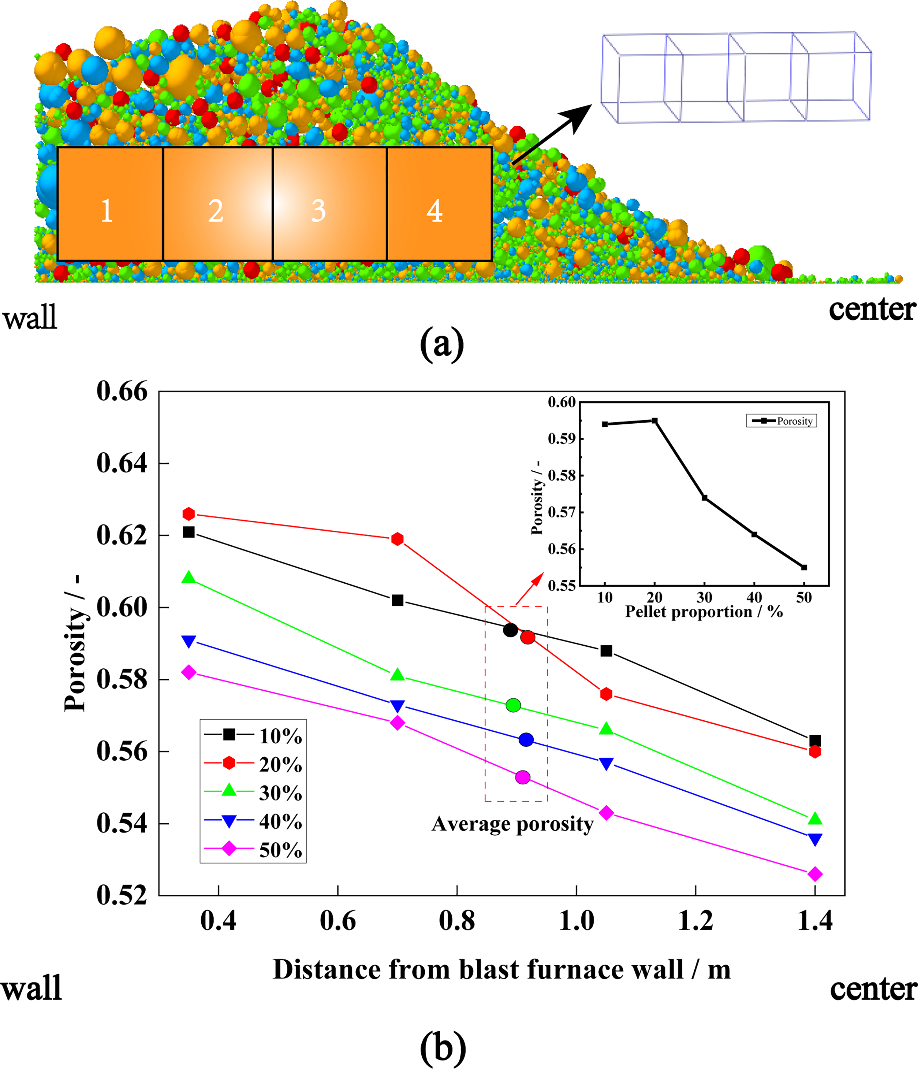
To investigate the effect of different pellet proportions on the permeability of the bed of material, the porosity of the stock column can be studied. According to the accumulation form of pellets with different proportions, four virtual volumes are established at the material pile along the radial direction of the furnace throat, as shown in Figure 12(a), and the changes in radial porosity of the furnace throat under different pellet proportions are monitored. Due to the problem of counting particles in the software, part of the particles contained in the virtual volume at the boundary will also be brought into the final calculation as a complete particle volume. Therefore, the calculated porosity value may be a little larger than the real value, but it has no effect on the change law of porosity caused by increasing the proportion of pellets. The proportion of pellets increases from 10% to 50%. The overall porosity of the stockline and its change from the furnace wall to the center are shown in Figure 12(b). It can be seen that the porosity of the stockline with different proportion of pellets decreases gradually from the furnace wall to the center. By comparing the average diameter of particles in different virtual volumes 1–4, it is found that the diameter of particles in area 1–4 decreases gradually, that is, the furnace charge with large particles is more concentrated at the furnace wall, so its porosity is relatively larger. It can also be seen from Figure 12(b) that with the increase in the proportion of pellets, the overall porosity of the material column will decrease, which is also consistent with the literature. 17 Therefore, in order to increase the proportion of pellets in the BF operation, its influence on burden structure and gas flow distribution should be considered.
Variation of the porosity of the stockline.
Conclusions
A DEM model of bell-less top charging system BF was established to investigate the effects of stock line level on charge accumulation, different pellet proportion on burden distribution at the end of chute, and the effect of different pellet proportions on burden distribution and porosity in the radial direction of furnace throat. The following conclusions could be drawn from the present study:
With the increase of the depth of the stock line level, the width of the material pile platform tends to decrease, while the stacking angle of the material pile tends to increase. Therefore, when adjusting the stock line parameters of the BF, it is necessary to fully consider the influence of the burden distribution matrix after adjusting the stock line on the condition of the BF. By monitoring the furnace charge at different positions at the end of the chute, it can be concluded that the furnace charge will be discharged preferentially from the middle of the chute. However, due to the inertia and rolling of the furnace charge, the furnace burden distribution at the end of the chute and the final distribution of the material level in the furnace throat cannot establish an effective relationship. As the proportion of pellets increases from 10% to 50%, the width of the stockline platform decreases from 1.081 m to 0.895 m, and the stockline angle decreases from 34.00° to 31.63°. With the increase in the proportion of pellets, the porosity of the stockline decreases, and the porosity also decreases gradually along the radial direction from the furnace wall to the center.
Footnotes
Acknowledgments
The authors gratefully acknowledge the financial support from the National Natural Science Foundation of China (grant number U1960205) and the State Key Laboratory of Advanced Metallurgy Fund Project at University of Science and Technology Beijing (grant number 41621021).
Declaration of conflicting interests
The authors declared no potential conflicts of interest with respect to the research, authorship, and/or publication of this article.
Funding
The authors received no financial support for the research, authorship, and/or publication of this article.