
Abstract
Introduction
Space closure is the most common treatment mechanic used in orthodontics in clinical practice. It can be done with friction and frictionless mechanics, and nowadays by using mini-implants. These mini-implants provide an absolute source of anchorage to obtain dental and soft tissue changes that are desired, thus helping to improve the patient’s profile.
Aims and Objectives
To evaluate the stress distribution patterns in the tooth, bone, and periodontal ligament in mini-implants placed at different heights and angulations for retraction and intrusion of maxillary incisors using finite element model (FEM).
Materials and Methods
FEMs of maxillary teeth and periodontal ligament housed in alveolar bone with the first premolars extracted were constructed. These models were further divided into two groups based on the number of implants. In group I, two implants were placed bilaterally between the second premolar and first molar at variable heights (7, 10, and 13 mm) and at different angulations (45° and 60°) to the long axis of the occlusal plane. In group II, along with the two bilateral mini-implants, an additional mid-implant was placed between two central incisors. These models were simulated using ANSYS 19.2 version software.
Results
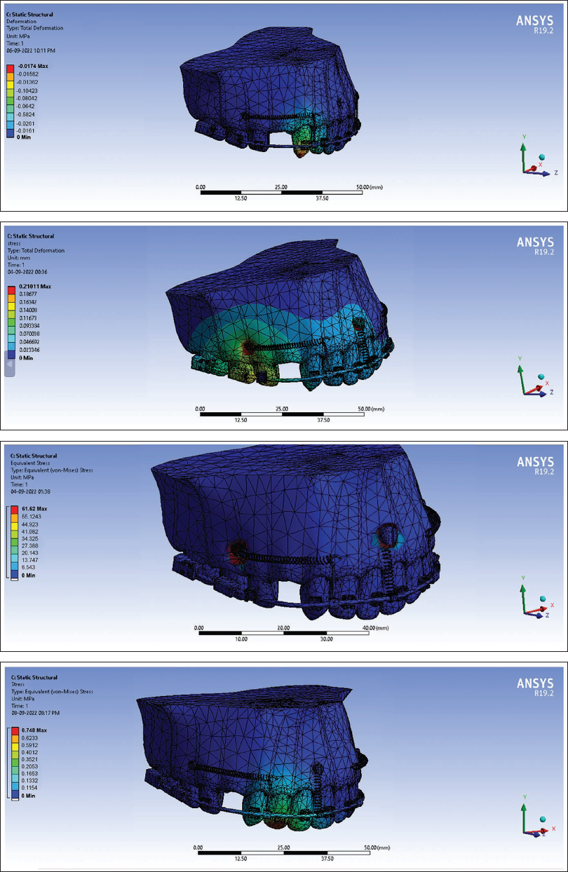
The maximum distribution of stress (MPa) in hard bone, soft bone, and implant was seen in the FEM 7 model and was 17.65, 0.210, and 61.62 MPa, respectively, during the retraction and intrusion of maxillary anterior teeth. The highest stress distribution (MPa) was seen in the lateral incisor tooth in FEM 7 model (0.748 MPa) and also in the periodontal ligament around the lateral incisor in FEM 7 model (0.684 MPa).
Conclusion
The stress distribution was found to be highest in the lateral incisor tooth, periodontal ligament of the lateral incisor, and hard bone. The stress distribution pattern showed variation with different heights and angulations of the mini-implant. As the angle of insertion of the mini-implant to the long axis of the occlusal plane increases, the stresses generated in the bone decrease.
Introduction
Dental protrusion is the most commonly encountered malocclusion which can be explained through dentoalveolar flaring of either maxillary anteriors, mandibular anteriors, or both, which results in protrusion of lips and facial convexity. The treatment involves extraction of the first premolars in both quadrants, and then retraction of the anterior segment was done with critical anchorage to obtain the desired dental and soft tissue changes. 1 The most challenging goal of orthodontic treatment is space closure, which can be done with friction or sliding mechanics and frictionless or loop mechanics. 2
Frictionless mechanics use loops and bends to generate the force to close the space site, which allows differential moments in both active and reactive units. 3 There are some drawbacks, such as complicated wire bending along with difficulty in measuring the delivered force and moment-to-force ratio, with patient non-compliance seen in frictionless mechanics, which results in less popularity of frictionless mechanics. On the other hand, friction mechanics involve the sliding of the brackets along the archwire and require minimal archwire bending. Commonly used methods for retraction in friction mechanics are elastomeric chains, power arms, and nickel-titanium (NiTi) closed coil springs. 4 The friction produced between the bracket and archwire leads to anchorage loss. Therefore, to counteract the shortcomings of friction and frictionless mechanics, clinicians use mini-implants which are also known as skeletal anchorage systems 5 (SAS).
Since the clinical significance of mini-implants is obstinated by the mechanical stresses that are transferred from mini-implants to bone and periodontal ligament (PDL), the quantification of these stresses under loading could be best analyzed using finite element analysis. It was used to calculate the tooth movement after applying force and proves to be a vital technique for simulating the pattern of orthodontic tooth movement.
As there is very limited literature available which had compared the different SAS for retraction with intrusion at different implant heights and angulations using finite element model (FEM), thus the aims and objectives of our study were to evaluate the stress distribution patterns in tooth, bone, and PDL in mini-implants placed at different heights and angulations for retraction and intrusion of maxillary incisors using FEM.
Materials and Methods
The study was conducted in the Department of Orthodontics and Dentofacial Orthopaedics and simulation of FEMs was done in Distt Solan, Himachal Pradesh. Ethical approval was acquired from the Institutional Research Ethical Committee (Vide No. hdc/ethical/Ortho/2020/16). The study included the designing of various FEMs of maxillary teeth and PDL within alveolar bone with the first premolar of both quadrants extracted, including variations in the number of mini-implants, heights, and angulations of placement of mini-implants.
Three-dimensional models of the maxillary central incisor, lateral incisor, canine, second premolar, and first molar were constructed using their dimensions and morphology. 6 The first premolar was not constructed, and an ovoid arch form was created. The maxillary dentition was arranged according to MBT norms so that mesiodistal angulations and labiolingual inclination of the teeth could be determined. The PDL was constructed with a thickness of 0.25 mm along with the alveolar bone around the roots of all the teeth. Brackets having a dimension of slot size 0.022″ × 0.028″ were made and attached to the labial surface of the crowns so that the facial axis point coincides with the center of the bracket slot. Then, the obtained geometric models were converted into FEM using elements and nodes.
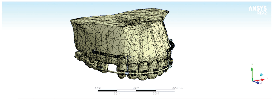
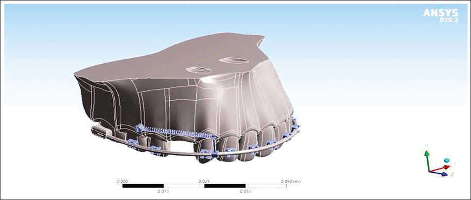
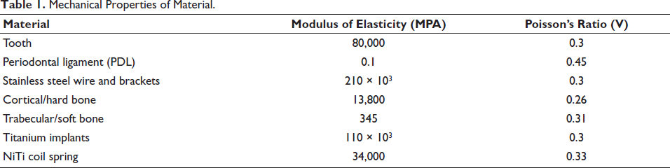
The FEMs were constructed from the DENTASCAN of the maxilla using SOLID WORKS 3D modeling software. The FEMs of the maxilla were constructed using ANSYS 19.2 software with their PDL space equal at 0.25 mm in all teeth as shown in Figures 1 and 2. These models were meshed using an automeshing routine using the mechanical properties of the material as shown in Table 1.
Constructed Three-dimensional Finite Element Model using ANSYS Software.
Three-dimensional Finite Element Model of Maxilla with Mini-implant, Anterior Retraction Hook, and Nickel-Titanium Closed Coil Spring.
Mechanical Properties of Material.
FEMs were divided into two groups:
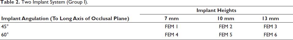
Group I: Two mini-implants were placed bilaterally between the second premolar and the first molar to the long axis of the occlusal plane as shown in Table 2.
Two Implant System (Group I).
Group II: An additional mid-mini-implant was placed between the two central incisors for intrusion at 12 mm from the archwire, along with bilateral mini-implants placed between the second premolar and the first molar along the long axis of the occlusal plane as shown in Table 3.
Three Implant System (Group II).
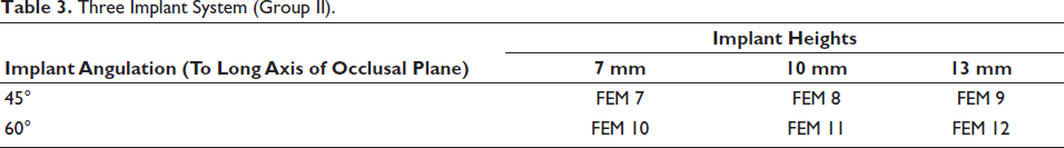
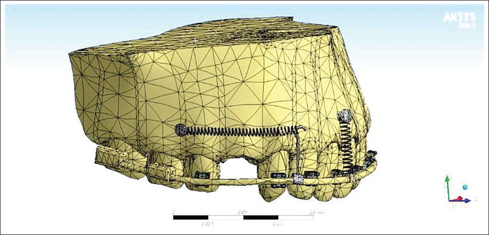
FEMs were constructed according to the placement of the mini-implants at different heights (7, 10, and 13 mm) and angulations (45° and 60°) in both groups. For retraction of the anterior teeth, the mini-implants (1.3 × 8 mm) were placed between the roots of the second premolars and first molars. An anterior retraction hook was placed between the canine, and a lateral bracket at 9 mm height from the archwire oriented gingivally was placed. A mid-mini-implant was placed constant at 12 mm from the archwire, perpendicular to the occlusal plane, between the two central incisors as shown in Figure 3. A NiTi closed coil spring was placed from the retraction hook to the mini-implant head, and a force of 120 g from bilateral mini-implants for retraction was provided. A force of 60 g was given from the mid-mini-implant to the archwire for the purpose of intrusion. The different FEMs were simulated, and the obtained values of stress distribution in the tooth, bone, and PDL were tabulated.
Three-dimensional Finite Element Model of Maxilla with Mini-implants, Mid-implant, Anterior Retraction Hook, and Nickel-Titanium Closed Coil Spring.
Results
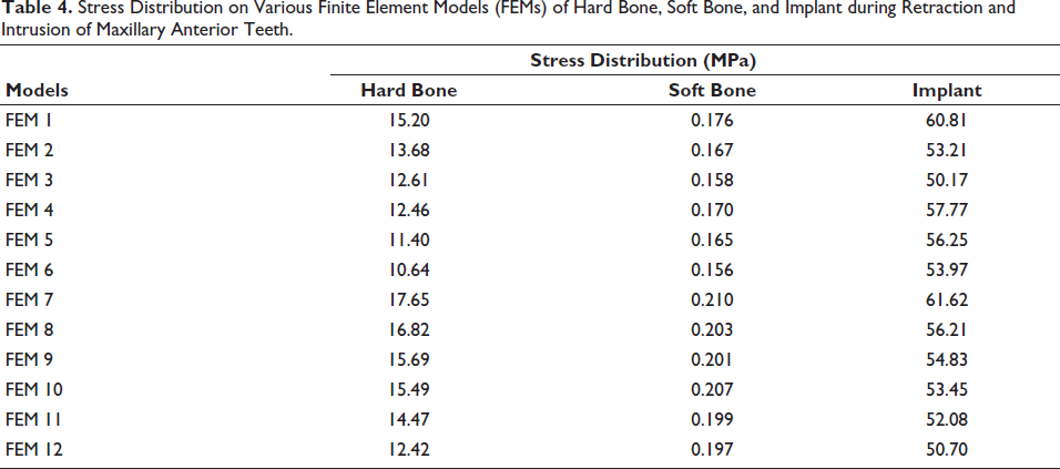
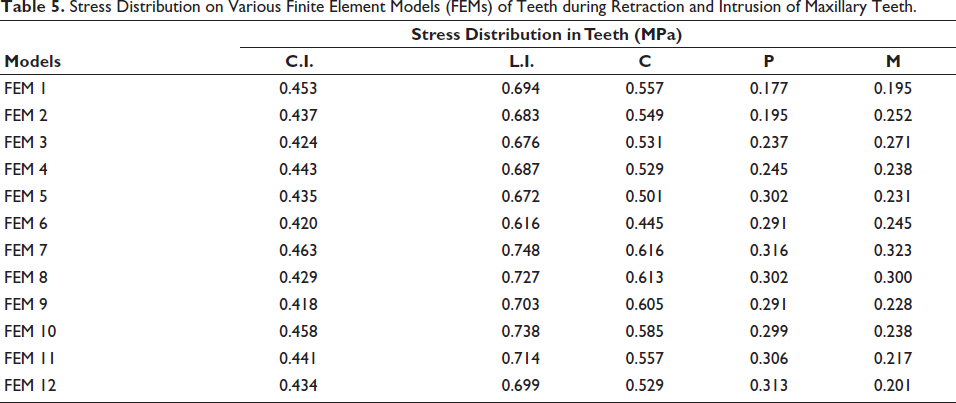
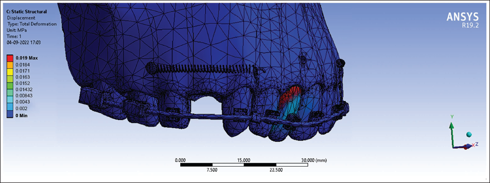
The stress distribution pattern during retraction and intrusion of maxillary incisors around hard bone, soft bone, and implant was highest in the FEM 7 model, and was found to be 17.65, 0.210, and 61.62 MPa, respectively, as shown in Table 4. The maximum stress distribution (MPa) on comparison of different teeth during retraction and intrusion of maxillary incisors was seen in the lateral incisor tooth in the FEM 7 model and was found to be 0.748 MPa as shown in Table 5. During comparisons of PDL of different teeth, the highest stress distribution was found in PDL around the lateral incisor tooth in the FEM 7 model (0.684 MPa) as shown in Table 6. The vertical displacement (mm) was found to be extrusive in the canine tooth in the FEM 1 model (–0.0174 mm) and intrusive vertical displacement in the lateral incisor tooth in the FEM 12 model (0.0149 mm) as shown in Table 7. The maximum anteroposterior displacement was seen in the FEM 2 model of central incisor teeth (0.019 mm) as shown in Table 8.
Stress Distribution on Various Finite Element Models (FEMs) of Hard Bone, Soft Bone, and Implant during Retraction and Intrusion of Maxillary Anterior Teeth.
Stress Distribution on Various Finite Element Models (FEMs) of Teeth during Retraction and Intrusion of Maxillary Teeth.
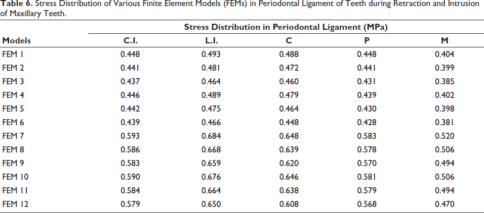
Stress Distribution of Various Finite Element Models (FEMs) in Periodontal Ligament of Teeth during Retraction and Intrusion of Maxillary Teeth.
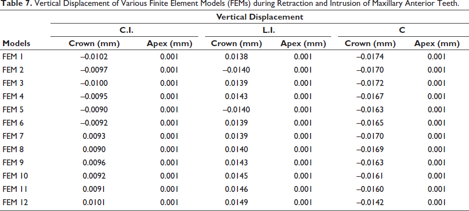
Vertical Displacement of Various Finite Element Models (FEMs) during Retraction and Intrusion of Maxillary Anterior Teeth.
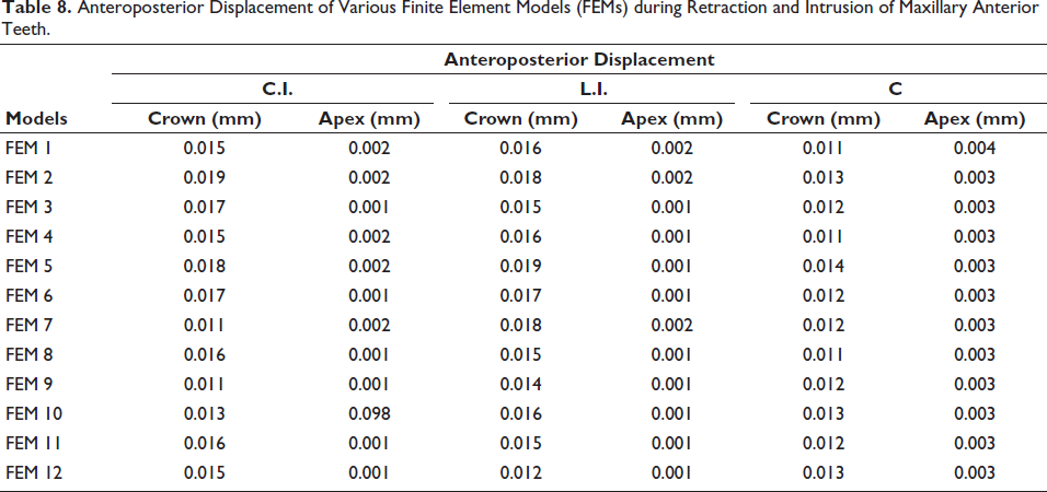
Anteroposterior Displacement of Various Finite Element Models (FEMs) during Retraction and Intrusion of Maxillary Anterior Teeth.
Discussion
The present study was done to assess the effects of stress distribution patterns in the tooth, bone, and PDL in mini-implants placed at varying heights and angulations for retraction and intrusion of maxillary incisors using FEM. In this study, 12 FEMs were constructed with a disparity in the number of mini-implants, height of placement, and with different force levels from the mid-implant.
On evaluating the stresses in the hard and soft bone at the mini-implant area, it was found that the stress generated was more in the FEM 7 model, that is, the low-pull implant (45° implant angulation with 7 mm height) as shown in Table 4 and Figure 4. This might be because low-pull implants produce more stress in the bone, as stresses in the bone decreased when the miniscrew height was increased, which was in accordance with the study done by Namburi et al. 1 Moreover, some parts of the threaded portion of the mini-implant were left unsupported by the bone due to less bone contact of the buccal surface as compared to the lingual surface of the mini-implant at a low insertion angle. As the insertion angle increases from 45° to 60°, the stress generation decreases around the implants, which was in accordance with Woodall et al. 7 and Zhang et al. 8
Finite Element Model (FEM 7) of Maxilla Representing Stress Distribution in Hard Bone, Soft Bone, Implant, and Tooth during Retraction and Intrusion of Maxillary Anterior Teeth.
Furthermore, the stresses generated on the soft bone were less as compared to the hard bone because the maximum stresses in the cortical bone were absorbed and minimal stress was transmitted to the cancellous bone, which was in accordance with the study done by Byoun et al. 9 and Jasmine et al. 10
On assessing the stress distribution of various FEMs on teeth during retraction and intrusion of maxillary anterior teeth at different angulations and heights, it was found that the stress generated was highest in the lateral incisor tooth in the FEM 7 model (0.748 MPa) as shown in Table 5 and Figure 5. This might be attributed to the smaller surface area and geometry of the lateral incisor, thus creating a substantial amount of stress in the cementum and PDL around it. Similar results were reported by the study conducted by Salehi et al. 11 and Vikram et al. 12
Finite Element Model (FEM 7) of Periodontal Ligament of Lateral Incisor Representing Maximum Stress Distribution during Retraction and Intrusion of Maxillary Anterior Teeth.
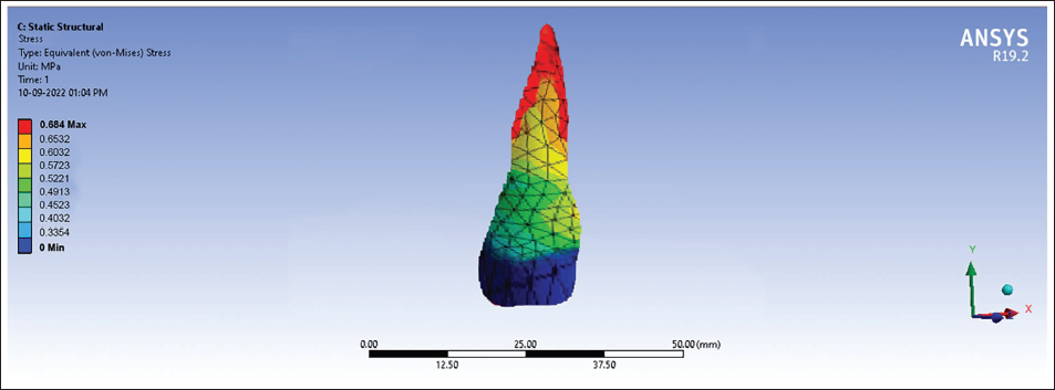
On assessing the stress distributions on PDL, it was found that the stress generated in the lateral incisor tooth during retraction and intrusion of maxillary anterior teeth at different angulations and heights was highest in the FEM 7 model (0.684 MPa) as shown in Table 6 and Figure 6. The reason for the highest stress generation in the lateral incisor might be because of its smaller root surface area, which produces more stress magnitude when force is applied. This was in accordance with the study done by Burstone and Viecilli. 13
Finite Element Models (FEM 1 and FEM 12) Representing Vertical Displacements during Retraction and Intrusion of Maxillary Anterior Teeth.
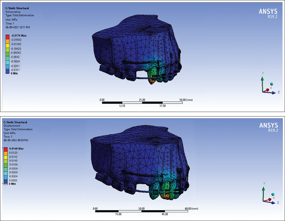
In vertical displacements, intrusion was seen in three-implant group compared to two-implant group. The line of action of force passing from the high-pull implant to the retraction hook will cause intrusion and from the medium-pull implants showed translation, whereas the low-pull implant showed extrusion. These results were in accordance with Ashekar et al. 14 The highest vertical displacement, that is, extrusion, was seen in the FEM 1 model (–0.0174 mm) as shown in Table 7 and Figure 7. This extrusive vertical displacement of canine might be due to the fact that implant height was 7 mm from the main archwire and the center of resistance of the FEM was found to be at 10 mm from the archwire, so the line of action of force was below the center of resistance, which could lead to extrusion of the teeth. These results were in harmony with the study done by Hedayati and Shomali 15 and Namburi et al. 1
Finite Element Model (FEM 2) Representing Anteroposterior Displacement during Retraction and Intrusion of Maxillary Anterior Teeth.
On further evaluation of the assessment of vertical displacement of various FEMs of the lateral incisor during retraction of maxillary anterior teeth, it was found that the highest vertical displacement was seen in FEM 12 model (0.0149 mm) as shown in Table 7. This intrusive vertical displacement of the lateral incisor might be because the implant height was 13 mm from the archwire in FEM 12 model. The center of resistance of the FEM was found to be at 10 mm from the archwire, as in this, the line of action of force was passing above the center of resistance, which leads to the intrusion of the teeth. Moreover, this intrusive force on the FEM 12 model could be due to the presence of a mid-implant between the two central incisors, which produces a vertical component of intrusive force. Similar results were reported by Bohara et al. 16 and Namburi et al., 1 suggesting that more intrusive forces were produced by implants placed above the center of resistance.
On assessing the anteroposterior displacement of various FEMs, it was found that the highest anteroposterior displacement was found in the FEM 2 model of central incisor teeth (0.019 mm) as shown in Table 8. This anteroposterior displacement in the FEM of central incisors was more due to the fact that at an implant height of 10 mm, the transverse component of force is near to the center of resistance of the anterior segment, which results in more bodily movement. This was in accordance with Bohara et al. 16 The force levels that are passing away from the center of resistance will cause tipping, thus having less anteroposterior displacement, and at or near to the center of resistance causes bodily movement, resulting in more anteroposterior displacement, which was proven correct in the present study.
Hence, it can be concluded from the study that the stress levels should be kept low to prevent failure of the mini-implant, with an increase in the angulation of the mini-implant from 45° to 60°. The stability of the mini-implant was found to be more with an increase in the insertion angle.
Conclusion
The stress distribution was found to be highest in the hard bone and PDL of the lateral incisor tooth.
The stress distribution pattern varied with the insertion angle and height of placement of the implant. As there is an increase in the angle of insertion of mini-implant, the stresses generated in the bone decrease. Therefore, low-pull implants produce more stresses in the hard bone.
Bodily movement will occur when the line of force application passes through the center of resistance of the maxillary anterior segment, and therefore the mid-implants show more of the anteroposterior displacement, and high-pull implants show more vertical displacement as compared to low-pull implants.
The overall evaluation showed that three-implant system showed higher stress distribution than two-implant system.
Footnotes
Declaration of Conflicting Interests
The authors declared no potential conflicts of interest with respect to the research, authorship, and/or publication of this article.
Ethical Approval
Ethical approval was acquired from the Institutional Research Ethical Committee (Vide No. hdc/ethical/Ortho/2020/16).
Funding
The authors received no financial support for the research, authorship, and/or publication of this article.
Informed Consent
Not applicable.