
Abstract
Orthodontic treatment commonly requires posted archwires for en-masse retraction, for attaching headgear and elastics. Prefabricated brass-posted archwires are popular, the main disadvantages being extended inventory and cost. Considering all these challenges, this new V-Jig has been introduced. The innovation of this jig allows freehand operation, with more precision of placement of posts on the archwire and reduces chances of loss of original wire properties. Soldering technique with jig is convenient and easy. It is a chairside apparatus to make posted archwire and other appliances with ease.
Introduction
Retraction mechanics is used in orthodontics for closure of extraction spaces, proclination correction, and overjet reduction. It also involves treatment strategies to prevent anchorage loss. For retraction, hooks are attached to the archwire either by soldering or crimping on the archwire. Retraction forces are then applied with hooks by using closed coil springs or elastomeric chain. 1 Although the process of crimping of hooks on archwires is less time consuming and easier for the clinician; however, they pose a problem of getting displaced along the archwire. This can be avoided by crimping the hooks with heavy force or by spot welding the hook to the wire. While crimping of the hooks, heavy force can distort the archwire and spot welding can result in annealing of the wire due to the heat produced along with the wire properties getting compromised.2, 3
There are two types of posted archwire, that is, brass-post soldered to stainless-steel archwire and crimpable hooks crimped on the archwire. The prefabricated brass-posted archwires are popular alternative choices for retraction but is not preferred by the clinician due to extended inventory and cost. 4 Furthermore, the crimpable archwire hooks are easy to use and convenient but can get displaced which may result in an unwanted force application on the archwire. Soldered-posted archwire can serve as a replacement to crimpable archwire hooks because of its secured attachment. It also provides an option for attaching headgear, elastics, and springs. It is advisable to use the strongest possible solder joint so that posts remain firmly attached to the archwire. Brass posts are commonly used as it is malleable for bending but will not break or kink. Posts are available from 22 mm to 44 mm in 2-mm increments. The height of posts usually measures 5.5 mm from wire to tip. It assures ample room for attachments. The position and angulation of the posts are critically dependent upon the treatment plan. It is also extremely important to not lose any original properties, dimensions of archwire while crimping or soldering. This New JIG is introduced to overcome all these challenges and to reduce chairside time, cost, and inventory.
Methodology
Materials and Methods
Armamentarium for fabrication of the posted archwires:
Arch wire positioning-stainless steel (SS) jig Flux Silver solder Brass wire SS archwire (0.019 × 0.025, 0.018 × 0.025, etc) Blow torch Marker Distal end cutter
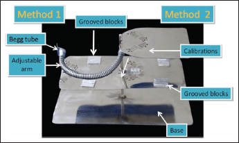
Parts of SS jig (Figure 1)
SS plate: the apparatus consists of three SS plates at different levels. Two different methods of manipulation of the posted archwire are possible because of the placement of the plates.
Adjustable arm: a movable arm is attached to the main body of the apparatus. It can move along the length of the device. It makes the manipulation process easy and comfortable.
Begg tube: Begg tube is soldered at the end of the movable arm. Brass wire is passed through it vertically.
Grooves: blocks are pregrooved for the upper and lower wire separately. It helps to stabilize the wire while soldering it as well as maintain archform of the wire.
Posted measurements: standard-posted archwire measurements marked on all SS plates. It is easy to solder the post at the desired position on the archwire.
Jig structure consists of base, Begg tube to hold the brass wire, adjustable arm to move the brass wire along the length of archwire, grooved blocks to stabilize archwire, and standard calibrations to mark and make posts.
Method to Use
Two methods can be used for soldering of a brass wire to the SS archwire:
Method 1 (Figure 2)
Stabilize the archwire with the help of pregrooved blocks located on the stainless-steel plate. The blocks are made such that upper and lower archwire can be stabilized without any deformation.
The Begg tube is soldered vertically to the adjustable/movable arm. Begg tube holds the brass wire in position and allows movement along the length of the archwire.
The liquid flux is applied to the arch wire at the desired position.
The silver solder is transferred on the SS archwire and heated with torch flame.
After heating, the joint is quenched immediately with water droplets in order to prevent annealing.
The brass wire (post) is cut at around 5 mm of height as per the requirement.
After disengaging the archwire from the jig, the soldered joint is polished and is ready for use.
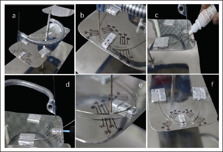
Method 1, stepwise procedure of making a posted archwire. (A) Stabilization of archwire on grooved blocks. (B) Placement of brass wire according to the precalibrated markings to make post. (C) Application of flux. (D) Soldering with silver alloy. (E) and (F) Cutting of excess brass wire and making a customized posted archwire.
Method 2 (Figure 3)
In this method, two steel plates, that is, upper and middle, are used from the apparatus.
On the upper plate, laser holes are made according to standard sizes of the brass wire.
On the lower plate, the archwire is stabilized using pregrooved blocks.
The arrangement is made such that when the brass wire is suspended from the preformed holes of the upper plate, it contacts at the same site as calibrations for the post (Figure 2a).
Further steps are same as method 1.
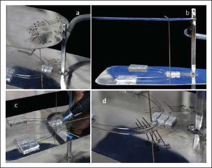
Method 2, stepwise procedure of making a posted archwire. (A) Stabilization of archwire on grooved blocks and brass wire is dropped from first stainless steel plate on second. Placement of brass wire is according to the precalibrated markings to make post. (B) Brass wire stabilizes on the archwire without movable arm. (C) Application of flux and soldering with silver alloy. (D) Cutting of excess brass wire and making of customised posted archwire.
Discussion
During orthodontic treatment, posted archwires are common modalities used for en-masse retraction, engaging elastics and so on. With this kind of jig, hands-free operation is possible which will reduce chairside time. The chances of annealing of the archwire are decreased as the precision level increases with the use of jig.
Furthermore, soldering with jig has numerous advantages including increased precision as compared to freehand soldering. It is less sensitive to hand movement which adds to the accuracy even reducing manual efforts. Since the apparatus is portable, it allows one to manipulate the archwire anywhere and makes it easier to handle. Quality isn’t affected even when reproduced multiple times. Jig is versatile enough for soldering according to use of different appliances.
It allows the usage of silver solder, strongest possible solder for increased durability and strength. Soldering methods could even alter metal release in the oral environment as their levels are insignificant.
Other uses of the jig:
Space maintainer fabrication in mixed dentition patients
Soldering Adam’s clasps to the appliances
In orthognathic surgeries during the presurgical phase soldering of multiple posts
Any modification in retention plates requiring a soldering procedure
Conclusion
Soldering technique with jig and moving arm is a very convenient chairside apparatus to fabricate posted archwire. It can be seen as a futuristic approach in orthodontics and can be used in clinical practice with great ease.
Footnotes
Declaration of Conflicting Interests
The authors declared no potential conflicts of interest with respect to the research, authorship, and/or publication of this article.
Funding
The authors received no financial support for the research, authorship, and/or publication of this article.
Statement of Informed Consent and Ethical Approval
Necessary ethical clearances and informed consent was received and obtained respectively before initiating the study from all participants.