
Abstract
Objective:
To measure and compare bracket transfer accuracy of 3 indirect bonding (IDB) techniques.
Material and Methods:
Three IDB techniques were studied using polyvinyl siloxane (PVS) putty, vacuum-form (VF), and glue gun (GG). A total of 120 orthodontic stone models were fabricated with die stone, out of which bonding was done on 60 working models and transferred to other 60 patient models. One quadrant was selected for each technique. Digital photography was used to measure the mesiodistal (X-axis), occlusogingival (Y-axis), and faciolingual (Z-axis) position of each bracket on the working and patient models.
Results:
All the 3 IDB techniques have a very good bracket transfer accuracy. On comparing individual planes, greatest accuracy was seen in GG on X-axis, VF on Y-axis, and VF/PVS on Z-axis. Points A and B were compared for bracket rotation and the mean differences were insignificant indicating that there was no significant amount of rotation in 3 IDB techniques.
Conclusions:
We can say that all 3 IDB techniques had a very high bracket transfer accuracy.
Out of the 3 IDB techniques VF was the most accurate, whereas PVS was the least accurate technique. The selection of technique should be based on tray cost and fabrication time.
Keywords
Introduction
Accurate bracket placement is essential for effective and efficient orthodontic treatment. 1 Base adaptation, rotational position, vertical position, and slot angulations are the components that demand attention while bracket positioning. 2
Direct bonding is the commonly used technique for orthodontic bracket placement. There are some limitations with this technique such as poor visualization of posterior teeth, decreased access to surfaces of malposed teeth, increased chair side time, and higher chances of moisture contamination. 3 Improper positioning of a bracket can result in rotation, tipping, in/out, extrusion/intrusion, and torque. 4 Indirect bonding (IDB) technique was first published by Silverman et al 5 in 1972. In IDB technique, brackets are first positioned on dental casts and then transferred to the patient’s teeth. 4 It has better 3-dimensional visualization of teeth which gives higher accuracy in bracket positioning, particularly in the posterior segments.3, 6, 7 IDB has subsequently increased in popularity due to unimpaired visibility during bracket positioning, improved patient comfort, and reduced chair side time. 8
According to Aguirre et al, 9 there was no significant change in the angulation and vertical position of maxillary and mandibular canine brackets in IDB, whereas mandibular second premolars had more accuracy in direct bonding.
Koo et al 10 found that both direct and IDB techniques did not have ideal bracket placement, but IDB technique had a better vertical placement of brackets. Hodge et al 11 assessed the bracket positions in vertical, horizontal, and angular aspects and concluded that the discrepancy was greater for direct bonding than IDB in all 3 aspects, thus proving that the envelope of error was reduced by IDB techniques.
The IDB procedures can be divided into many types depending upon the type of trays (eg, silicone, thermal glue, and rapid prototyped), type of adhesion systems (eg, light cure, chemical cure, and dual cure), or type of bracket-positioning guides (eg, slot heights and slot angulation) used. 12 The materials we included in this study are polyvinyl siloxane (PVS) tray, single vacuum-form (single-VF), and glue gun (GG). We chose these materials as they are economical, easily available, and do not demand much equipment and lab assistance. Majority of the studies have compared the efficiency of direct bonding and IDB techniques,4, 9-11 but only few studies have compared various IDB techniques.8, 18
The aim of the current study was to measure and compare bracket transfer accuracy of 3 IDB techniques using light-cured resin. Also, to check the amount of bracket rotation seen in all 3 IDB techniques.
Materials and Methods
The IDB techniques were performed on a stone model by using PVS tray (3M ESPE Soft Putty), single-VF (Scheu Bioplastic 1 mm, Scheu Dental GmbH, Iserlohn, Germany) and GG (K999 Model No. XL-F).
Working and Patient Stone Models
Quadrants were assigned for each material as follows: maxillary right quadrant for PVS tray, maxillary left quadrant for VF, and mandibular right quadrant for GG.
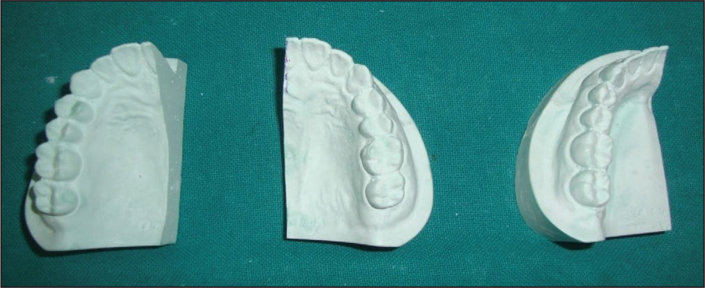
Ideal maxillary and mandibular model were cut into half and taken as master model (Figure 1).
Ideal Maxillary and Mandibular Model Were Cut into Half Which Served as Master Model for Each IDB Method.
Single-VF sheet was used to prepare molds from the respective master model. From the molds, a total 120 orthodontic stone models were fabricated with die stone, and careful trimming and filling of small voids was done 13 (Orthocal die stone Type IV, ISO 9001:2008, MAARC), out of which bonding was done on 60 working models and transferred to other 60 patient models. Twenty “working models” and 20 “patient models” were included in each technique.
Indirect Bonding Technique
Two coatings of separating media (Al-Cote® Separating Agent, Dentsply Sirona Prosthetics, York, PA) were applied to the working models and dried. 13 Standard edgewise brackets (Centrino Bracket Kit–CE22K) with a 0.022-inch slot were bonded 14 with light-cured resin (Transbond XT, 3M Unitek, Neuss, Germany) on central incisor (CI), lateral incisor (LI), canines (Cs), first premolar (PM1), and second premolar (PM2).
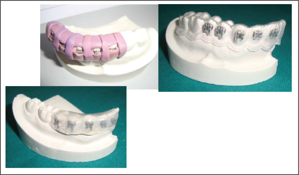
After bonding, fabrication of trays was carried out on these working models using PVS 15 (3M ESPE Soft Putty), single-VF 16 (Scheu bioclast 1 mm, Scheu Dental GmbH, Iserlohn, Germany) and GG 17 (K999 Model No. XL-F) (Figure 2).
(A) Polyvinyl Siloxane (PVS) Tray (DAS’s Occlusal Window); (B) Vaccum-Form (VF) Tray; (C) Glue Gun (GG) Tray.
All trays were fabricated so as to cover the facial, occlusal, and at least half of the lingual surfaces. 8 DAS technique 15 was used for PVS. This bracket transfer tray is designed in such a way that the excess composite flash during indirect bracket bonding is pushed in the incisal and occlusal direction only so that it can easily be removed by rotary instruments. Furthermore, it has the occlusal and incisal stops for accurate positioning of the tray on to the dentition. Other advantages of this tray system are better moisture control, easy removal of tray, and ease of fabricating the tray. A notable disadvantage of this tray system is the lack of rigidity. 15 After removal of these trays bearing the brackets, a thin layer of model adhesive (cyanoacrylate glue) was applied to each bracket. Subsequently, each tray was seated uniformly on the patientmodel and secured by applying firm pressure parallel to the occlusal plane by the investigator’s right hand. After the adhesive was set, trays were cautiously removed from lingual side followed by the buccal leaving the brackets adhered to the patientmodel. This bonding agent served the purpose of adhesion of the brackets to the patient models.
Photographic Measurements
The photographs of all teeth with brackets were captured using a Nikon DSLR D5200 (Nikon, Tokyo Japan) camera with a zoom lens (18–140 mm) set on manual mode with F-stop of 40 at 1:60 of a second on working as well as patient models. The position of the tripod was fixed on which the camera was placed, and the lens was adjusted on the jig to ensure standardization of the images. With the help of a custom-made tooth positioner, the models were placed on the calibrated graph paper (one for each master model), which was fabricated in such a way that the facial surface of every tooth was placed at the center of the camera lens and parallel to it (Figure 3).
Mesiodistal (X-axis), occlusogingival (Y-axis), and faciolingual (Z-axis) measurements for each bracket were measured using Adobe Photoshop Elements 10 (Adobe Systems Inc, San Jose, Calif). A magnification of 8.5× and JPEG images of 300 × 300 DPI were used. A software-constructed grid with 1.00 mm calibration was superimposed on the photographed images.
Mesiodistal (X-axis) and Occlusogingival (Y-axis) Measurements
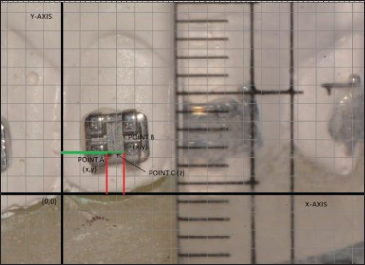
The horizontal reference line (X-axis) was taken passing through incisal edge in anteriors and cuspal tip in posteriors, whereas vertical reference line (Y-axis) was taken as a line passing through the interdental contact and center of interdental papilla for each bracket. The image was adjusted in such a way that X-axis and Y-axis coincided with horizontal as well as vertical lines of the grid for better calibration ease of measurement (Figure 4). Point A was selected on the inner side of the mesial tie wing, and Point B was selected on the inner side of distal tie wing on the intersection of the occlusal edge of the of the scribe line base with mesial and distal tie wings. X- and Y-coordinate values were measured for both points A and B to the nearest values of 0.01 mm. These values were measured thrice consecutively and the average of the three measurements was recorded.
Points A and B Were Used for Measurement in Mesiodistal (X-axis) and Occlusogingival (Y-axis), With Constructed Origin and Grid.
Faciolingual (Z-axis) Measurements
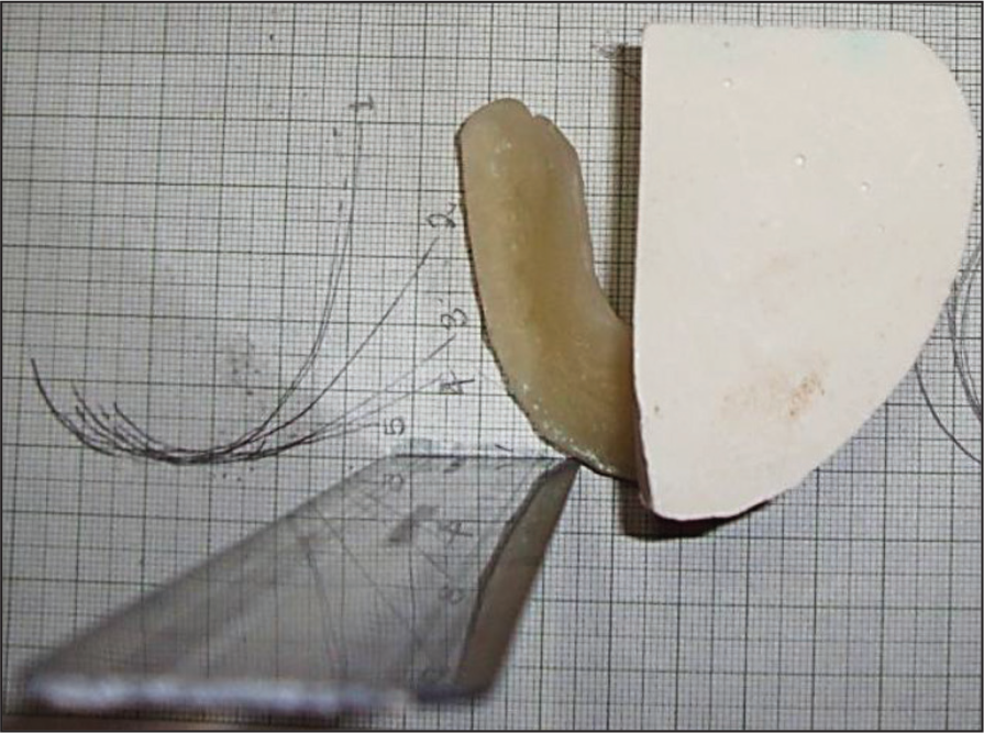
Line passing through interdental contact area of 2 CIs in midsagittal plane is termed “Z1” and line passing through interdental contact area of PM2 and first molar in transverse plane perpendicular to Z1 is termed “Z2.” Point of intersection of Z1 and Z2 is termed point “Z” (Figure 5).
Faciolingual Measurement from Point C to Z on Each Tooth.
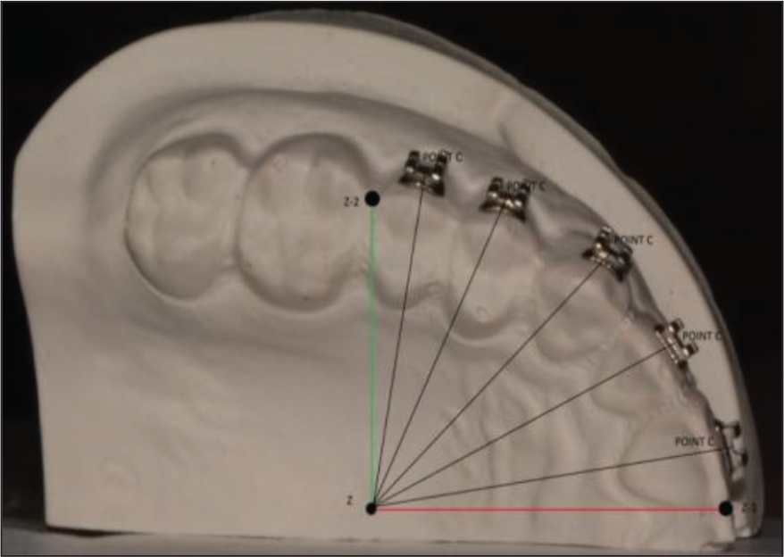
Point (C) was selected at the base of scribe line toward the occlusal edge. Distance was measured from point C to Z-axis. These values were measured thrice consecutively and the average of the three measurements was recorded. This study extended up to a period of 5 months.
Sample size for this study was calculated from Open Epi, Version 3, open source calculator—SS Mean using the formula n = (σ1 2 + σ2 2 ) (Z1− α /2 + Z1− β )/∇ 2 where Z represents the two-sided Z value for 95% confidence interval which is equal to 1.96; σ1 and σ2 represent the standard deviation of groups 1 and 2, respectively; and ∇ represents the difference in group means. The power was set at 80%. The sample size was estimated at 498 observations for 1 technique. We took 500 observations (PVS/VF/GG-500 Table 1 and 2); hence, the total sample size was 1500. The sample size distribution according to techniques, axes, point, and tooth is represented in Figure 6.
Distribution of Sample Size According to (Outward) Technique, Axes, Points, and Teeth.
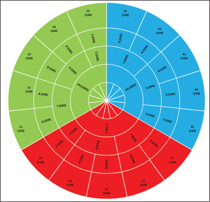
Technique-Wise Distribution.
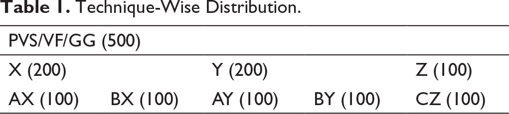
Tooth-Wise Distribution.
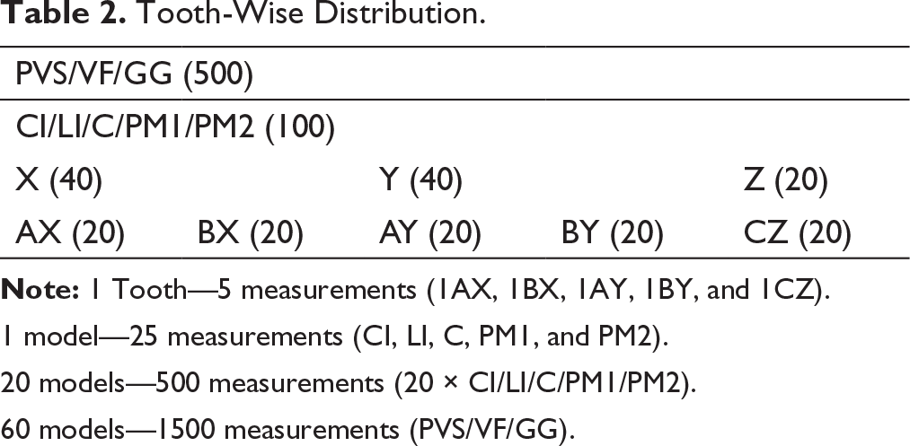
1 model—25 measurements (CI, LI, C, PM1, and PM2).
20 models—500 measurements (20 × CI/LI/C/PM1/PM2).
60 models—1500 measurements (PVS/VF/GG).
Statistical Analysis
SPSS version 16 was used to conduct the statistical analysis. One examiner performed all the measurements. To estimate the reliability of the method, 40 randomly selected models (20 working models and 20 patient models) were re-evaluated. The intraclass correlation coefficient (ICC) showed high reliability with value of 0.91. Data normality was assessed by Kolmogorov–Smirnov test, and the distribution was found to be normal.
The bracket transfer accuracy was assessed by calculating the mean differences between the working and the patient models for each tooth. Analysis of variance (ANOVA) was used to compare bracket transfer accuracy for all 3 techniques as well as for every individual direction, point, and tooth. Post hoc Tukey honestly significant difference (HSD) test was used for within-group comparison of the mean differences. The significance was set at P < .05
Results
Technique
Descriptive of Various Components of IDB Technique.
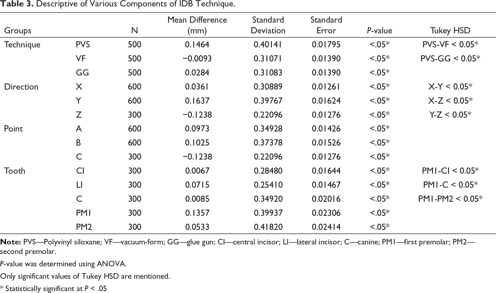
P-value was determined using ANOVA.
Only significant values of Tukey HSD are mentioned.
* Statistically significant at P < .05
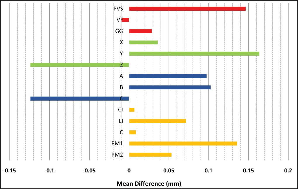
Mean Difference (mm) of Various Components of IDB Technique.
Direction
Bracket Transfer Accuracy of PVS, VF, and GG on X, Y, and Z Axes.
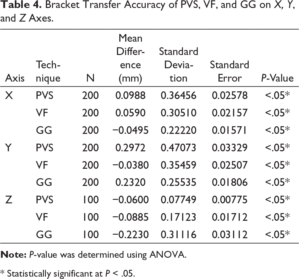
* Statistically significant at P < .05.
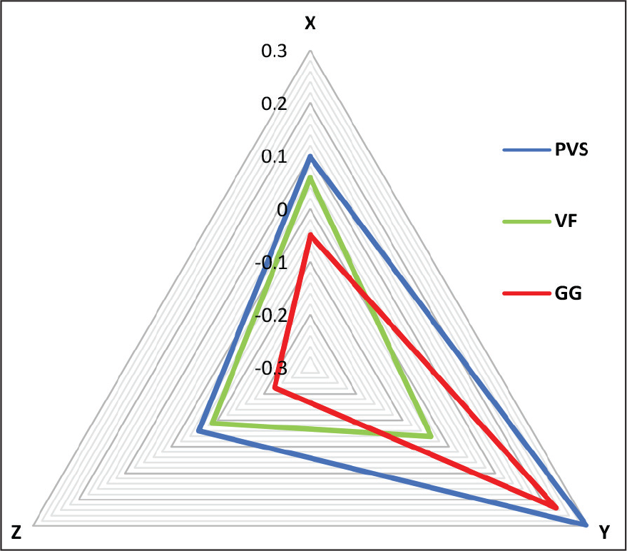
Comparison of Mean Differences (mm) in Bracket Position Among the 3 Methods on X-axis, Y-axis, and Z-axis. PVS, Polyvinyl siloxane; VF, vacuum form; GG, glue gun.
Point
Points A, B, and C had significant (P < .05) results for all 3 techniques (Table 3 and Figure 7) and on applying Tukey HSD to check for bracket rotation, there was no significant difference between the points A and B (P = .962).
Tooth
The results were significant for CI, LI, C, PM1, and PM2 (P < .05) for all 3 techniques (Table 3 and Figure 7), and Tukey HSD showed that there was a significant difference between PM1 and CI, C, and PM2 (P < .05).
Discussion
The IDB procedure can be completed by using entire tray or by sectioning the tray into 2 or 3 segments. The degree of isolation that is possible and ease of tray placement are the determining factors for the sectioning of trays. 7 The method we used in this study was segmental IDB, which is performed routinely in the clinical setup, and by cutting the cast into half, we rendered judicious and efficient use of Orthocal die stone.
In our study, the IDB techniques were performed on stone model by using PVS tray, single-VF, and GG. The mean differences for PVS, GG, and VF were 0.1464 mm, 0.0284 mm, and ɽ0.0093 mm (Table 3), respectively, which shows that all 3 IDB techniques had a very good bracket transfer accuracy (Figure 7). The post hoc test gave no significant difference between VF and GG (P = .193) indicating that the bracket transfer accuracy is similar between theses 2 techniques, whereas there was a significant difference between PVS and VF/GG (P = .00) indicating that VF and GG had a better bracket transfer accuracy as compared to that of PVS. In contrast, the results obtained in the studies done by Castilla et al 3 and Dorfer et al 18 PVS had higher bracket transfer accuracy as compared to single-VF. Möhlhenrich et al 19 and Schmid et al 20 also concluded a similar result with highest linear discrepancy with PVS-VF and least with double PVS.
The X (mesiodistal), Y (occlusoginigival), and Z (faciolingual) axes had significant mean differences of 0.0361 mm, 0.1637 mm, and ɽ0.1238 mm (Table 1), respectively. An in vivo study conducted by Agarwal et al 21 showed that the vertical discrepancy (Y-axis) for CI (DB: 0.5268 mm, IDB: 0.2620 mm) and LI/C (DB: 0.5332 mm, IDB: 0.2088) was much greater than our value of 0.1637 mm, and the horizontal discrepancy (X-axis) for CI (DB: 0.5648 mm, IDB: 0.2084 mm) and LI/C (DB: 0.5828 mm, IDB: 0.2088) was also greater than our value of 0.0361 mm. Also, the comparisons between the 3 axes by Tukey HSD showed that the bracket transfer accuracy was the best on X (mesiodistal) axis followed by Z (faciolingual) axis, and then the Y (occlusogingival axis) with a P-value < .05. These results were in accordance with the study done by Schmid et al 20 in which the biggest error in the linear variables occurred in the vertical dimension followed by the transversal and the horizontal dimensions with both methods.
According to randomised clinical trial (RCT) done by Hodge et al, 11 the vertical discrepancy (Y-axis) was ɽ0.027 mm (DB) and ɽ0.20 mm (IDB) and the horizontal discrepancy (X-axis) was ɽ0.11 mm (DB) and ɽ0.05 mm (IDB). We have also measured the discrepancy caused due to alteration in the thickness (Z-axis) of the bonding agent, which was ɽ0.1238 mm, indicating that the thickness of the bonding agent was more on the working models as compared to that of the patient models. In our study, we have used light-curing method to avoid the air inclusions produced by uneven rate of polymerization of the chemically cured resins. 22
Furthermore, when we compared all 3 techniques on X, Y, and Z axes (Table 4 and Figure 8), the following results were obtained:
Order of bracket transfer accuracy on X-axis: GG > PVS/VF
Order of bracket transfer accuracy on Y-axis: VF > PVS/GG
Order of bracket transfer accuracy on Z-axis: VF/PVS > GG.
On X axis, PVS and VF had a similar bracket transfer accuracy (P = .389); on Y axis, PVS and GG had a similar bracket transfer accuracy (P = .184); and on Z axis, PVS and VF had a similar bracket transfer accuracy (P = .603).
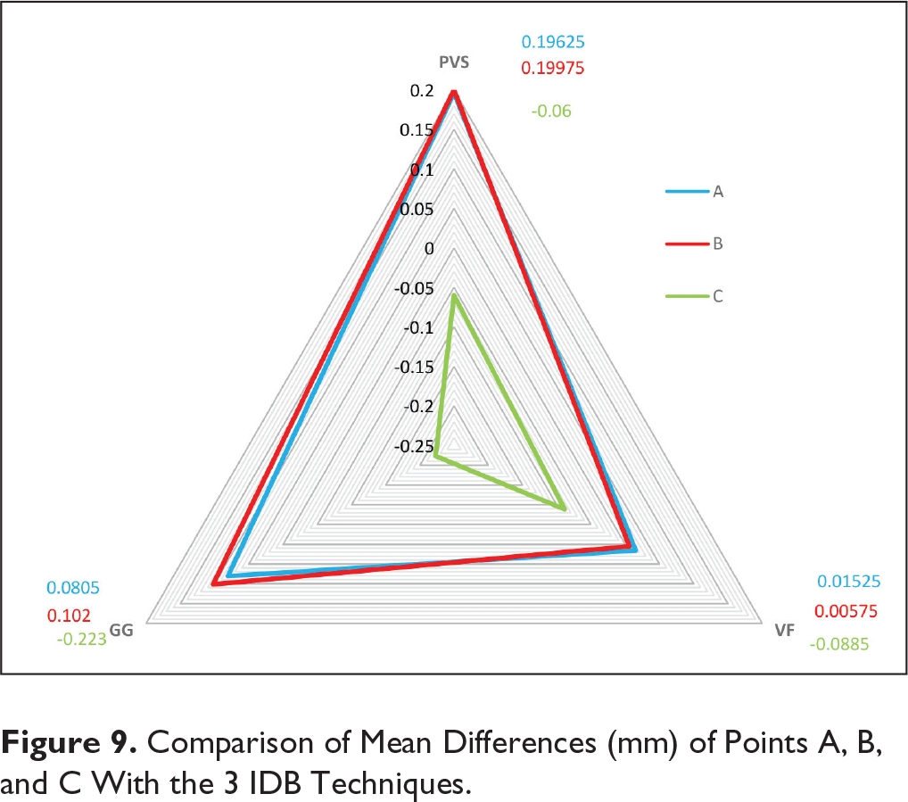
To check the rotation of brackets, mean differences of points A and B were assessed. When assessed separately, mean differences of points A and B were statistically significant (P < .05), but when the post hoc test was applied, there was no statistically significant difference between the points A and B (P = .962), indicating that there was no significant amount of rotation in all 3 IDB techniques. The comparison of mean differences of points A, B, and C with the 3 IDB techniques is shown in Figure 9.
Comparison of Mean Differences (mm) of Points A, B, and C With the 3 IDB Techniques.
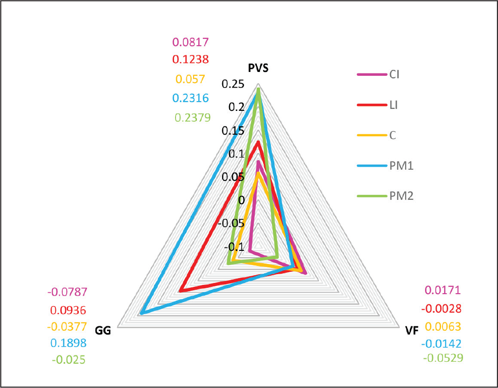
The mean differences of CI (0.0067 mm), LI (0.0715 mm), C (0.0085 mm), PM1 (0.1357 mm), and PM2 (0.0533 mm) were statistically significant indicating that the bracket transfer accuracy was very good for all the teeth included in our study. Further comparison between the teeth with Tukey HSD showed that the bracket transfer accuracy for PM1 was less as compared to CI/LI/C/PM2 (P < .05). The comparison of mean differences of CI, LI, C, PM1, and PM2 with the 3 IDB techniques is shown in Figure 10. Our result was similar to the study conducted by Schmid et al, 20 in which the comparison by tooth shapes showed that most inaccuracies were found in the premolar region for double-vacuum form trays for all directions.
Comparison of Mean Differences (mm) of CI, LI, C, PM1, and PM2 With the 3 IDB Techniques. CI, Central incisor; LI, lateral incisor; C, canine; PM1, 1st premolar; PM2, 2nd premolar.
The time required for the fabrication of GG tray was approximately 3 min (quickest), whereas for PVS tray, it was 15 min (longest). This may be because of the design fabricated according to DAS technique. A notable disadvantage of this tray system is the lack of rigidity.
In this study, we used an ideal model to measure the bracket transfer accuracy, but the patients would have a crowded dental arch with rotations. Hence, there might be a difference in the results since the materials might respond in a different manner to such clinical situations.
Further in vivo studies should be conducted to assess the bracket transfer accuracy of IDB techniques using FEM.
Conclusion
We can say that all 3 IDB techniques had a very high bracket transfer accuracy.
Out of the three IDB techniques, VF was the most accurate technique and GG did not show a significant difference when compared with VF, whereas PVS was the least accurate among the three techniques.
The horizontal discrepancy was the least among the 3 IDB techniques, whereas the vertical discrepancy was the most.
There was no bracket rotation seen in any of the three IDB techniques.
The bracket transfer accuracy was similar for CI, LI, C, and PM2 except for PM1 which had the lowest bracket transfer accuracy.
Since all the techniques are statistically significant, the tray cost and fabrication time should be considered while selecting any of the 3 IDB techniques.
Footnotes
Declaration of Conflicting Interests
The authors declared no potential conflicts of interest with respect to the research, authorship, and/or publication of this article.
Funding
The authors received no financial support for the research, authorship, and/or publication of this article.
Statement of Informed Consent and Ethical Approval
Necessary ethical clearances and informed consent was received and obtained respectively before initiating the study from all participants.