
Abstract
An innovative auxiliary spring design is presented to provide space creation in various clinical situations. Accompanied with a further innovative method of activation, it shall also limit the reciprocal movements of adjacent mesial teeth.
Introduction
Space creation during orthodontic treatment for alignment of irregularly accommodated teeth has been accomplished in a number of ways since the inception of orthodontics. The use of multiple loop wires, as an initial space provider, is still a cherished method in orthodontic alignment.1, 2 These wires paved way for and inspired the clinicians worldwide for the development of newer and simpler methods of space creation, particularly sectional springs, open-coil springs, and protraction auxiliary.3, 4 The following text is a brief introduction to an innovative spring design which functions as a sectional auxiliary for space creation in numerous clinical situations. In this design, placement and removal are easy for an adequately flexible spring, low forces are applied, and controlled multiple activations are possible. While most space-creating methods available at present are involved with either complicated methods of auxiliary placement and/or removal of the base arch wire itself, an advantage of this spring design is that the removal of the base arch wire becomes unobligatory at every activation appointment. The spring is accompanied with a further innovative method of activation which shall limit the reciprocal movements of adjacent mesial teeth.
Spring Design
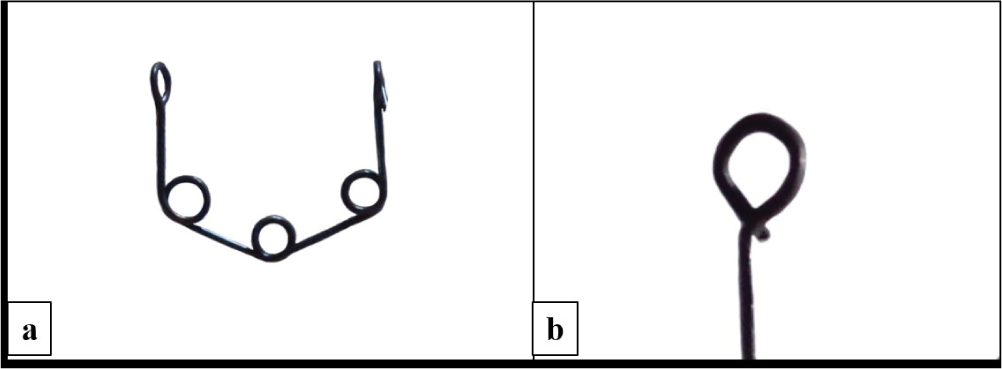
In this design, 0.016″ AJW/stainless steel wire is prepared into a trihelix formation (Figure 1(a)) such that the vertical legs are 5 mm in length and the horizontal/slanting legs are 5 mm in length. The length of the slanting legs could be varied (increased/decreased) according to the clinical situation in such a way that the effective vertical length of the spring is up to 8 mm. The spring extends around 5 mm beyond the gingival margin. Uneven, particularly inflamed gingival margins and alveolar mucosae require slight adjustment bends in the vertical arms near the hook area for an uneventful spring insertion and maintenance at place; furthermore, minimal coverage provides an additional advantage over other space-opening methods, such as a simple open-coil spring, frequently used by clinicians through lessened food lodging and better cleaning. Hooks at the free ends of the spring are fabricated as shown in Figure 1(b). Stainless steel spring should be heat treated after fabrication for the release of stresses.
(a ) Smart spaces spring with its basic design. The length of the vertical and slanting arms in the basic design could be altered according to the clinical situations. (b ) Design of the hook: complete closure of the hook during insertion to the arch wire is necessary to avoid dislodgement during appointments.
Biomechanics of the Spring Design
The biomechanics of smart spaces spring is explained with the help of the LOOP software (dHAL software, Greece; Version 1.7.0.0 [2004, September 17]). 5 Fabrication of springs was studied from available resources.5-7 Spring was fabricated into the LOOP software with anterior and posterior legs of 5 mm vertical length, the slanting legs, and 3 internal helices of diameter 1.5 mm at the junctions such that the horizontal distance between the free ends of the spring was 12 mm (for demonstration purpose; Figures 2(a) and (b); scale on the grid is 1 mm). Otherwise, the horizontal distance between the free ends of the spring should be decided upon by the interdental space selected for space creation as well as the amount of space to be created. Spring was activated by 1 mm (for demonstration purpose). Figure 2(a) shows the configuration of such a spring on 1 mm of activation, with the bracket on the right side simulating the clinical situation of a smart spaces spring (point activation, the wire is not placed in slots but is abutted against the bracket and hence no moments are created at the right end). Figure 2(b) explains a clinical situation where if the same wire was inserted into the slots, forces as well as moments would be created at the ends of the wire. It is to be noted that the LOOP software is built with the left side of loop engaged in the bracket, and the right-side bracket is experimental. Therefore, while observing Figure 2(a), it has to be understood that the springs are described hereafter with point activations (wire not engaged in brackets); both ends of these spring would behave as the right end (experimental). A modification of the spring has been described in Figure 7 (refer to the modification in spring design described in Figures 7(a), (d) of the clinical situation 4) wherein one end of the spring has been engaged in the bracket as per the requirement of the clinical situation, the end in the bracket would behave as shown in Figure 2(b) (also the left side of Figure 2(a)). Moment would be created according to the activation span, wire resiliency, and size, as observed in the difference between Figures 2(a) and 2(b). Equal and opposite moments would be created on the brackets. The values of forces and moments have been derived after application of a scaling factor of 0.98 to the absolute values provided by the software (personal communication with Dr Demetrios Halazonetis July 8, 2018; August 15, 2018; and January 20, 2020).
(a ) “0.016” stainless steel wire spring 10 mm in horizontal length and activated by 1 mm with the wire at point contact (right side) with the bracket created a force value of approximately 50.12 g. (b ) “0.016” stainless steel wire spring 10 mm in horizontal length and activated by 1 mm with the wire inserted into the slots created a force value of 130.37 g, moments of 715.73 gmm, and moment-to-force ratio of 5.49 mm. Equal and opposite moments would be created on the brackets/teeth.

Further study on how the spring behaves in individual and combined situations of wire size, material, and activation is in process.
The method of activation and an occasional modification in the configuration have been discussed for individual clinical situations.
Clinical Situation 1—Midline Space Creation
The patient presented with an anterior discrepancy (midline) because of the absence of mandibular central incisors and migration of adjacent teeth into space. The plan for this case was to create space such that two incisors (prosthesis) could be accommodated which would settle the anterior tooth material discrepancy and incisal guidance as well as the posterior occlusion into the function. Figures 3(a)-(e) is showing clinical photographs before, during, and after space creation.
(a ) Pretreatment, the midline root stump was extracted. (b -e ) Midline space creation with a smart spaces spring: the vertical arms rest directly over the mesial surfaces of the brackets to the effect of distal movement.

Clinical Situation 2—Bilateral Anterior Space Creation
The patient presented with a crowded mandibular dentition in a class II malocclusion (Figure 4(a)). Bilateral springs were prescribed distal to the central incisors. Bilateral springs are preferable as an anterior crowded dentition is presented so that the forces become equally dissipated, and arch symmetry is either developed or maintained (Figures 4(b)-(d)). This bilateral assembly is a unique design which could also find its application in a lingual appliance.
(a ) Pretreatment and (b, c, d ) bilateral/anterior space creation with a smart spaces spring. The vertical arms rest distal to the brackets on well-aligned teeth. Bilateral springs should be placed during anterior space creation.

Clinical Situation 3—Unilateral Posterior Space Creation
The patient presented with a lingually displaced mandibular second premolar (Figures 5(a)-(g)). Unilateral space creation in the posterior arch sometimes is erroneously recognized such that it might not disturb the anterior relationships and arch symmetry as much as the unilateral anterior space creation; however, practically, the reciprocal anterior force should never be undervalued. The mesial end of the spring resting distal to the mesial tooth is hence moved slightly away from the tooth bracket and bonded on the wire with a soft resin (Figure 6). The resin is applied readily and is light cured. The advantage of this method is that the resin keeps the mesial end of the spring away from the mesial tooth bracket contravening the mesial force arising from the spring and is easily scraped off using a sharp instrument while removing the spring for the next activation.
(a ) Pretreatment and (b -g ) unilateral posterior space creation with a smart spaces spring. The amount of space created for the lingually locked premolar should be appreciated.

Placement of soft resin over the active mesial vertical arm hook during insertion of the spring, this is to avoid unneeded forces on well-aligned mesial teeth.

Clinical Situation 4—Uprighting Locked Second Molars
The patient presented with a mandibular right second molar which was locked below the crown band of mandibular first molar as a result of alignment and uprighting of the first molar which was accompanied with a distal force on the mandibular dentition (Figures 7(a)-(h)). A small-sized bracket was bonded on the clinically visible part of the crown. Smart spaces spring was modified such that the distal vertical leg was bent into a horizontal section which could be directly inserted into the second molar bracket. The spring was then placed in an active state into the second molar bracket and its anterior end was bonded on the wire with a soft resin, just distal to the second premolar bracket. At the next appointment, after 1 month, evident space was seen between the mandibular first and second molars radiographically. At this time, the spring was removed and activated in the vertical plane to enforce eruption and uprighting of the second molar. Radiograph at 2-month interval shows further correction. Furthermore, the coronal soft-tissue flap on the second molar was surgically removed and occlusal function was achieved.
(a -h ) Smart spaces spring design changed for application in uprighting of a locked second molar (distal end of spring in the bracket of second molar). The distal active vertical leg design has been changed for direct insertion into the second molar bracket. Mesially, soft resin over the hook should be appreciated. The correction in molar position and molar angulation as observed in the serial radiographs should be appreciated.

Clinical Situation 5—Application of the Spring in Lingual Orthodontics
The patient presented with a crowded and protrusive anterior dentition and had a history of orthodontic treatment (Figure 8(a)). Esthetic demands of the patient led to the choice of a lingual prescription. Smart spaces spring for bilateral space creation was prescribed to relieve the crowding. Figures 8(b)-(d) shows the changes in teeth positions in the maxillary arch which are a combined result of the springs creating spaces placed palatally as well as the elastic forces exhibiting rotation correction from the composite buttons bonded labially. A rotation correction auxiliary could also be seen in Figure 8(d). Figures 8(e)-(g) shows the changes in teeth positions in the mandibular arch during space creation. Space creation as observed in Figure 8(g) was followed by the insertion of precision multiloop (PM Design)2 arch wire in Figure 8(h), and alignment was achieved in Figure 8(i).
(a ) Pretreatment, case of orthodontic relapse, and (b -i ) smart spaces spring with an application in lingual orthodontics. Spaces for correction of the severely crowded dentition were created in merely 3 months; however, rotation corrections, particularly with the left lateral incisor, absorbed time considerably in this clinical situation.

Advantages
Simple and effective design that could be applied in many clinical situations.
Removal of the base arch wire is unobligatory at every activation appointment.
Better oral hygiene maintenance as compared to other available methods of space opening.
Method of activation ensures that mesialization of the dentition is contravened.
Flexibility of the spring allows for three-dimensional correction (while spring is made from rectangular wire preferably titanium–molybdenum alloy and ligated directly into the bracket; Figures 7(a), (d)).
Disadvantages
The spring tends to get dislodged during appointments. The design of the hooks should be followed and the hooks should be compressed correctly during placement as described in Figure 1(b). The soft-flow resin should be added adequately so that the entire hook is covered (Figure 4). Patient should be well informed regarding the new addition into the appliance.
Conclusion
Smart spaces spring is a clinically efficient space-creating auxiliary with applications in varied clinical situations.
Footnotes
Acknowledgments
The author would like to thank the patients and staff at SDKS Dental College, Nagpur, Dr Usha Shenoy’s Orthodontic Care Centre, Nagpur, and Dr Ankur Dhoot. Sincere thanks to Dr Demetrios Halazonetis for his support in enhanced understanding of the LOOP software.
Declaration of Conflicting Interests
The authors declared no potential conflicts of interest with respect to the research, authorship, and/or publication of this article.
Funding
The authors received no financial support for the research, authorship, and/or publication of this article.