
Abstract
Abstract
Objective: To evaluate and compare the force and load deflection rate generated by differing unit displacement through 1 to 4 mm of springs that vary in design (Double Delta Closing Loop, Double Vertical T Crossed Closing Loop, Double Vertical Helical Closing Loop and Ricketts Maxillary Retractor), constituting wire materials (stainless steel and beta titanium), and wire dimensions (0.017" × 0.025" and 0.019" × 0.025").
Materials and methods: Computer-assisted design (CAD) model of the said loop springs was created and converted to the finite element method (FEM). The boundary conditions assigned were restraining anterior segment of the loops in all the 3 axes and displacement of the posterior segment progressively only along the x-axis in increments of 1, 2, 3, and 4 mm. Force and load deflection rate were calculated for each incremental displacement.
Results: For all loop designs, force and load deflection rate increased with incremental displacement. Loop springs of beta titanium and 0.017" × 0.025" dimension showed lesser force and load deflection rate than those of stainless steel and 0.019" × 0.025", respectively. Ricketts Maxillary Retractor showed the least force and load deflection rate. Comparable force and load deflection values were found for 0.017" × 0.025" Double Vertical T Crossed Loop and 0.019" × 0.025" Double Vertical Helical Closing Loop.
Conclusions: Variations in wire dimensions, materials, and designs have a profound effect on force and load deflection rate of the different loop springs studied.
Introduction
Frictionless (loop) mechanics, an integral part of orthodontics, was introduced to edgewise appliance by Dr Robert Strang. 1 Since then, a wide variety of loops with a range of applications have become a part of orthodontist’s armamentarium. Faulkner, Lipsett, El-Rayes, and Haberstock 2 recommended the use of frictionless mechanics for space closure. They postulated that it is possible to determine the exact amount of forces being delivered to the tooth segments, that there is no dissipation of force by friction, and that there is greater possibility of controlled tooth movement.
The use of loop springs for closing spaces in orthodontics requires a thorough understanding of the force systems. For its optimally efficient use, the force system employed depends heavily on the accuracy of the design, construction of the loops, properties of the constituent alloy wire, and its dimensional cross section.
Many of the appliance designs used have been evaluated either experimentally or analytically. This study has utilized the finite element method (FEM) because it can study statically indeterminate systems with relative accuracy. FEM is more advantageous than other experimental methods as it generates a 3-dimensional model with the freedom to simulate and study orthodontic force systems in all the anatomical dimensions. Also, it provides precise control in terms of design, properties, and application of boundary conditions.
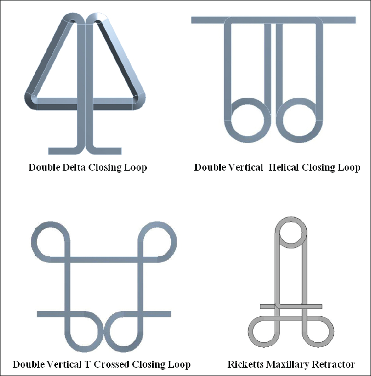
This study intended to make an assessment of four designs of retraction loop springs: Double Delta Closing Loop, Double Vertical T Crossed Closing Loop, Double Vertical Helical Closing Loop, Ricketts Maxillary Retractor made of stainless steel, and beta titanium wires of 0.017" × 0.025" and 0.019" × 0.025" dimensions in the quest of finding the best retraction loop spring for orthodontic extraction space closure.
Materials and Methods
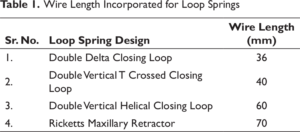
A graphic representation of each loop spring was made. The length of wire to be incorporated for each loop was obtained from standard references (Table 1). 3 To this length, 2 mm was incorporated on each side, to act as holding arms for displacement of the loop springs during their simulation. This was followed by creation of computer-assisted design (CAD) of all loop springs (Figure 1). The software utilized for CAD design fabrication was Solid Works (Dassault Systèmes, Vèlizy-Villacoublay, France).
CAD Model of all Loop Spring Designs
Wire Length Incorporated for Loop Springs
The FEM Analysis Had Three Distinct Steps
Building the model
Applying displacements and obtaining the solution
Reviewing the results
Building the FEM
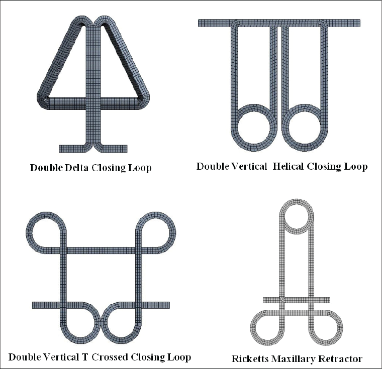
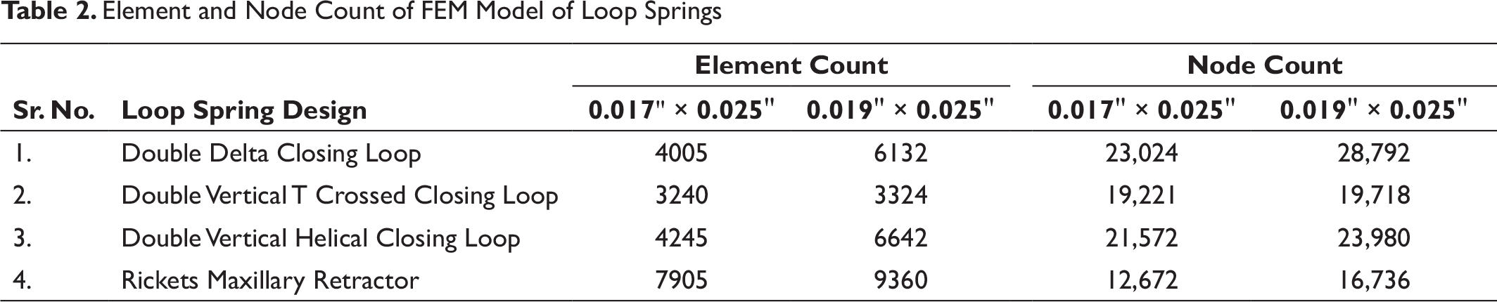
The CAD model was converted to the FEM by the software Altair Hypermesh (Altair Engineering Inc., Troy, Michigan, USA) for discretization (Figure 2). The type of the element selected for all loop springs was hex. Each loop spring was divided into a number of elements and nodes (Table 2).
FEM of all Loop Spring Designs
Element and Node Count of FEM Model of Loop Springs
Boundary Conditions
Material Property and Data Representation
The wires were assigned specific material properties that are of stainless steel and beta titanium for analyzing the results of loop activations. Young’s Modulus was taken as 160 and 62 GPa for stainless steel and beta titanium, respectively. Poisson’s ratio was 0.3 for both the materials. 4
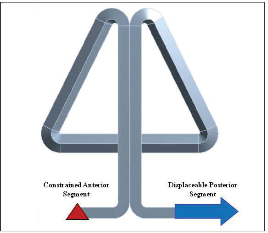
Boundary Conditions
The boundary conditions were defined so that one end (anterior segment) was restrained (it was not able to move in x-, y-, and z-axes, and it was not able to rotate around these axes). The terminal node of the posterior segment was restrained in a similar way to the anterior segment, except that it was free to move along the horizontal axis (Figure 3). This simulated the movement of the loop activation.
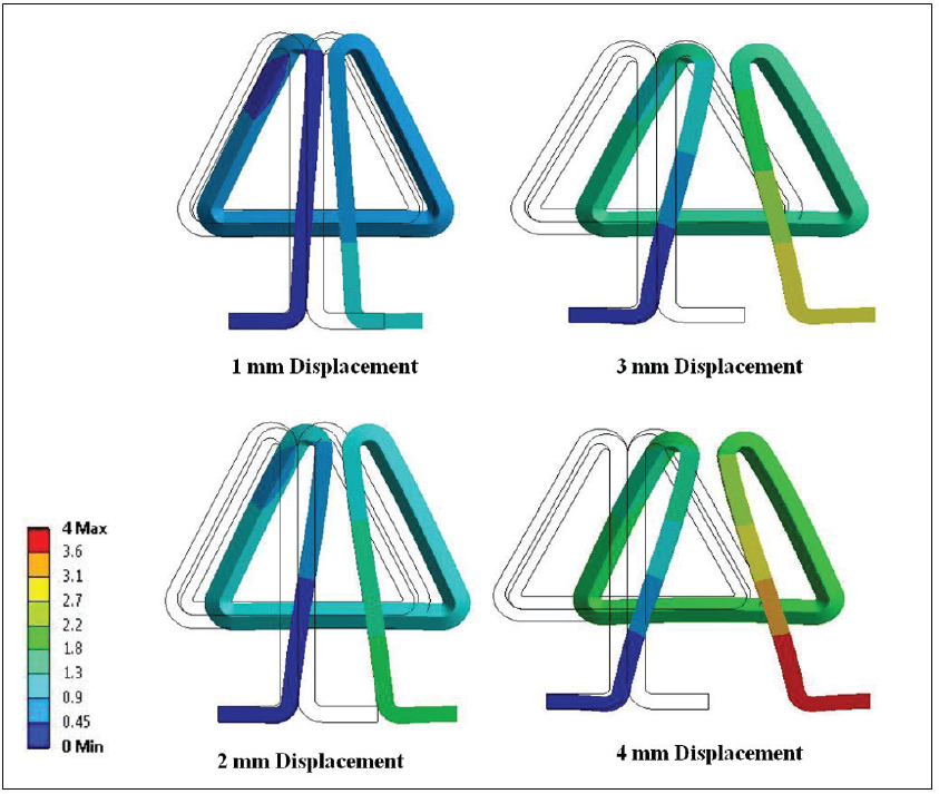
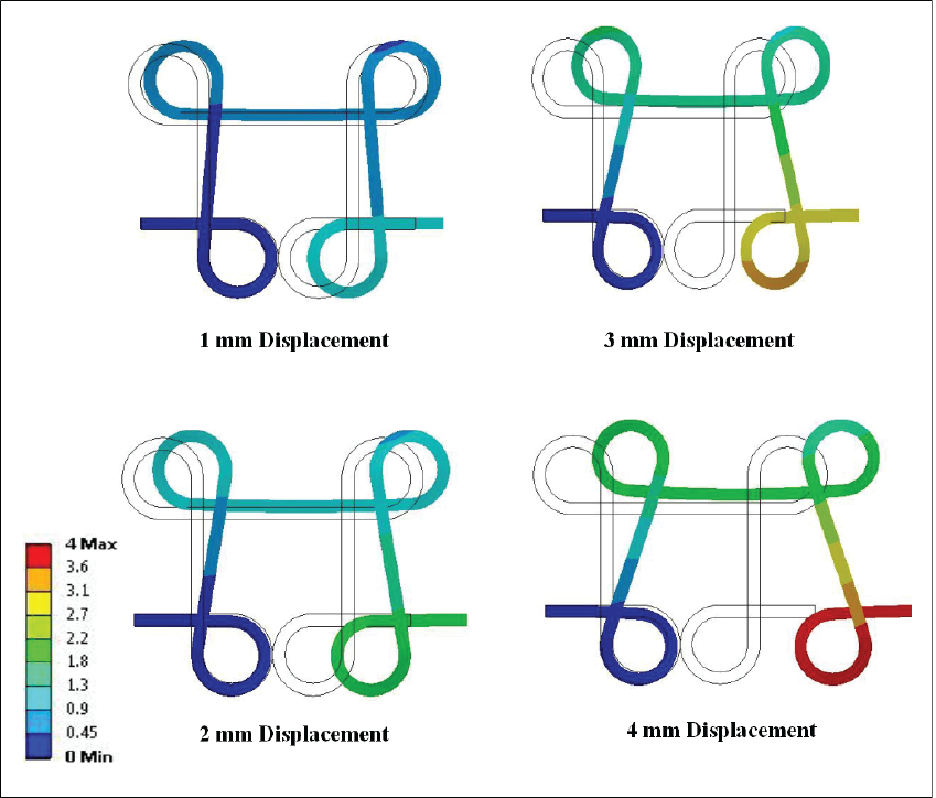
Displacement Application
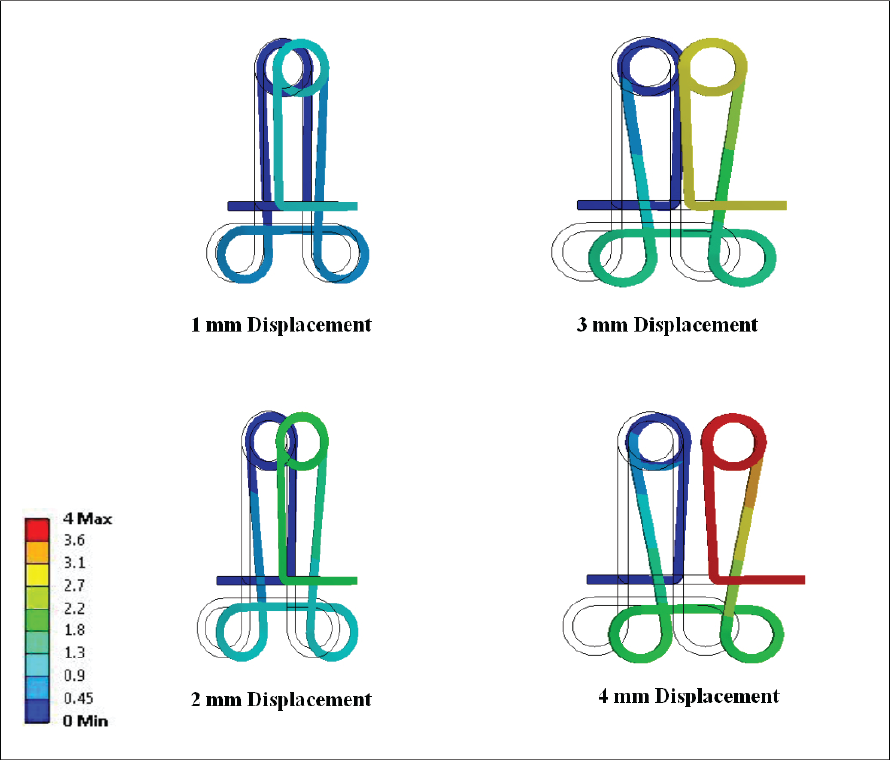
The posterior segment was activated by pulling it apart. This was done by applying displacement at an interval of 1 mm till the total displacement obtained was 4 mm (Figures 4–7). At each interval of displacement, the force generated was calculated. The calculation of this force was along the horizontal axis (the x-axis). In a normal clinical scenario, these loops springs are activated in the horizontal axis by pulling the distal end of wire and cinching it. Therefore, to simulate this action, the loops were activated along the x-axis and the force was calculated accordingly. The forces along the y (Fy)- and z (Fz)-axes were also calculated so as to obtain the resultant force (R). This resultant force divided by the displacement gave the load deflection rate value.
Displacement of Double Delta Closing Loop
Displacement of Double Vertical T Crossed Closing Loop
Displacement of Double Vertical Helical Closing Loop
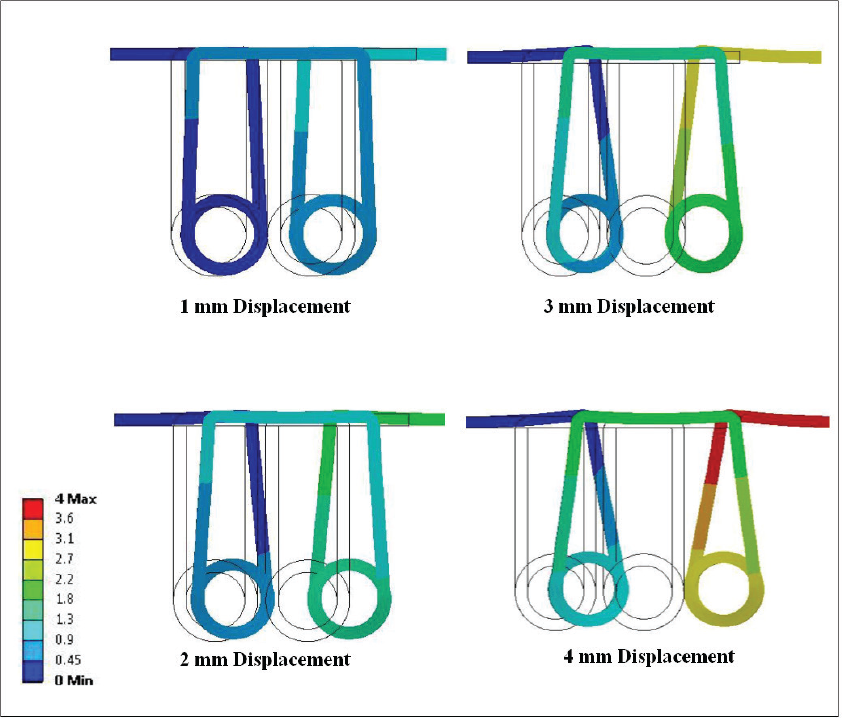
Displacement of Ricketts Maxillary Retractor
Results
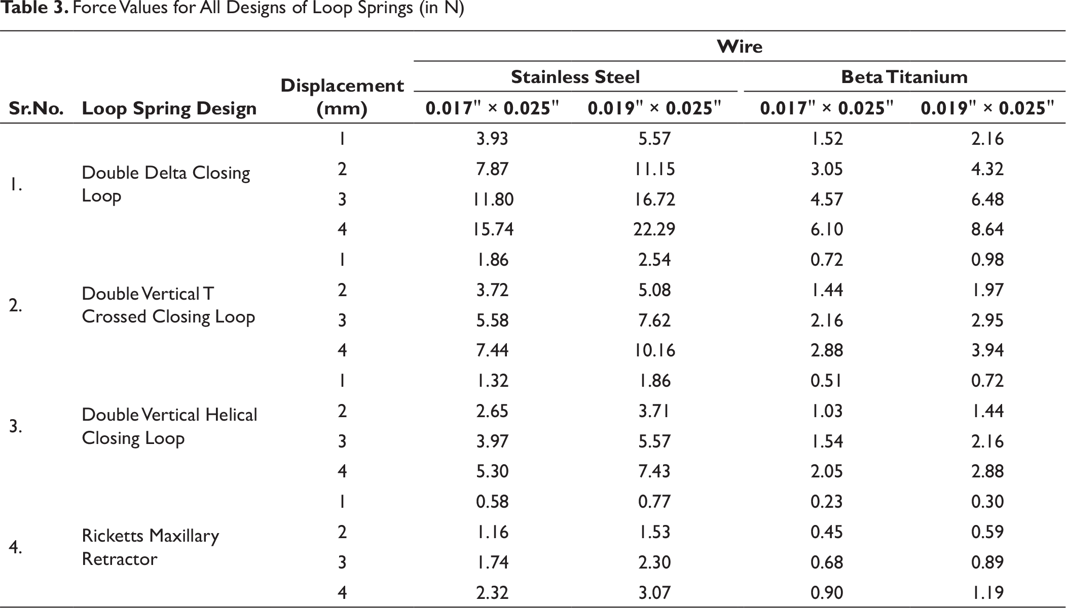
As the displacement was only along the x-axis, the forces generated along the y- and z-axes were almost equal to zero. Therefore, the resultant force value was equal to the force value along the x-axis. The results in terms of the forces (in newton, N) and load deflection rate (in newton/millimeter, N mm–1) for each of the four design of the loop springs namely Double Delta Closing Loop, Double Vertical T Crossed Closing Loop, Double Vertical Helical Closing Loop, and Ricketts Maxillary Retractor are as follows. The analysis of force and load deflection rate for the loop springs is grouped under four heads as follows.
Force Values for All Designs of Loop Springs (in N)
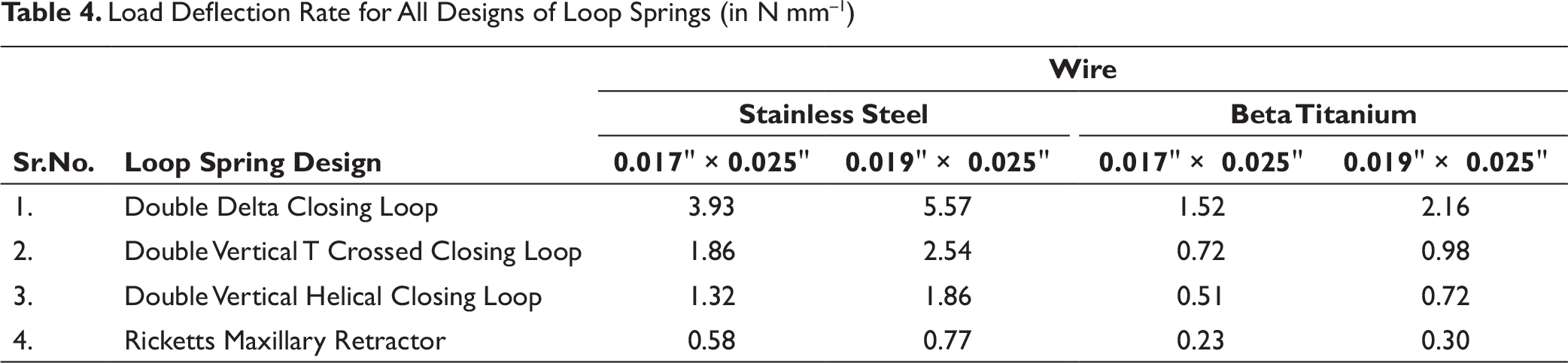
Load Deflection Rate for All Designs of Loop Springs (in N mm–1)
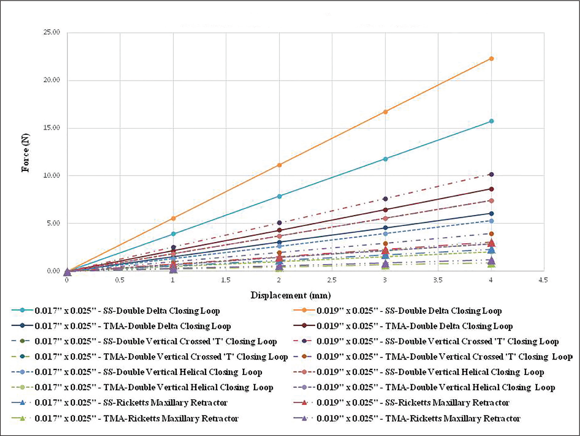
Force and Load Deflection Rate for all Loop Springs
Discussion
Burstone
5
stated that the overall stiffness of an orthodontic appliance (S) is determined by the wire stiffness (Ws) and design stiffness (As). This relation is presented by the following formula:

Design stiffness (As) is dependent on factors such as interbracket distance and the incorporation of loops and coils into the wire. Wire stiffness (Ws) can be altered by changing the cross-sectional stiffness (CS) and/or the material stiffness (MS) as designated by the following formula:

The present study determines the effects of design stiffness (spring designs), material stiffness (stainless steel and beta titanium), and cross-sectional stiffness (0.017" × 0.025″ and 0.019″ × 0.025″) on the force and load deflection rate in order to assess their efficacy and suitability for clinical use using the finite element analysis (FEA).
The magnitude of the force increased as the displacement increased from 0 to 4 mm for all the four loop spring designs of both 0.017" × 0.025" and 0.019" × 0.025" stainless steel and beta titanium (Table 3 and Graph 1). This is similar to the findings of Faulkner, Lipsett, El-Rayes, and Haberstock 2 and Rodrigues, Maruo, Guariza, Tanaka, and Camargo. 6 The force increased in a linear fashion with each millimeter of activation. This was indicative of the fact that the maximum displacement was under the elastic limit for all the loops. The load deflection rate was constant for all the 4 mm of displacements.
The loops made out of beta titanium expressed less force as compared to those of stainless steel when the design and wire dimension and displacement remained constant (Table 3 and Graph 1). Beta titanium springs delivered 0.38 times the force of stainless steel springs. This is similar to the findings of Burstone 5 who stated that beta titanium delivers 0.4 times the force of stainless steel. Menghi, Planert, and Melsen 7 also stated that loops fabricated of beta titanium delivered 40% of the force delivered by similar loops of stainless steel. The modulus of the elasticity taken in the present study was 62 GPa for beta titanium and 160 GPa for stainless steel. 4 Therefore, the force exerted by beta titanium was lesser than that of the stainless steel because modulus of elasticity determines the material stiffness, which in turn determines the relative amount of force that a wire can deliver per unit activation.
Goldberg and Burstone 8 concluded from their study that the force per unit displacement for beta titanium was 2.2 times less that of stainless steel on proper thermo mechanical preparation of beta titanium. Beta titanium is less stiff than stainless steel which has been demonstrated by numerous studies.6,9-13
The 0.019" × 0.025" wire dimensions produced more force and load deflection rate than 0.017" × 0.025" (Tables 3 and 4, Graph 1). The 0.019" × 0.025" produced approximately 1.4 times more force than 0.017" × 0.025" wire dimensions. The load deflection rate varies as the cube of the edgewise surface for the rectangular wires. 14 Similarly, in the present study when the edgewise surface of the wire was changed from 0.017" to 0.019" dimension, the load deflection rate varied as its cube. Thiesen, Shimizu, Valle, Valle-Corotti, Pereira, and Conti 13 concluded that as regards the force delivered by the loops made in stainless steel, the 0.017" × 0.025" dimension generated force levels around 26% lower than the 0.019" × 0.025" dimension. Ferriera 11 concluded with respect to the wire dimension that 0.019" × 0.025" exerted more force than the other dimensions.
Considering the design of the loop, the force value and load deflection rate from greatest to least were Double Delta Closing Loop > Double Vertical T Crossed Closing Loop > Double Vertical Helical Closing Loop > Ricketts Maxillary Retractor.
This difference between the spring designs is attributed to the length of the wire involved in designing the loop. Load deflection rate varies inversely as the cube of the length. 14 This change in length can be brought about by either increasing the vertical height of the loop or incorporation of the helices. The vertical height of a particular loop cannot be increased beyond a certain limit due to anatomical considerations. Therefore, addition of helices to the design helps to increase the wire length. With regards to the description of the helices, one complete turn was considered as one helix and a half turn is considered as half helix. On comparison in terms of incorporation of helices, Double Delta Closing Loop has none, Double Vertical T Crossed has 4, Double Vertical Helical Closing Loop has 3, and Ricketts Maxillary retractor has 5. Therefore, the Ricketts Maxillary Retractor has the least load deflection rate and force value. But the Double Vertical T Crossed Closing Loop has 4 helices still the load deflection is more than that Double Vertical Helical which is due to the fact that the length of the wire incorporated for the Double Vertical Helical Closing Loop is greater than it.
Thiesen, Shimizu, Valle, Valle-Corotti, Pereira, and Conti 13 tested stainless steel teardrop-shaped loops with helix, measuring 8 mm in height and 4 mm in width, for 1, 2, and 3 mm activations. On quantifying the load deflection rate of teardrop-shaped loops with and without helix, lower magnitude values and higher constancy for the loops with helices was found. Rodrigues, Maruo, Guariza, Tanaka, and Camargo 6 concluded that the teardrop-shaped loops with helix produced lighter forces and had low load deflection rate as compared to the one without helix.
Chen, Markham, and Katona 15 concluded that increasing the vertical or horizontal dimensions of a T loop reduces the load-deflection rate. Faulkner, Lipsett, El-Rayes, and Haberstock 2 stated that the addition of the apical helix allows the activation to be increased approximately 60% (from 1.0 to 1.6 mm) before the spring can be expected to be permanently deformed because of yielding of the material.
The Ricketts Maxillary Retractor in beta titanium had a spring rate of 23.45 gm mm–1 for 0.017" × 0.025" and 30.59 gm mm–1 for 0.019" × 0.025" which are both lower than the value found by Burstone 16 (33 gm mm–1) for the composite T-loop, the centered T-loops (0.017" × 0.025", TMA) studied by Burstone, Steenbergen, and Hanley 17 (approximately 55 gm mm–1), and the canine-retraction developed by Gjessing 18 (45 gm mm–1). This is indicative of its better efficiency as retraction loop.
Bench, Gugino, and Hilgers 3 verifying cobalt-chromium 0.016" × 0.016" (RMO) springs on a Double Vertical Helical Closing Loop design, 60 mm long, found that the spring rate was 75 gm mm–1. The load deflection rate obtained in this study for the same design of the similar length is 134.60 gm mm–1 for 0.017" × 0.025" stainless steel, 189.66 gm mm–1 for 0.019" × 0.025" stainless steel, 52 gm mm–1 for 0.017" × 0.025" beta titanium, and 73.14 gm mm–1 for 0.019" × 0.025" beta titanium. The higher values obtained in stainless steel material could be attributed to difference in the material properties as well as the higher wire dimensions used in the present study. The lower values of beta titanium are due to the fact that Cobalt-Chromium delivers twice the amount of force as beta titanium. 19
Ferreira 11 found that the stainless steel 0.019" × 0.025" (3M Unitek), 0.019" × 0.025" (Morest), Titanium-molybdenum 0.017" × 0.025" (Ormco), and 0.019" × 0.025" (Ormco) Double Delta had a spring rate of 275.9 gm mm–1, 257.5 gm mm–1, 84.9 gm mm–1, and 138.3 gm mm–1, respectively. The Double Delta design of 0.019" × 0.025" stainless steel, 0.017" × 0.025" beta titanium, and 0.019" × 0.025" beta titanium in our study gave a spring rate of 567.98 gm mm–1, 154 gm mm–1, and 220.25 gm mm–1. Comparing the outcome of Ferreira with our study, the higher values in our study could be attributed to the difference in the length of the wire incorporated. The design of Ferreira incorporates around 68 mm (32 mm for the design proper and 36 mm for the arms which go for attachment on the linear displacement transducer), and our study incorporates 40 mm (36 mm for the design and 4 mm for the holding arms).
A low load deflection value is important in a loop since it allows the orthodontist to apply light, continuous, and controlled forces. It is desirable to have the lowest load-deflection rate possible because with a low load-deflection rate a large activation is required in order to build up the needed force level. The forces would be released over longer duration. This facilitates fewer reactivation appointments.
FEM has gained popularity as a new research tool in the field of dentistry and orthodontics in particular. It has helped in simulating and evaluating conditions which are difficult to carry out in a clinical scenario. In the field of orthodontics, its application has been primarily for structural stress analysis. This includes studies on wire configurations, determination of center of resistance and center of rotation of teeth, stresses in anatomical structures such as TMJ, periodontal ligament, jaws, and cranium as well as stresses in brackets, wires, adhesives, etc. It is used for analysis of skeleton, tissue growth, remodeling, degeneration, and improving designs of appliances. FEM has been used to study stress strain levels induced in internal structures. 20 It’s application include assessment of complex shape changes and orthodontic tooth movement. 21 It is also used as a tool for morphometric analysis in caraniofacial biology. 22 The mechanical behavior of orthodontic wires and different design of brackets and their contact relationship can be well modelled and simulated by the FEM. Thus, FEM has been an important tool in the development and improvement of orthodontic bracket and wires design. 23
FEM has a few limitations as well. One of the challenges with FEM is modelling of the structure to be exact to its actual configuration. Morphological traits of complex anatomical structures are difficult to be depicted with reliability. This is due to the practical limitation posed in assigning or choosing the correct number and type of elements to define a structure. Likewise, some assumptions may need to be made while allocating boundary conditions and representations of loading conditions. Also, FEA is based on the model which is created for a specific research. This may not account for all the possible naturally occurring variations. FEM cannot accurately simulate the biological dynamics of craniofacial structures. Variations in the material properties assigned may change the results.
Hence, finite element research has to be refined and validated through more clinical experimentation.
Conclusion
It is clear that the magnitude of forces and load deflection rate generated by activation of loops depend on many confounding factors such as wire material, wire dimensions, and loop configurations.
All the four retraction loops, those of both stainless steel and beta titanium material and 0.017" × 0.025" and 0.019" × 0.025" wire dimensions demonstrated increased force values as the displacement increased by unit mm. With wire material and wire dimensions remaining the same, Ricketts Maxillary Retractor showed the lowest force levels and load deflection rate. This was followed, in ascending order, by Double Vertical Helical Closing Loop, Double Vertical T Crossed Closing Loop, and Double Delta Closing Loop. With design and wire dimensions of the loop springs remaining the same, those made from beta titanium demonstrated lower force levels and load deflection rate than those of stainless steel. Regardless of the design and constituent wire material of the loop springs, those of wire dimension 0.017" × 0.025" demonstrated lower force levels and load deflection rate than those of 0.019" × 0.025". With constituent wire material of the loop springs remaining the same, same force levels were generated by 0.017" × 0.025" Double Vertical T Crossed Closing Loop and 0.019" × 0.025" Double Vertical Helical Closing Loop.
Declaration of Conflicting Interests
The authors declared no potential conflicts of interest with respect to the research, authorship, and/or publication of this article.
Funding
The authors received no financial support for the research, authorship, and/or publication of this article.