
Abstract
Abstract
Objective: The aim of this study was to develop a method to simulate root position in the patient and to evaluate the accuracy of all procedures.
Materials and Methods: In Part I, the accuracy of a tooth model generated using cone-beam computed tomography (CBCT) was evaluated. Mesiodistal width was measured and compared between digital models and actual teeth. In Part II, the accuracy of simulated root positions generated in the scanned model was evaluated. Simulated root models were superimposed on the scanned dental model using the best fit method. The distances between the reference wire and the tooth were compared. In Part III, the simulated method was used with real orthodontic patients. The distances between the mini-implant and the tooth were compared.
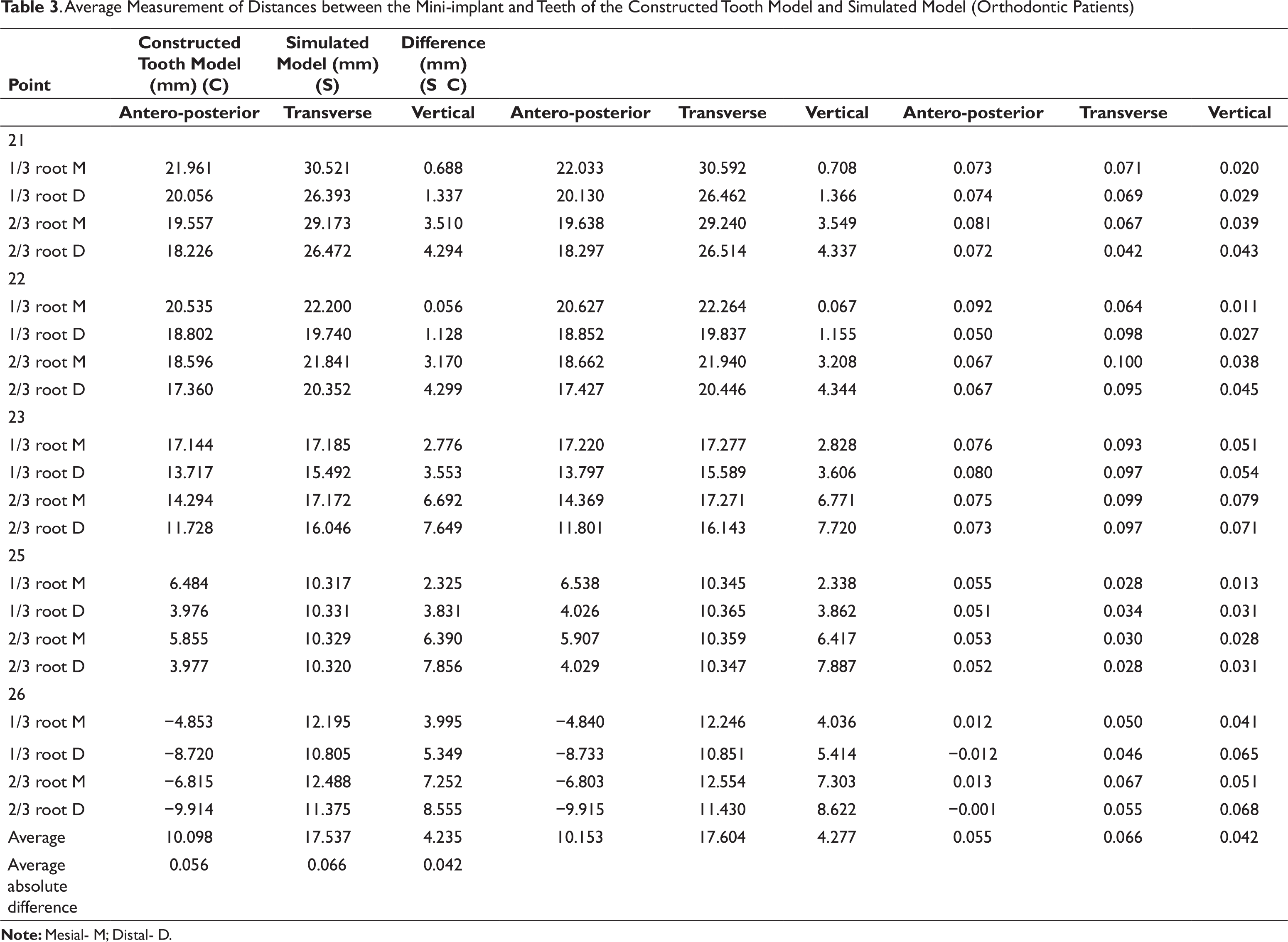
Results: Part I: The range of the differences was −0.106 to 0.152 mm. Part II: The range of the differences between the distance of the constructed tooth model and the simulated model was −0.065 to 0.256 mm. Part III: The range of the differences between the distance of the constructed tooth model and the simulated model was −0.089 to 0.135 mm. This technique provided high accuracy, with an average error of only 0.054 mm.
Conclusion: High accuracy of the constructed model was achieved. Simulation of root position in a patient can be accomplished by combining data from CBCT and the digital model. This technique might be used effectively in orthodontic treatment.
Introduction
An important issue in orthodontic treatment is occlusion of the teeth that will provide good function, esthetics, and stability. In the 1970s, Andrews introduced 6 keys to normal occlusion, including crown angulation and inclination.1,2 However, angulation and inclination generally depend on the long axis of the tooth, consisting of the crown and root.3,4 Clinically, angulation may be evaluated by the crown only, but in some cases, the crown is abraded from function or pathology and is not suitable for use in clinical evaluation. 4 To obtain normal occlusion in orthodontic treatment, good position of the root is necessary. In addition, improper root position will increase the risk of alveolar bone dehiscence and gingival recession. 5
An orthopantomogram (OPG) is usually used in orthodontic treatment for screening the oral structure. In practice, some clinicians use an OPG to evaluate the parallelism of the roots. 6 A previous study reported that OPGs were subject to image distortion, and so, the clinical assessment of tooth angulation should be approached with extreme caution. 7 Cone-beam computed tomography (CBCT) has been considered the examination of choice in dental treatment when 3-dimensional (3D) information is needed and also in the evaluation of the root position in orthodontic treatment. 8 Although the radiation dose from CBCT is 35% less than from conventional computed tomography (CT), 9 and many orthodontists routinely use CBCT for all patients, patients may be exposed to excessively high levels of radiation during serial CBCT. Therefore, to evaluate root position with CBCT, the “as low as reasonably achievable” principle should be followed, 10 and a methodology without serial CBCT in the evaluation should be created.
Clinically, the crown of the tooth can be used to predict the root position, with consequent confirmation through radiographs. However, this method has been found to have some errors. Re-evaluation with the radiograph method is therefore performed in only a few cases. Root position evaluation techniques have been newly developed to reduce the radiation dose to patients. Apical root resorption can occur in orthodontic patients, but several studies have reported that the average amount of resorption is slight and mostly occurs only at the apical root.11-14 The long axis and majority of the root are not affected by apical root resorption. Therefore, CBCT data taken at the initial time of treatment can be used for estimating root position throughout orthodontic treatment by using a computer-aided technique. Root position evaluation is necessary to avoid the proximity of the root to the adjacent teeth or alveolar bone cortex, which is one of the risk factors for root resorption in orthodontics.15-17 In addition, root position evaluation is necessary in the case of orthognathic surgery, implant placement, and endodontic surgery, when root position could possibly affect the treatment plan or treatment procedure.
Recent studies have introduced a new methodology to track root position at any stage of treatment with a single CBCT image and multiple intraoral scans.18,19 However, this approach was presented in an ex vivo typodont and in patients with complete treatment only. In reality, orthodontic patients have brackets bonded on the teeth surfaces, which may affect the accuracy of the dental model due to difficulties in taking impressions and the presence of artifacts in the CBCT image. The aim of this study was to develop a methodology to evaluate the root position in patients during orthodontic treatment. In addition, the accuracy of all procedures of this new technique was evaluated.
Materials and Methods
The study was divided into 3 parts. Part I evaluated the accuracy of a computer-constructed tooth model generated from CBCT. Part II evaluated the accuracy of the simulated root position generated from the scanned dental model. Part III applied the simulated root position method in orthodontic patients. The research protocol was approved by the Research Ethics Committee of the Faculty of Dentistry, Prince of Songkla University (Project No. EC580410PLR).
Part I
Five extracted upper maxillary human teeth were collected from the Department of Oral Surgery, Dental Hospital, Faculty of Dentistry, Prince of Songkla University. All teeth, including lateral incisor, canine, first premolar, second premolar, and first molar, were cleaned. Six points used as landmarks were drilled on the surfaces using 0.5-mm-diameter round burs. The points of measurement were marked on mesial and distal sides at 3 levels: the height of the contour of crown, one-third of the root length, and two-thirds of the root length (Figure 1). Mesiodistal width of each tooth at all 3 levels was measured 2 times using a digital Vernier caliper with an accuracy of ±0.02 mm (Mitutoyo, Kawasaki, Japan). Each measurement was performed at 2-week intervals.
A custom dental model simulating an orthodontic patient’s dental structure was made by using all 5 extracted teeth embedded into a plaster dental model. To prepare the custom dental model, an impression of each of the extracted teeth was taken using alginate and pouring dental plaster to duplicate the crowns of all teeth. One dental model of a patient with normal occlusion was ground with a carbide bur at the area of the lateral incisor, canine, first premolar, second premolar, and first molar. The crowns of ground teeth were then substituted with duplicate crowns of extracted teeth. Pink wax was used to replace the gingival area. An alginate impression was made on this transformed dental model. All 5 extracted teeth were aligned, and then orthodontic dental stone was poured into the impression. Roth’s prescription preadjusted edgewise brackets (Ormco, Glendora, CA, USA) with 0.018 × 0.025-inch slots were attached on the incisor, and brackets with 0.022 × 0.028-inch slots were attached on the canine and posterior teeth to simulate an orthodontic patient’s dental structure, following the protocol of our orthodontic clinic. A stainless steel wire, 0.016 × 0.016 inches and 6 mm in length, was bent into a right angle and attached on the buccal side of the plaster model between the cementoenamel junction of the second premolar and the first molar to use as a reference point. This model was called the “custom dental model,” as shown in Figure 1.
Experimental models used in the study. Left: extracted tooth drilled at the level of the height of the contour of the crown, one-third of the root length, and two-thirds of the root length; Center: custom dental model consisting of 5 teeth with bonded brackets and reference wire; Right: custom dental model image captured with low-dose dental computed tomography
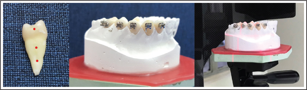
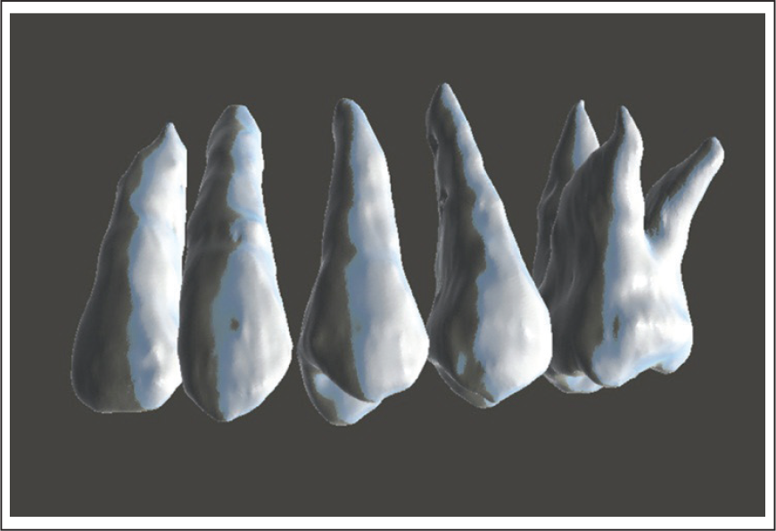
For construction of the 3D model, the custom dental model image was captured with low-dose dental CT (Veraviewepocs; J. Morita, Tokyo, Japan). The dental CBCT scan data were saved in DICOM format and later converted to a “constructed tooth model.” The model consisted of a lateral incisor, canine, first premolar, second premolar, and first molar and was constructed using 3D image processing and editing software (ITKSNAP open-source software; www.itksnap. org) (Figure 2f). Mesiodistal widths at the level of the height of the contour of the crown, one-third of the root length, and two-thirds of the root length of each constructed tooth model were measured. The widths were measured again at 2-week intervals; on each occasion, measurements were performed 2 times and average data were calculated. Mesiodistal widths at all 3 levels of the constructed teeth were compared with those of the extracted teeth.
Part II
A dental CBCT scan from Part I was used to construct the reference wire and then combined with the constructed tooth model from Part I. The constructed tooth model was reoriented, the occlusal plane was parallel to the horizontal plane, the midsagittal plane was parallel to the vertical plane, and the right angle of the reference wire was set as the center. The distances between the right angle of the reference wire and points at the level of the height of the contour of the crown and one-third and two-thirds of the root length on both mesial and distal sides were measured into anteroposterior, transverse, and vertical distance.
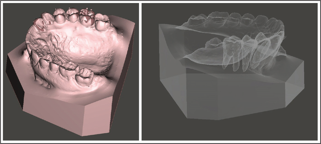
The custom dental model from Part I was scanned using a calibrated digital model scanner (R700 Orthodontic 3D Scanner; 3Shape, Copenhagen, Denmark). A simulated root model was produced from individual tooth models from Part I superimposed over the scanned dental model based on the best-fit method at the area of palatal side using 3D image processing software (Geomagic Wrap software; www.geomagic.com) (Figure 3). The simulated root model was reoriented following the constructed tooth model. The distances between the right angle of the reference wire on the scanned digital dental model and points at the level of the height of the contour of the crown and one-third and two-thirds of the root length on both mesial and distal sides of each root on the simulated model were measured into anteroposterior, transverse, and vertical distance. Distances between the reference wire and measurement points on the teeth on the constructed tooth model and the simulated root model were compared.
Tooth models constructed using cone-beam computed tomography of the custom dental model
Part III
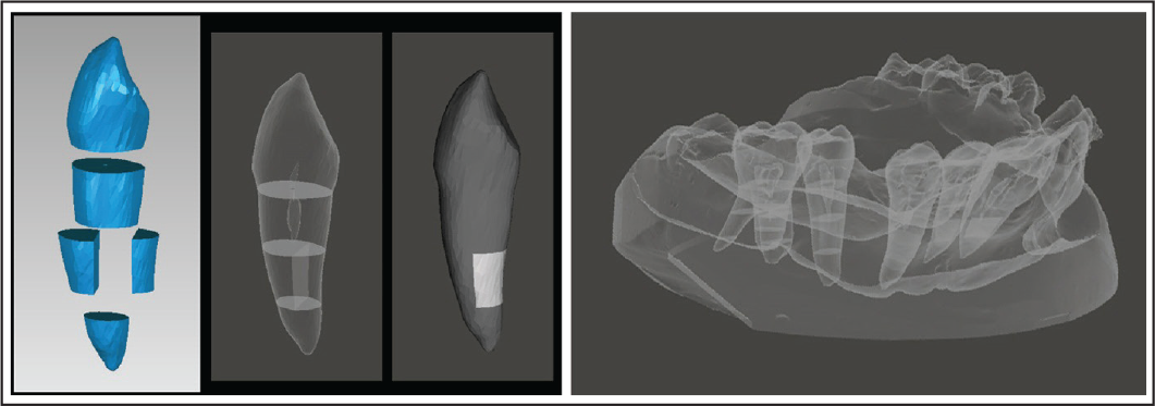
Four orthodontic patients who had already obtained both CBCT images and dental model were selected from Orthodontic clinic, Faculty of Dentistry, Prince of Songkla University. CBCT data during orthodontic treatment of each patient in DICOM format were converted to a constructed tooth model, which consisted of a central incisor, lateral incisor, canine, second premolar, first molar, and mini-implant between the second premolar and first molar. Each tooth model was sectioned into buccal and palatal sides, and the root was divided at one-third and two-thirds of the root length, marked as reference points (Figure 4, left). The constructed tooth model was reorientation. Distances between the mini-implant and points at the level of the height of the contour of the crown and one-third and two-thirds of the root length on both mesial and distal sides were measured into anteroposterior, transverse, and vertical distance.
The plaster dental model from the patients was taken on the same day as CBCT scanning, using a calibrated digital model scanner. A simulated root model was generated using each constructed tooth model superimposed on the scanned dental model by means of the best-fit method at the area of the palatal side of individual teeth (Figure 4, right). The simulated root model was reorientation. Distances between the mini-implant and points at one-third and two-thirds of the root length on both mesial and distal sides of each tooth in the simulated root model were measured into anteroposterior, transverse, and vertical distance. Measurements were performed as in Part II. Distances between the mini-implant and measured points on the constructed tooth model and the simulated root model were compared. All measurement procedures were performed 2 times by only 1 researcher to reduce errors, and measurements were done at 2-week intervals. The method error was calculated through duplicate measurements by using Dahlberg’s formula. Mesiodistal widths of the teeth and distances between the reference wire in the custom dental model or mini-implant in the measured points on the teeth were analyzed using descriptive statistics.
The simulated model from the custom dental model. Left: superimposition of the constructed tooth model and the scanned model using the palatal side of individual teeth; Right: simulated model displaying root position generated by combining the constructed tooth model with the scanned model
The simulated model from patient data. Left: reference points were marked on the constructed tooth model at the level of the height of the contour of the crown and one-third and twothirds of the root length; Right: the simulated model of the patient with root position based on the combined constructed tooth model and the scanned model
Results
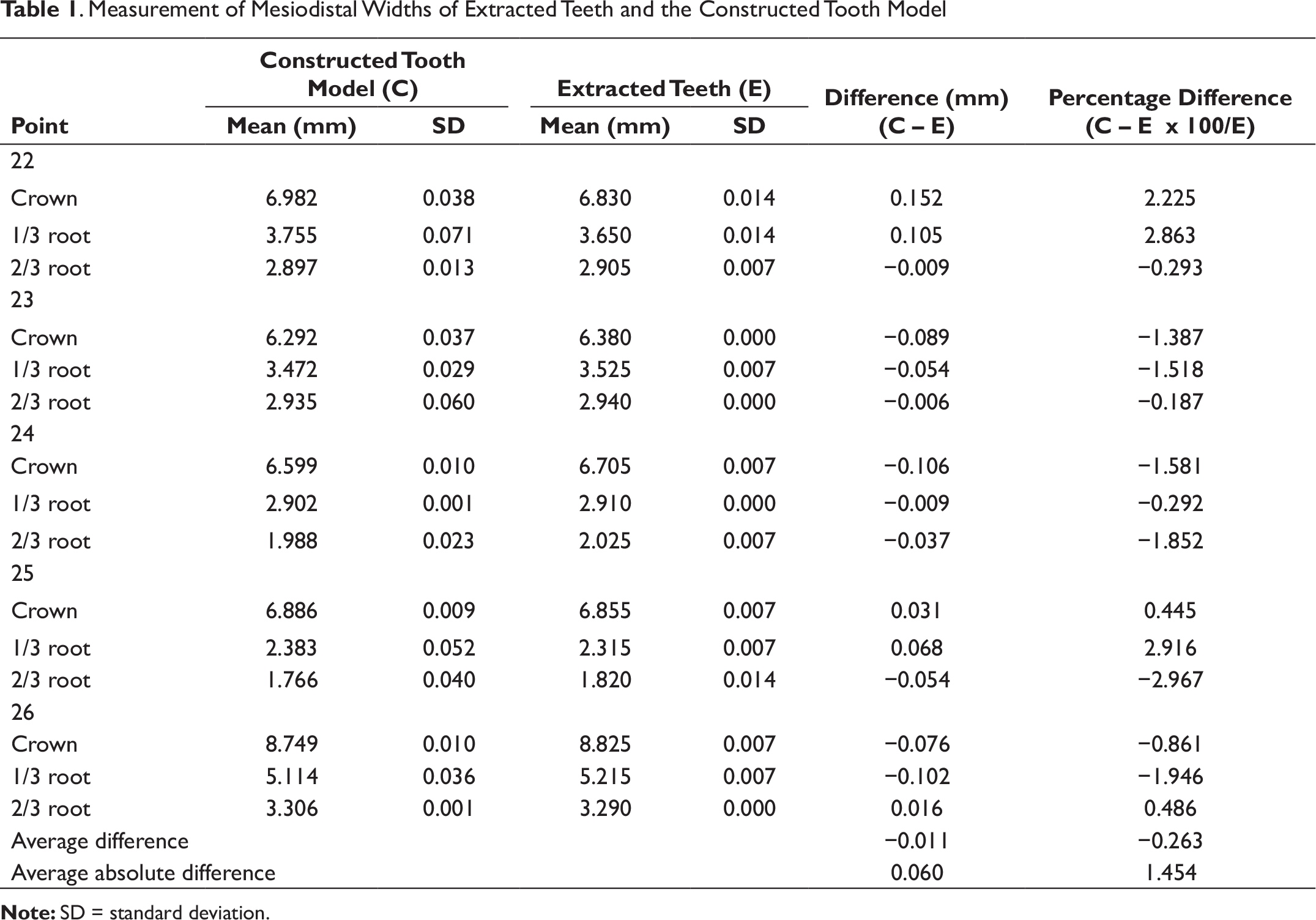
The results of Part I are shown in Table 1. Mesiodistal widths at the level of the height of the contour of the crown and one-third and two-thirds of the root length of each tooth were averaged from 2 measurements. To compare tooth sizes, the extracted teeth were measured using an electronic Vernier caliper and compared with the teeth of the constructed tooth model. The range of the differences was −0.106 to 0.152 mm or −2.967% to 2.916%. The errors of size measurement using an electronic Vernier caliper of the CBCT-constructed 3D model were 0.008 and 0.035 mm, respectively.
Measurement of Mesiodistal Widths of Extracted Teeth and the Constructed Tooth Model
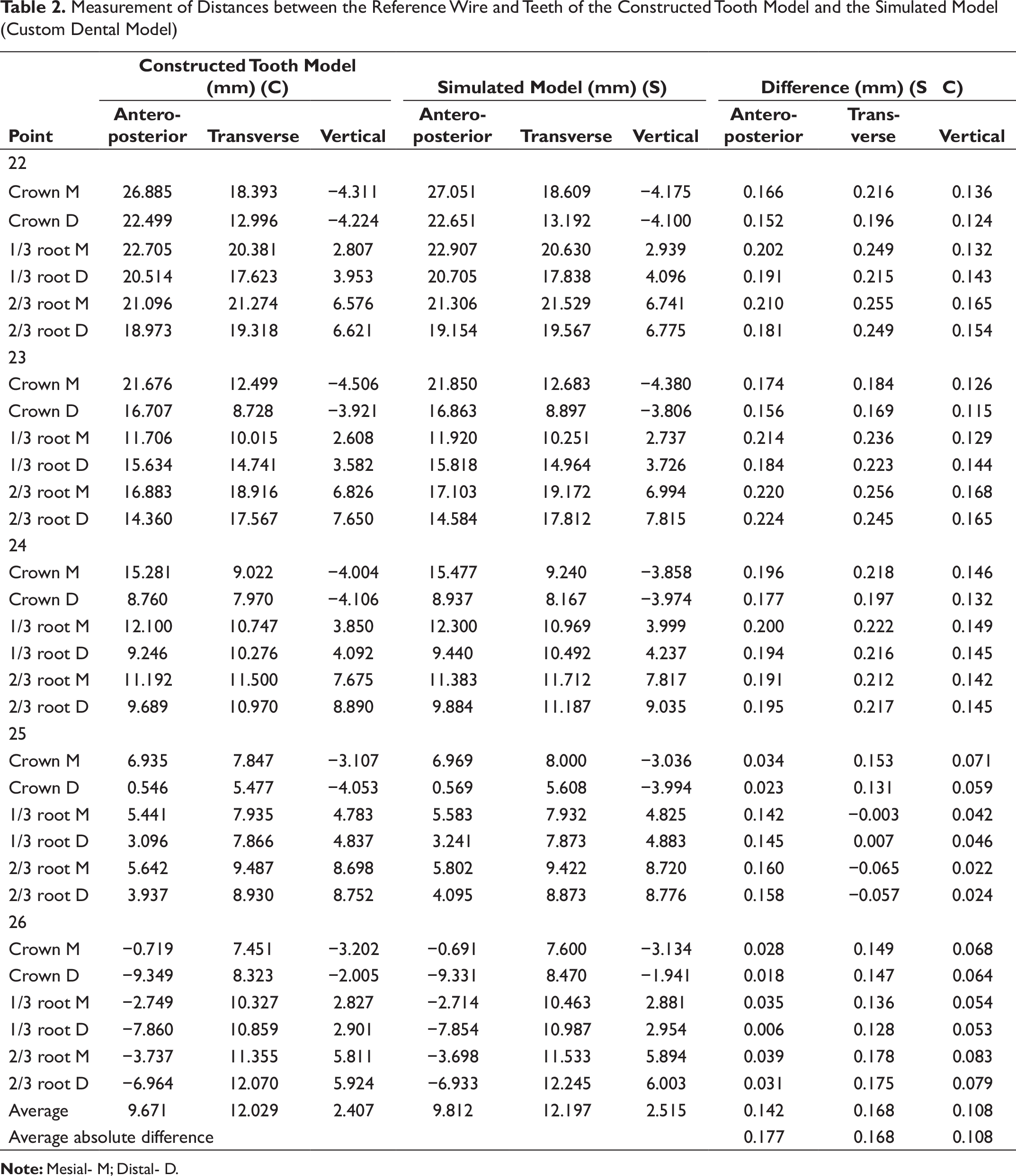
Measurement of Distances between the Reference Wire and Teeth of the Constructed Tooth Model and the Simulated Model (Custom Dental Model)
Discussion
The study was divided into 3 parts to identify any errors that may occur during the process of root simulation. In the first part, errors from CBCT and the 3D construction process were investigated by comparing with the actual tooth size. The second part evaluated errors in the root simulation process. The third part evaluated errors when all processes were applied in orthodontic patients to test the methodology in a real situation.
In this study, the extracted teeth were used as measurable objects to evaluate the accuracy of the computer-constructed model generated by using CBCT. CBCT of extracted teeth was able to generate 3D models, but it could not simulate an orthodontic patient, which can affect the quality of 3D modeling because bonded brackets can cause artifacts in the radiograph and distort the areas of teeth adjacent to the brackets. Therefore, to replicate a real-life situation in this study, the teeth were bonded with brackets before the CBCT radiograph was taken.
The geometry of the constructed model possibly affects the root position in the present technique. Mesiodistal width of the extracted teeth was therefore selected to measure for comparison with measurements obtained from the constructed tooth model. The result revealed that the average absolute difference was only 0.060 mm (Table 1), which would appear to be insignificant. Inaccuracies of mesiodistal width measurement in constructed CBCT 3D teeth could occur from the voxel size of the CBCT image, the construction process, and measurement errors. Voxel size can affect the quality of the CBCT image when 1 voxel represents more than 2 types of tissues, such as the junction areas between periodontal ligaments and teeth. The average density of different tissues was usually assigned to a voxel. 20 A previous study indicated that there was no significant difference in volume reconstruction when the voxel size was under 0.20 mm. 21 The voxel size used in this study was 0.13 mm, and therefore, the difference was very minor. Dahlberg’s formula was used as a method of quantifying validation of errors between each measurement in this study. Dahlberg’s error for the measurement using a digital Vernier caliper was only 0.008. This meant that the direct method of measurement was very accurate and repeatable. The error of size measurement in the constructed 3D CBCT model was 0.035 mm, which was very small as well. It seems that the constructed model in this study was similar to the prototype and could provide high accuracy for use in orthodontic evaluation.
The results of Part II showed that the average error of the simulated root position technique in this study was 0.139 mm—slightly less than that of a previous study, which was 0.167 mm. This might be due to the use of an indirect superimposition technique before comparing each measurement. 18 The errors might increase when multiple processes are performed. However, in the present study, the reference wire was attached on the custom dental model, and the wire appeared both in the CBCT image and scanned model. Correspondingly, the mini-implant was used in the patients as the reference point. Therefore, this superimposition technique could be achieved in 1 step to decrease errors in all processes. In addition, the palatal area was used for superimposition because it is difficult to obtain an intact impression from an orthodontic patient with bonded brackets or another appliance, which usually cause the impression materials to tear or distort.
Another factor that could affect the accuracy of the present technique was the accuracy of the CBCT image and scanned digital model. The 0.2 to 0.3 mm voxel size of CBCT images was used in a previous study, 22 and it was found that linear measurements of the dry skull and the CBCT image were identical and highly correlated. The better voxel size of CBCT images in this study might be responsible for more accurate data compared with previous studies.23-25 It has been evidenced that digital models are accurate and reproducible for linear measurement. Previous studies have reported that errors of the 3D scanner ranged from 0.072 to 0.300 mm.26-28 In this study, the accuracy of the scanned digital model was found to be 0.020 mm, which had higher accuracy that those of previous results.
Average Measurement of Distances between the Mini-implant and Teeth of the Constructed Tooth Model and Simulated Model (Orthodontic Patients)
The present research study was mainly related to the evaluation of the accuracy of a 3D constructed model using CBCT and root simulation process using CBCT and digital dental model, which is important for the analytical process in many procedures. A limitation of this study was that the results did not deliver any relation to the clinical application in orthodontic procedures. However, this part of the study has validated that this technique provided high accuracy for further application. The authors have applied this technique combined with finite-element method to simulate treatment outcome in orthodontic tooth movement and compared with real clinical tooth movement. This benefit of digital orthodontic procedure would provide expediency both for orthodontists and patients.
Conclusions
Based on the results of this study, it can be concluded that
Errors of the 3D constructed model derived from good-quality CBCT data were small; this technique might be used effectively for orthodontic treatment. Simulation of the root position of patients during orthodontic treatment can be achieved by combining data from CBCT and a digital model. This technique provides high accuracy, with an average error of only 0.054 mm.
Acknowledgments
This study was supported by the Faculty of Graduate Studies, Prince of Songkla University, Hat Yai, Songkhla, Thailand and the Common Oral Diseases and Epidemiology Research Center (PhD program).
Funding
The authors received no financial support for the research, authorship, and/or publication of this article.
Declaration of Conflicting Interests
The authors declared no potential conflicts of interest with respect to the research, authorship, and/or publication of this article.