
Abstract
Objectives
Nasogastric tube use can lead to pressure injury. Some nasogastric tube securement devices (NG-SD) include hard plastic components. In the current study, we assessed the differences in strain profiles for two NG-SD, one with hard segments and one without hard segments, using finite element analysis (FEA) to measure strain and deformation occurring at the nasogastric tube–tissue interface.
Methods
FEA in silico models of devices were based on device mechanical test data and clinically relevant placements. Peak strain values were determined by modelling different scenarios using Abaqus software whereby the tubing is moved during wear.
Results
The modelling showed peak strains ranging from 52% to 434% for the two NG-SD depending on the tubing placement and device type. Peak strain was always higher for the hard plastic device. Tissue strain energy was a minimum of 133.8 mJ for the NG-SD with no hard parts and a maximum of 311.6 mJ for the NG-SD with hard parts.
Conclusions
This study provided evidence through in silico modelling that NG-SD without hard components may impart less strain and stress to tissues which may provide an option for tube securement that is less likely to cause medical device-related pressure injury.
Keywords
Introduction
Pressure injuries and medical device-related pressure injuries (MDRPI) have a complex aetiology and often result in unnecessary morbidity for patients requiring devices to be placed so as to deliver therapy. 1 Nasogastric (NG) tubes and endotracheal tubes are the two most common devices used in the intensive care setting and which contribute to most MDRPIs throughout the patient’s clinical course. 2 NG tube-associated pressure ulcers (NGaPU) are reported to comprise 8% of all MDRPI yet are frequently neglected and chronically understudied, despite incidence rates ranging from 10% to 29%.3,4
It is believed that prolonged contact between tissues and hard objects, resulting in excessive tissue strain, can lead to ischemic necrosis and pressure injury. 5 MDRPIs have been recognised as an important clinical problem. 6 The nasal mucosa are susceptible to pressure injury and NG tube use can lead to injury. 7 In a study evaluating patients in the intensive care unit (ICU) with an NG tube placed for 48 hours or more, the columella was the site most often associated with mucosal injury, followed by the anterior septum. 1 Some NG tube securement (NGTS) devices on the market are bulky and include hard plastic components. Recently, a new device without hard components became available which is believed to reduce the risk of pressure injury. A schematic of this device is shown in Figure 1.

Schematic representation of device without hard components. The device is composed of a flexible and transparent laminate. Colour has been added to this image for illustrative purposes.
Whereas pressure from a tube or device and the resulting tissue strain are key factors, establishing a single causative tissue strain value for MDRPIs proves challenging owing to compounding factors like friction, moisture, and underlying health conditions. Research suggests that high-risk patients may develop pressure injuries within a few hours of unrelieved pressure.8,9 An in vitro, myofibroblast-based muscle model indicated that the cells were able to withstand continuous engineering strains of up to 65% for 1 hour and engineering strains of 40% for up to 4.75 hours. 10 Other studies have shown in cellular compression models that cells may become irreversibly damaged when exposed to approximately 72% strain for approximately 30 s in vitro. 11 These cellular models lack the hierarchical structure of tissue, but both lines of evidence emphasise the importance of preventative strategies and NGTS devices that minimise tissue strain and time exposed to the strain.
Currently, no in vivo methods exist with which physical measurements of the stresses and strains imparted to tissue and mucus membranes during NG usage can be made. Instead, finite element analysis (FEA) modelling is used as an alternative. FEA uses mathematical equations and computational modelling to assign numerical values to stresses and strains on skin tissue while deforming in response to loading. We assessed the differences in strain profiles for two NGTS devices with and without hard segments using FEA to measure strain and deformation occurring at the NG tube–tissue interface.
Methods
Model conditions and device placement
An anonymised male human head computed tomography (CT) scan was obtained (Archibald Doe LO 77654033_19950903 CT, head/brain without contrast from https://pydicom.github.io; open-source image) and imported into 3D segmentation software (Simpleware ScanIP S-2021.06, Synopsys Inc., Mountain View, CA, USA). A portion of the face, including the anterior portion of the nasal cavity, was segmented. The face was imported into SolidWorks (SOLIDWORKS Premium 2018 SP5.0, Dassault Systems, Johnson, RI, USA) as a graphic object and manually traced in 3D as lofted body. The face object was then imported into Abaqus (Abaqus/CAE 2020, Dassault Systems) for meshing with 25918 tetrahedral C3D10M quadratic elements.
Similarly, two NGTS assemblies, one with no hard components (NGTS-S; 3M™ Nasogastric Securement Device, Solventum, St. Paul, MN, USA) and one with a plastic tube connector (NGTS-H; Hollister Feeding Tube Attachment Device, Hollister Inc., Libertyville, IL, USA) were modelled. The NGTS-S was meshed with 4178 linear tetrahedral elements of type C3D4. The NGTS-H model consists of six movable parts. The adhesive part was meshed with 3068 linear tetrahedral elements of type C3D4. The NGTS-S device was placed just above the nose in the model, and the NGTS-H device was similarly placed in its model. An 18 French (6 mm OD × 4 mm ID) NG tube 100 mm long was created in Solidworks and imported into Abaqus. This was meshed with 2927 linear tetrahedral elements of type C3D4 and added to each model.
The face material model for the skin was hyperelastic neo-Hookean (hyperelastic material constants; C10 = 1.724, D1 = 0.06). 12 Rayleigh damping was added to the material to prevent dynamic oscillations (alpha = 10,000). Stress and strain measurements were taken for each device. Three samples of each device were cut to a 10-mm width and placed into the jaws of a ZwickRoell Z2.5 (Zwick/Roell, Kennesaw, GA, USA) with a grip separation distance of 1 inch. Samples were pulled to failure at a rate of 10 inches/minute. The resulting stress/strain data were then fed into Abaqus software to assign material properties.
Mechanical behaviour and model component properties
The NG tube material model was created by fitting the stress/strain data from the material testing to a hyperelastic Ogden 3rd order strain energy potential (mu1 =−36.73, alpha1 = 3.377, mu2 = 13.391, alpha2 = 4.5286, mu3 = 26.94, alpha3 =1.9852, D1 = D2 = D3 = 0). Rayleigh damping was added to the material to prevent dynamic oscillations (alpha = 10). The NGTS-S adhesive material model was created by fitting the stress/strain data from the material testing to a hyperelastic neo-Hookean strain energy potential (C10 =40.8, D1 = 0.0074). Rayleigh damping was added to the material (alpha = 10). The NGTS-H adhesive material model was created by fitting the stress/strain data from the material testing to a hyperelastic neo-Hookean strain energy potential (C10 = 0.261, D1 = 0.82124). Rayleigh damping was added to the material (alpha = 100). The flexible mount part connecting the NGTS-H adhesive to the tube grip mechanism material was hyperelastic neo-Hookean (C10 = 25, D1 = 0.0012). The remainder of the tube grip mechanism material model was a stiffer neo-Hookean plastic (C10 = 1785.714, D1 = 0.00012). All material and mechanical properties, as well as the number of elements for each component of the finite model, are shown in Table 1.
Mechanical and material properties for all components of the finite element model.

NG, nasogastric; NGTS-S, NG tube securement with no hard components; NGTS-H, NGTS with hard components.
Computational modelling
Both NGTS device models were run in Abaqus/Abaqus/Explicit/CAE 2020 as a dynamic simulation, where the NG tube was inserted in the left nostril and then the securement devices were applied to the nose as a combination of transient displacements and traction loads on the securement device surfaces. Contact between the adhesive surface and the skin was modelled as sticky with no separation after contact. For the NGTS-S model, contact between the securement device and the tube were similarly modelled as sticky. For the NGTS-H model, contact between the tube grip and tube was modelled as sticky with no separation after contact. Loads were applied as a smoothed ramp from 0% to 100% over 1 s. Peak strain and strain energy values were measured at the 5- or 10-s mark after loading was applied.
To simulate a stationary patient, one-half the weight of the fluid filled tube (20 g) was applied to the distal end of the tube in the downward direction (0.196 N). To simulate patient movement, a 4-pound (17.792 N) force was applied to the distal end of the tube in four load cases: left tube pull, right tube pull, forward tube pull, and downward tube pull. All load cases were given enough time to reach a steady state. The peak maximum principal strain and net tissue strain energy (TSE) in the facial tissue was reported, along with heat maps that indicated the distribution of maximum principal strains.
Ethical considerations
This study did not require ethics approval because it was a totally in silico study with no patient involvement. No informed consent was therefore needed.
Results
Heat maps were generated from the FEA modelling following NGTS device placement with either no load (Figures 2(a) and 3(a)) or load representing patient movement (Figures 2(b), 2(c), 3(b), 3(c)). These figures exemplify the difference in magnitude and locations of the various strains. When the NGTS-S was applied without load, minimal strain was observed (Figure 2(a)). However, when the NGTS-H was applied without load, areas of higher strain were observed around the columella (Figure 3(a)). When loads were applied to the NGTS-S, there was some strain observed around the alar rim and minimal strain in the columella (Figure 2(b), 2(c)). In contrast, strains associated with the NGTS-H remained consistent, regardless of whether loads were applied, and seemed concentrated in the columella area (Figure 3(b), 3(c)).

Finite element analysis for the nasogastric tube securement with no hard components (NGTS-S). (a) NGTS-S with no tubing load. Left image shows an anterior view of the face model with the device secured in place with tube; middle image shows the anterior view of the maximum principal stress imparted to the nose with the tube and NGTS device removed for visualisation purposes; right image shows the same model from an inferior view. (b) Downward pull NGTS-S model with 4-pound load. Left image shows an anterior view of the face model with the device secured in place with tube; middle image shows the anterior view of the maximum principal stress imparted to the nose with the tube and NGTS device removed for visualisation purposes; right image shows the same model from an inferior view and (c) forward pull NGTS-S model with 4-pound load. Left image shows an anterior view of the face model with the device secured in place with tube; middle image shows the anterior view of the maximum principal stress imparted to the nose with the tube and NGTS device removed for visualisation purposes; right image shows the same model from an inferior view.

Finite element analysis for the nasogastric tube securement with hard components (NGTS-H). (a) No load NGTS-H model. Left image shows an anterior view of the face model with the device secured in place with tube; middle image shows the anterior view of the maximum principal stress imparted to the nose with the tube and NGTS device removed for visualisation purposes; right image shows the same model from an inferior view. (b) Downward pull NGTS-H model with 4-pound load. Left image shows an anterior view of the face model with the device secured in place with tube; middle image shows the anterior view of the maximum principal stress imparted to the nose with the tube and NGTS device removed for visualisation purposes; right image shows the same model from an inferior view and (c) forward pull NGTS-H model with 4-pound load. Left image shows an anterior view of the face model with the device secured in place with tube; middle image shows the anterior view of the maximum principal stress imparted to the nose with the tube and NGTS device removed for visualisation purposes; right image shows the same model from an inferior view.
FEA modelling showed that the maximum principal strain associated with use of the NGTS-S device was 52% to 79% depending on whether there was no load applied to the tube or the tube was being pulled forward (Figure 4(a)). The maximum principal strain associated with the NGTS-H device was 404% to 434% depending on whether there was no load applied to the tube or the tube was being pulled to the left (Figure 4(a)). The TSE density that measures the strain over the area under the NGTS devices also differed between the two devices. For the NGTS-S device, the TSE ranged between 133.8 mJ and 143.3 mJ whereas for the NGTS-H device, the TSE ranged between 311.1 mJ and 311.6 mJ (Figure 4(b)).
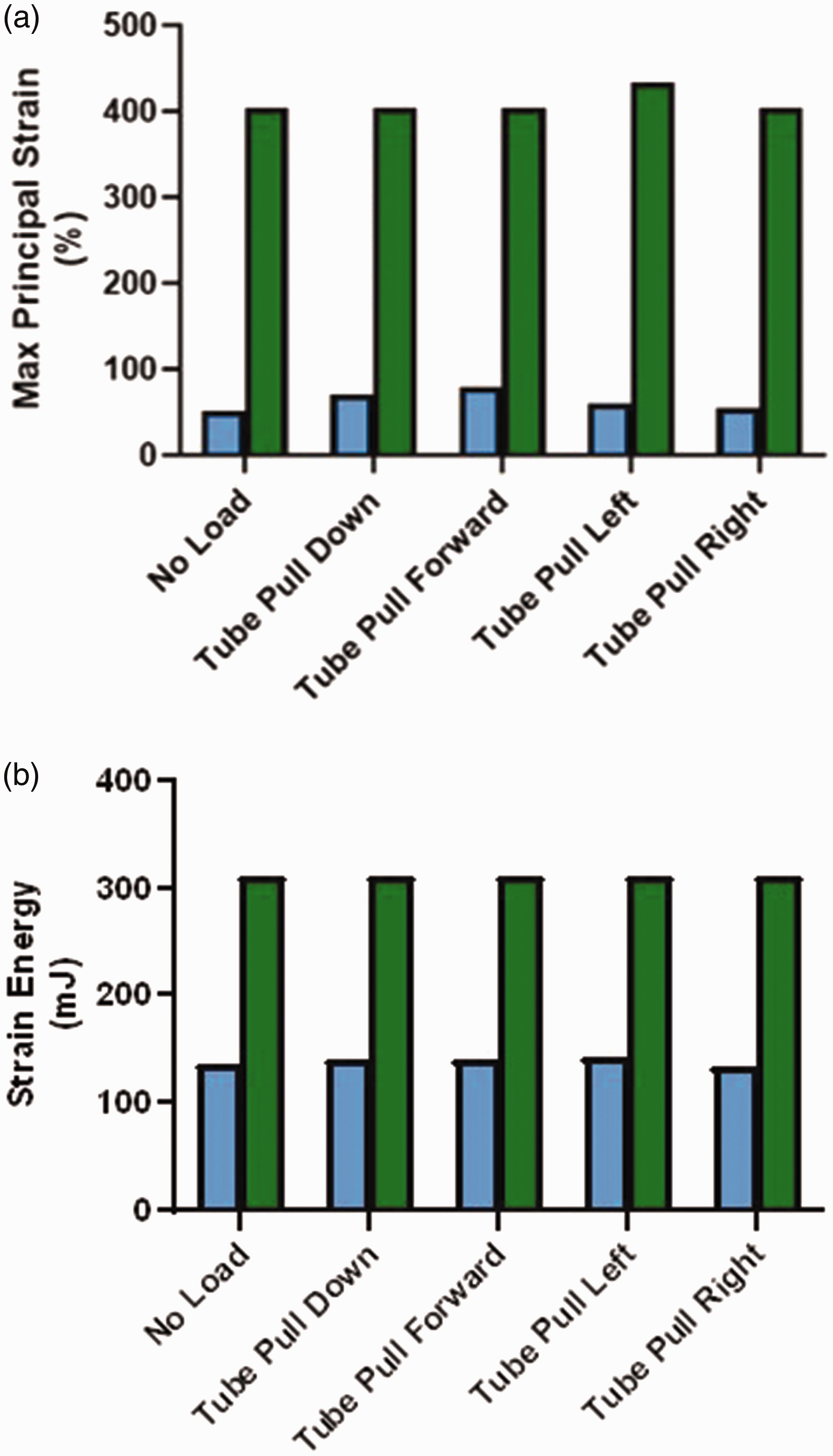
Maximum principle strain and strain energy results. (a) Maximum principal strain. Blue bars represent the nasogastric tube securement with no hard components (NGTS-S). Green bars represent the nasogastric tube securement with hard components (NGTS-H). The conditions modelled were for the tube hanging from the nose with no load or being pulled with 4 pounds of force in the directions shown. (b) Strain energy values. Blue bars represent the NGTS-S device. Green bars represent the NGTS-H device. The conditions modelled were for the tube hanging from the nose with no load or being pulled with 4 pounds of force in the directions shown.
Discussion
Pressure injuries have an impact on patient morbidity and quality of life. 13 In the present study, we investigated the stresses and strains (which could lead to NGaPU development) imparted to tissues by two different NGTS devices. To accurately model these stresses and strains using FEA, an anatomically correct, open-source CT scan image was obtained. Stress/strain data were measured using actual devices and imported into Abaqus software. Our data showed that some of the highest tissue strains associated with the use of NGTS-H were observed around the alar rim and columella. This is consistent with the clinical literature whereby the columella are found to be among the most frequently and severely affected sites for MDRPIs. 1 It is believed that the blood supply to the tip of the nose is similar to an end artery which may make it more susceptible to necrosis. 1
The FEA model visually demonstrated that the maximum principal strain values were at least 5-fold less when the NGTS-S device was used. The results also showed that the TSE density was over 2-fold less when the NGTS-S device was used. Clinically, high strain levels could be more damaging to the skin, especially friable skin or the delicate mucus membranes of the nares. In vitro, high levels of strain have been associated with cellular damage and death.10,11 Patient outcome goals should therefore be centred around providing the least amount of time under high strain levels as possible. In the case of securement of an NG tube, using a device such as the NGTS-S which minimises the strain imparted to the tissue is a good first step.
The literature suggests that securement of NG tubes should be without tension and should allow the tube to free float in the nare.14–16 The new NGTS-S device modelled herein does not hold the tube as tightly against the nare as other devices such as the NGTS-H. The NGTS-S device imparts less strain and stresses to the tissue during use and may provide clinicians an option for securement of an NG tube that is less damaging.
Limitations
This in silico study revealed important biomechanics associated with the use of NGTS devices; however, some limitations exist. All FEA tissue models assume homogeneity of the tissue whereas actual tissue has multiscale variations in these properties. The net result of this is likely that our strains may be overpredicted. However, the relative comparison between the NGTS devices is still valid and the results provide important insights. In the current study, we used average physical values for tissue from the literature. 12 However close the FEA model inputs may be to real tissues, the model cannot recapitulate the clinical complications of moisture, pH-associated tissue changes, and patient comorbidities. All of these factors certainly contribute to the speed and severity of tissue injury under continuous strain. Future studies should consider the effects of these varying parameters to represent the spectrum of tissue strengths that may be exposed to NGTS devices. It would enhance the current study findings if in vivo experiments and clinical validation of the model predictions were carried out.
Conclusion
Use of NG tubes can lead to significant pressure injury. As such, the securement of an NG tube should be without tension and should allow the tube to freely float in the nare. Currently available NGTS devices either include hard plastic connectors or have no hard components. An FEA model was used to assess the differences in potential stress and strain between hard and soft NGTS devices. The new NGTS-S device showed less strain and stress imparted to the tissues in FEA modelling and may provide clinicians with an option for securement of an NG tube that is less likely to lead to MDRPI.
Supplemental Material
sj-pdf-1-imr-10.1177_03000605241264799 - Supplemental material for Assessment by finite element analysis modelling of tissue strains associated with the use of two different nasogastric tube securement devices
Supplemental material, sj-pdf-1-imr-10.1177_03000605241264799 for Assessment by finite element analysis modelling of tissue strains associated with the use of two different nasogastric tube securement devices by Amy K. McNulty, Robert P. Wilkes, Kimberly Schommer and James Sieracki in Journal of International Medical Research
Footnotes
Acknowledgement
We deeply appreciate the help of Julie Robertson in the review of this manuscript.
Author contributions
AM, RW, KS, and JS conceived of the experiment and design, contributed to the article, and revised sections of the manuscript. RW conducted the actual FEA modelling.
Data availability
The data that support the findings of this study are available from the corresponding author (AKM) upon reasonable request.
Declaration of conflicting interests
The authors of the above paper are all employees of Solventum Corporation.
Funding
This research received no specific grant from any funding agency in the public, commercial, or not-for-profit sectors.
References
Supplementary Material
Please find the following supplemental material available below.
For Open Access articles published under a Creative Commons License, all supplemental material carries the same license as the article it is associated with.
For non-Open Access articles published, all supplemental material carries a non-exclusive license, and permission requests for re-use of supplemental material or any part of supplemental material shall be sent directly to the copyright owner as specified in the copyright notice associated with the article.