
Abstract
Objective
Tension band plating has recently gained widespread acceptance as a method of correcting angular limb deformities in skeletally immature patients. We examined the role of biomechanics in procedural failure and devised a new method of reducing the rate of implant failure.
Methods
In the biomechanical model, afterload (static or cyclic) was applied to each specimen. The residual stress of the screw combined with different screw sizes and configurations were measured and compared by X-ray diffraction. With regard to static load and similar conditions, the stress distribution was analyzed according to a three-dimensional finite element model.
Results
The residual stress was close to zero in the static tension group, whereas it was very high in the cyclic load group. The residual stress of screws was significantly lower in the convergent group and parallel group than in the divergent group. The finite element model showed similar results.
Conclusions
In both the finite element analysis and biomechanical tests, the maximum stress of the screw was concentrated at the position where the screws enter the cortex. Cyclic loading is the primary cause of implant failure.
Keywords
Introduction
Temporary hemiepiphysiodesis is an attractive operative procedure for correction of angular deformities at the metaphyseal level in skeletally immature patients. 1 All of the various instruments used for the procedure, such as staples and the tension band plates, have the ability to temporarily arrest the growth of the target physis, with progressively normal growth occurring out to the far edge of the growth plate. Tension band plating (TBP), first introduced by Stevens, 1 involves the use of a non-locking plate and screws. Compared with the traditional staple method, this technique has been used more frequently in the past decade, is technically easy and minimally invasive, and has a faster rate of correction.2–4 However, failure of this technique is not rare. A Pediatric Orthopaedic Society of North America questionnaire performed in August 2007 showed that 15% of surgeons had encountered failure of the tension band plate. 5 The straight plate rarely matches the convex contour of the physis and metaphysis. The poorly mounted implant system is relatively unstable and may produce a nonuniform stress distribution on the growth plate and stress concentration on the screws. 5 Thus, fixation failure may occur, especially in patients with an abnormal physis. 6 In their series of 31 cases, Schroerlucke et al. 7 reported a 26% fixation failure rate in the treatment of angular deformities of the lower limb. In addition, improper screw placement and cyclic loading during ambulation may be crucial factors in breakage.5,7,8 However, none of these potential factors have been verified in clinical studies.
We examined the role of putative biomechanical factors in implant failure to provide new data for improvement of implant designs. For this purpose, we developed a biomechanical and a three-dimensional (3D) finite element model (FEM) to analyze the stress response over the surface of the screws and cortex.
Materials and methods
Ethics
This study was approved by the Institutional Review Board/Ethics Committee of Xin-Hua Hospital (reference number: XHEC-D-2018-029) and was conducted according to the ethical principles stated in the Declaration of Helsinki. Written consent was obtained from the patients. All participants declared that they agreed to publication of the data described in the manuscript.
Biomechanical model
We conducted this experiment primarily to assess the effect of loading on different screw positions and lengths. Our experimental model used an ultrahigh-molecular-weight polyethylene (UHMWPE) construct to simulate cortical bone as described by Stitgen et al. 8 A 10-mm wide slice was cut through the UHMWPE to create a gap, which represented the physis (Figure 1). A previous study showed that screw breakage in vivo occurs at the lateral cortex, 5 and we thus assumed that the maximum stress would be located at the point where the screw entered the cortex. (In our pilot test, solid polyurethane foam modeled cancellous bone and a layer of high-density polyethylene simulated cortical bone. Under cyclic load conditions, an impression on the surface of the screw was detected in the place where the screw entered the high-density polyethylene. No significant stress was detected in the place where the screw contacted the foam). Therefore, the presence of metaphyseal trabeculae was ignored in this model. The procedure precisely followed the steps recommended by Stevens 1 in vivo. The surface of the UHMWPE was predrilled to reduce stress while inserting the screw. The tension band plate (Shanghai Puwei Medical Instrument Co., Ltd., Shanghai, China) was then placed across from and perpendicular to the gap, and both screws were tightened alternately. Care was taken to place the plate on the center of the bone model to avoid eccentric placement in terms of tension. All samples were divided into static tension load (SL) and cyclical load (CL) subgroups. Each group was further subdivided by screw length into a 20-mm subgroup (half the length of the model) and 30-mm subgroup (two-thirds the length of the model). The proximal and distal screws were inserted divergently by 30° (n = 6), in parallel (n = 6), or convergently by 30° (n = 6) (Figure 1). The samples with convergent 30-mm screws were excluded because some of the screws penetrated the gap.

Biomechanical model of tension band plating with a 5-mm gap. (a) The screws were inserted convergently. (b) The screws were inserted in parallel. (c) The screws were inserted divergently. The red square dotted line shows the direction of the screws.
In the SL group, 500 N of pure tension was maintained for 10 minutes in a materials testing machine (Zwick, University of Shanghai for Science and Technology, Shanghai, China) (Figure 2). A cyclical load test was performed to simulate a load acting on the implant during ambulation in the CL group.8,9 The machine was used to apply 2 Hz of micromotion at −500 N compression for 10 minutes; this loading protocol produced a peak value of 1000 N/s. The contact-induced residual stress in the screw in contact with the UHMWPE was measured using X-ray diffraction (XRD) (Bruker D8 Advance; University of Shanghai for Science and Technology). Residual stresses were defined as the stresses remaining in the material in the absence of any external forces. The contact-induced residual stress at the rim of the metaphyseal screw hole was measured using XRD after hardware removal. The distance between crystallographic planes was employed as a strain gauge for the residual stress measurement using XRD. The deformations cause changes in the value representing the spatial structure of the lattice planes from the stress-free stage to the new stage depending on the magnitude of residual stress. XRD stress measurement can be a powerful tool for failure analysis or process development studies. The measurements were performed with copper K-alpha radiation. The reflection of titanium alloy at 2theta of 70.631° was used in the residual stress analysis. Lattice strains were measured at six positions (psi values of 0.00, 8.13, 11.54, 14.18, 16.43, and 18.43). The diffraction angle was determined by best fit to the diffraction curves using computer software. The residual stress acting in the direction perpendicular to the long axis of a plate could be calculated according to the sin2ψ method. 10 Leptos software (Bruker-AXS, University of Shanghai for Science and Technology) was used for the residual stress analysis.

Sample setup in the stretcher (black arrow: tensile displacement was observed on the opposite side)
3D FEM
This experiment was conducted primarily to analyze the stress distribution in the screw. Tibial images from a 6-year-old girl were retrieved from a picture archiving and communication system. Bony measurements were obtained using 0.67-mm computed tomography slices from the distal femur to the proximal tibia. The computed tomography scan for this specimen was imported into Mimics medical imaging software, version 10.0 (Materialise, Leuven, Belgium) to extract the geometry of the bone and imported to ABAQUS, version 6.9 (Dassault Systèmes, Providence, RI, USA) to reconstruct a 3D image of the proximal tibia. The most proximal transverse section of bone was oriented to be perpendicular to the mechanical axis of the tibia. The mediolateral (ML) plane was oriented to be parallel to the greatest ML distance of the most proximal tibial transverse section. The anteroposterior plane was oriented to be parallel to a line drawn perpendicular to and passing through the midpoint of the ML plane. The model included the metaphysis (cortex and medullary trabeculae) and subchondral epiphysis. The growth plate was modeled as an irregular gap reconstructed between the epiphysis and metaphysis. A tension band plate made of titanium alloy steel was dimensioned using a two-hole tension band plate with dimensions of 80 mm (length) × 8 mm (width) × 4 mm (depth). The screws were 4.5-mm cortical screws, which are most frequently used in clinical practice. The plate was inserted on the medial aspect of the upper tibia and centered on the perichondrial ring. The plate–bone and screw–bone interfaces were meshed using an eight-node quadratic surface-to-surface element by hard contact, with a coefficient of 0.3. The surface-to-surface contact option in ABAQUS was adopted to simulate the interaction between the plate and bone with assumption of hard contact behavior. The contact surface between the flat plate and epiphysis was modulated to create a flat contact area and ensure complete contact between the bone and plate, while a space was created between the distal plate and metaphysis to mimic the irregular surface of the medial proximal tibial metaphysis. The proximal and distal screws were inserted divergently by 30° (D model), parallel (P model), and convergently by 30° (C model). The screw length was 20 mm (one-third the length of the ML distance) or 30 mm (half the length of the ML distance). The model with convergent 30-mm screws was excluded, as in the biomechanical model. Tension stress was set at 500 N parallel to the mechanical axis of the tibia. Contacts were defined between the screw and bone. During load application, a “tied” interface contact model was used in the screw–bone interface. The element type (C3D10, a 10-node quadratic tetrahedron), analysis type (ABAQUS/Standard), and parameters of each component of the 3D FEM are shown in Table 1. 11
Parameters of each specimen.

Statistical analyses
Statistical significance was obtained by the rank-sum test calculation to compare the residual stress among different subgroups, and 95% confidence intervals for pairwise differences were calculated. A p-value of <0.05 was considered statistically significant.
Results
Biomechanical model
The outputs of the static tension test and cyclic load test were measured and are shown in Figure 3. The contact-induced residual stress of the screw surface was then measured by XRD. In the SL group, the residual stress of the screw contact area was close to zero. The results in the CL group are shown in Table 2. The stress was compressive because of the negative value of the residual stress. There was no significant difference between the divergent 20-mm and 30-mm screw subgroups, between the parallel 20-mm and 30-mm screw subgroups, or between the convergent 20-mm and parallel 20-mm screw subgroups. The residual stress in the divergent 20-mm screw subgroup was significantly higher than that in the convergent 20-mm screw subgroup (p < 0.001) and parallel 20-mm screw subgroup (p < 0.001) (Table 2).
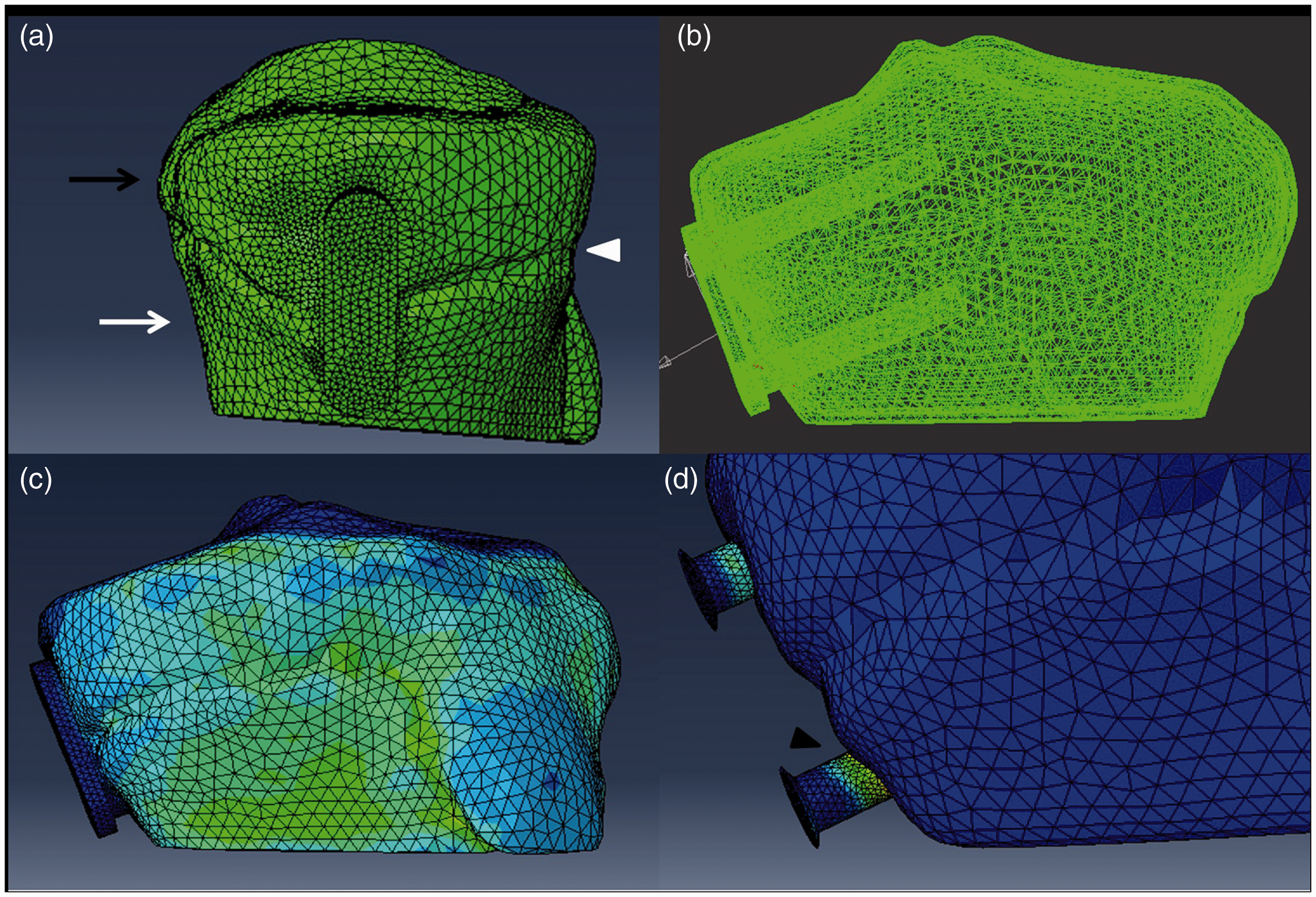
Three-dimensional (3D) finite model of tension band plating. (a) Lateral proximate tibia and tension band plate of the 3D finite model. (b) Anteroposterior proximate tibia and tension band plate of the 3D finite model. (c, d) Stress distribution of the model under 500 N of tension stress. Black arrow: subchondral epiphysis, white arrow: metaphysis (cortex bone), white triangle: position of growth plate, black triangle: maximum stress located at the position where the shank enters the cortex.
Residual stress in different groups after cyclic tension loading (unit: MPa).

SD: standard deviation, 20P: subgroup with parallel 20-mm screw, 30P: subgroup with parallel 30-mm screw, 20D: subgroup with divergent 20-mm screw, 30D: subgroup with divergent 30-mm screw, 20C: subgroup with convergent 20-mm screw, NA: not available.
FEM
The FEM was designed to reveal the stress distribution of the screw with a 500-N growth force. All models demonstrated that the maximum load was at the point where the metaphyseal screw entered the cortical bone (Figure 3). Comparison of the maximum stress in the three groups revealed the following results: model with the convergent 20-mm screws (4.83 MPa) <parallel 20-mm screws (7.28 MPa) < divergent 20-mm screws (12.49 MPa). The orientation of screw insertion had a significant effect on the derived stress calculations. The maximum stress of the model with divergent 30-mm screws (10.25 MPa) was 18% lower than that of the model with divergent 20-mm screws (12.49 MPa), and the maximum stress of the model with parallel 20-mm screws (7.28 MPa) was 7% lower than that of the model with parallel 30-mm screws (7.8 MPa). The screw length had no significant effect on the derived stress calculations (Figure 4).
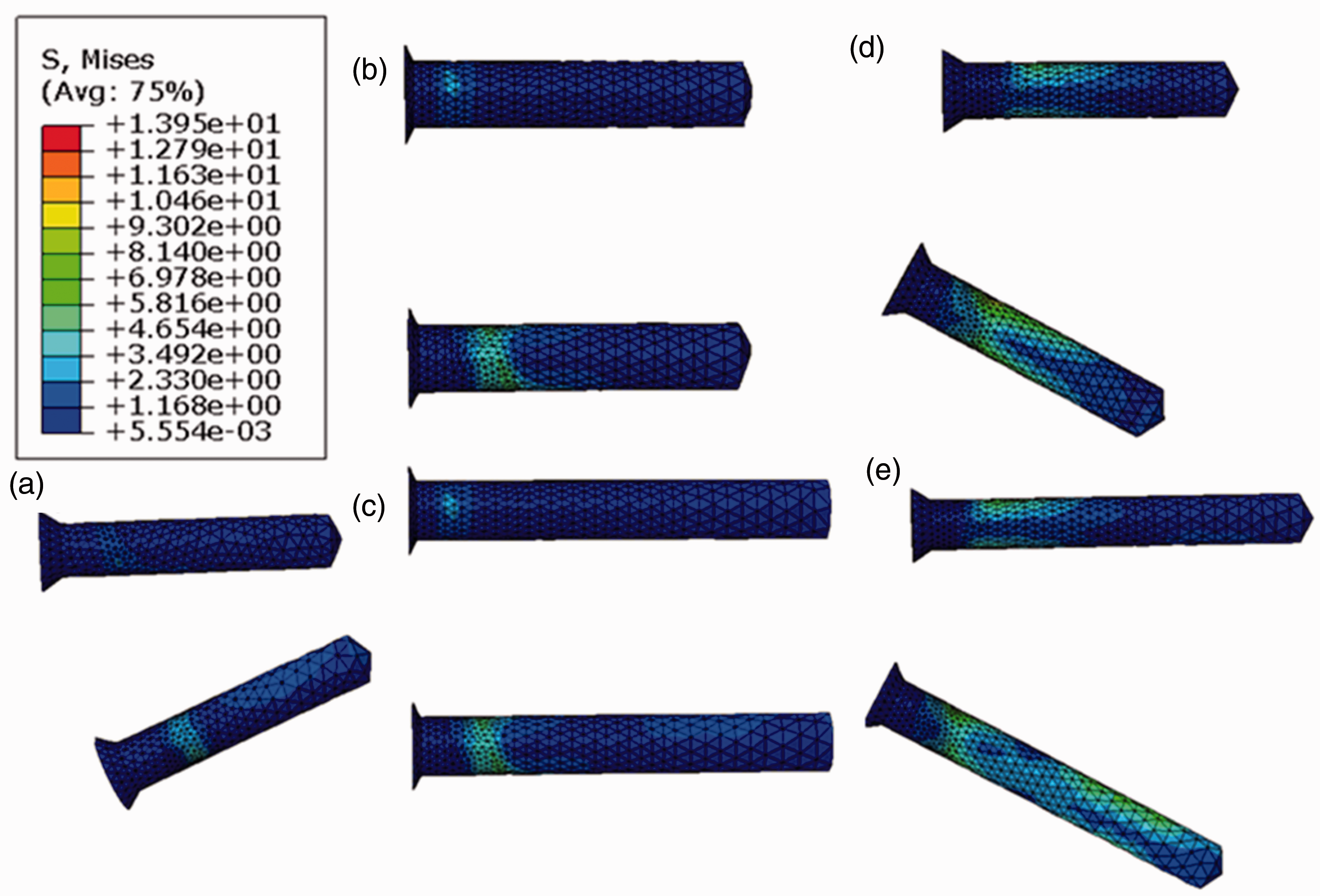
Stress distribution of screws of different lengths and subgroups. (a) The C model with 20-mm convergent screws. (b) The model with 20-mm parallel screws. (c) The model with 30-mm parallel screws. (d) The model with 20-mm divergent screws. (e) The model with 30-mm divergent screws. Upper screw: epiphyseal screw, lower screw: metaphyseal screw, red arrow: location of maximum stress. The maximum stress of (a), (b), (c), (d), and (e) was 4.83, 7.28, 7.80, 12.49, and 10.25 MPa, respectively.
Discussion
Compared with staple techniques, TBP appears to reduce the rate of implant failure. However, reports of screw breakage are not uncommon, especially in obese patients.5,6 To our knowledge, no study has revealed the relationship between the biomechanical characteristics of the tension band plate and implant failure. In this study, a biomechanical test and a 3D model of the proximal tibia were employed to estimate the effect of different factors on the stress distribution in the screw. In the biomechanical tests, two UHMWPE blocks were used to simulate the bone and growth plate. Because of the known clinical site of screw failure, we considered it reasonable to omit a detailed reconstruction of the epiphysis, cancellous bone, and surrounding soft tissue in this model. The width of this bone model was 6 cm, which was the same as the parameter of the FEM. We acknowledge that this model does not completely simulate physiological conditions; nevertheless, we contend it to be representative of the tension band principle (loading force induces compression of the near cortex and tension in the far cortex). 1 This model was produced easily and in a more controllable way than cadaveric or animal bone models. 8 The experimental design and parameters in our 3D FEM analysis were similar to those of the biomechanical test. The following four questions were explored in our study.
Does static or cyclical loading cause implant failure?
Based on implant deformation in vivo, Bylski-Austrow et al. 12 defined 500 N as the growth force generated by the physeal plate. In our study, however, contact-induced impressions in the plate were not observed in the SL subgroup. We predicted that under 500 N of static tension, the stress is far less than the yield stress of titanium screws; 13 consequently, the residual stress cannot be measured after tension removal. The maximum stress (12.49 MPa) of all FEMs was also far lower than the yield stress of the titanium alloy screws. In the CL group, a cyclical load of 1000 N/s at a frequency of 2 Hz was employed to simulate walking conditions. According to the law of conservation of momentum, the peak stress should be >500 N at the moment when the UHMWPE and screw interact with each other. Our residual stress measurement result verified that this force is strong enough to cause screw fatigue and finally breakage. In the clinical environment, patients are encouraged to partake in daily activities after surgery without casts or braces. However, cyclical loading during activities such as walking, running, and jumping may risk screw fatigue and fracture. This risk is acknowledged by other authors who have suggested that although exercise is indispensable to stimulate skeletal growth, excessive exercise should be avoided,5,7,8 especially by patients with risk factors for implant failure (e.g., obesity).
Which screw position is most susceptible to breakage?
The results of both the biomechanical testing in the CL subgroup and the FEM analysis showed that stress was concentrated primarily at the position where the metaphyseal screw entered the cortical bone; we believe that this explains why most screw breakages occur at this position in the clinical setting.5,6 The FEM analysis showed that stress in the metaphyseal screw was higher than that in the epiphyseal screw. We consider that the greater elastic modulus in the cortical bone and the offsetting of the metaphyseal screw played an important role. A previous study also showed that the stress on the plate and screws was high if the implant did not conform closely to the bone surface. 14
Does the length of the screw influence the stress distribution?
The screw length was 20 mm (one-third the width of the physis) and 30 mm (half the width of the physis) in our study because this is the range of screw lengths in vivo. In the FEM analysis, the maximum stress in the screw was similar in both groups and between these two screw lengths. In the biomechanical tests, there was no significant difference between these screw lengths in the CL subgroup (Table 2). These results indicate that the screw length does not seem to play an important role in stress concentration in the screw, a finding verified by Raluy-Collado et al. 15 In theory, a longer screw should provide stronger hold within bone; however, a long screw may increase the risk of physeal penetration. The choice of screw length should be determined by anatomical considerations.
Does the method of screw placement influence the rate of screw breakage?
In the FEM analysis, the maximum stress of the divergent models was lower than that of the convergent model. Similarly, in the biomechanical tests, the residual stress in the subgroup with a divergent screw was lower than that in the subgroup with a convergent screw. The original orientation of screw insertion is associated with the potential stress in the screw. In addition, the screws were free to diverge under tension in the C and P groups, whereas the screws were prevented from diverging further by the plate in the D group. Free motion of screws is likely to reduce the maximum stress at the moment of peak tension, assuming that during the process of hemiepiphysiodesis the proximal and distal screws slowly diverge because of the effect of the growth force. Once both screws diverge to approximately 30°, the plate limits further screw movement and the tension band behaves as a “staple”; in this situation, the stress on the screw is higher. Placement of proximal and distal screws perpendicular to or slightly convergent with each other for the purpose of a relatively long period of a low risk of implant failure seems sensible. Placing the screws in a very convergent position should be avoided because of the risk of physeal injury. Schoenleber et al. 16 also suggested that the screw configuration is very important to the final treatment results.
Our study has several limitations. First, during biomechanical testing, the model was not entirely anatomical; we did not use cadaveric or animal tibial bone. The cyclic load of the model was not entirely physiologic. During ambulation, the force acting on the implant is multiaxial and variable. Muscle and other soft tissue around the growth plate play an important role in this process. A more physiologic model needs to be built in future studies. Second, it is difficult to mimic the process of growth force action on the screw using a materials testing machine. Third, the stresses in the FEM analysis were elastic forces, while the screw stress in the biomechanical tests was inferred from the residual plate stress. These two types of stress are quite different: the elastic force in the screw might disappear after force removal, while residual stress might accumulate as a result of elastic force application. Both might qualitatively reflect the stress distribution and provide valuable insight into clinical observations.
Compared with mechanical models, a 3D FEM has the advantage of allowing an abundant number and variety of “specimens” to be built and tested. 17 It can also provide additional information such as the stress distribution through the bone and implant. However, generating an appropriate and valid model may be difficult because of the complex bone–implant construct and mechanical environment. Conversely, although a mechanical model provides the most direct and obvious way to obtain information, it can be expensive and unwieldy and suffers from specimen variability and issues of repeatability. Therefore, an individualized FEM may be more acceptable with the development of validation techniques, and its use may become more popular than mechanical models in future.
Conclusions
Cyclical loading is the primary cause of implant failure. In both the FEM analysis and biomechanical tests of this study, maximum stress occurred in the position where the screws entered the cortex. The screw length does not appear to play an important role in influencing the stress distribution. Inserting screws in a non-divergent direction might reduce the maximum stress in the screw and ultimately reduce the rate of screw breakage. These findings will help the surgeon determine the optimal method with which to place the screws. The present study has also provided mechanical evidence for designing a new TBP system. FEM analysis provides more accurate information about the stress distribution, and the development of individualized models will contribute even more information in the future.
Footnotes
Acknowledgements
The authors acknowledge the writing assistant center in the Children’s Mercy Hospital of Kansas City (64108 MO, USA) as writing assistant.
Declaration of conflicting interest
The author(s) declared no potential conflicts of interest with respect to the research, authorship, and/or publication of this article.
Funding
The author(s) disclosed receipt of the following financial support for the research, authorship, and/or publication of this article: This work was financially supported by the National Natural Science Foundation of China (Grant No. 81501930) and Shanghai Jiaotong University Medical Engineering interdisciplinary projects (Grant No. YG2017MS69).