
Abstract
This paper introduces MILUV, a Multi-UAV Indoor Localization dataset with UWB and Vision measurements. This dataset comprises 217 minutes of flight time over 36 experiments using three quadcopters, collecting ultra-wideband (UWB) ranging data such as the raw timestamps and channel-impulse response data, vision data from a stereo camera and a bottom-facing monocular camera, inertial measurement unit data, height measurements from a laser rangefinder, magnetometer data, and ground-truth poses from a motion-capture system. The UWB data is collected from up to 12 transceivers affixed to mobile robots and static tripods in both line-of-sight and non-line-of-sight conditions. The UAVs fly at a maximum speed of 4.418 m/s in an indoor environment with visual fiducial markers as features. MILUV is versatile and can be used for a wide range of applications beyond localization, but the primary purpose of MILUV is for testing and validating multi-robot UWB- and vision-based localization algorithms. The dataset can be downloaded at
Introduction
Autonomous vehicles rely on the fusion of multiple complementary sensors to be able to perceive and navigate their environment. Sensor fusion is particularly critical in multi-robot scenarios, potentially aided by communication between robots to allow them to perform tasks collaboratively, such as in infrastructure inspection, helping warehouse operators, or moving heavy objects over large distances. For example, autonomous road vehicles typically use a combination of radar, LiDAR, cameras, and global navigation satellite system (GNSS) receivers to localize themselves and map their environments. Unmanned aerial vehicles (UAVs), however, are more restricted in the sensors they can use, particularly when flying indoors. This has led to an increased interest in vision algorithms and the recent adoption of ultra-wideband (UWB) radios to navigate in GNSS-denied environments. Cameras and UWB, unlike LiDAR sensors, are relatively inexpensive, low-power, and lightweight. Moreover, UWB provides a means of communication between multiple UAVs.
Cameras and UWB sensors can be thought of as complementary. Cameras provide information about the environment and can be used for object detection and segmentation, including the detection of the relative pose of neighbouring robots. However, cameras are limited by their field-of-view (FOV) and require favourable lighting conditions. Meanwhile, UWB radios do not depend on lighting conditions and, with appropriate antennas, are largely omni-directional, so that they can provide information to robots outside a camera’s FOV. They can be used to exchange messages between transceivers over short distances with precise timestamps, as well as record the wireless channel state between the transceivers, in the form of channel impulse responses (CIRs). This information, although not as rich as for cameras, can then be used in particular to provide range measurements to fixed anchors with known positions and/or to neighbouring robots, from which relative poses can also be estimated. However, although UWB is designed to be relatively robust to multipath propagation effects, these range measurements are still affected by non-line-of-sight (NLOS) conditions, when an object obstructs the direct path between the two communicating UWB transceivers.
As such, the necessity to address indoor localization and mapping algorithms using vision and UWB simultaneously is evident. Utilizing vision and UWB for localization are two active fields of research where a lot of progress has been achieved, but the low-level complexities of each sensing modality are typically addressed separately and sensor information is only fused at a high level. To foster research at the intersection of these two actively growing fields, this paper presents MILUV, a Multi-UAV Indoor Localization dataset with UWB and Vision measurements. This dataset provides low-level UWB data such as raw timestamps, CIR data, and received signal power alongside measurements from a stereo camera, with the goal of supporting the development of advanced algorithms for multi-robot online localization and for camera and UWB calibration.
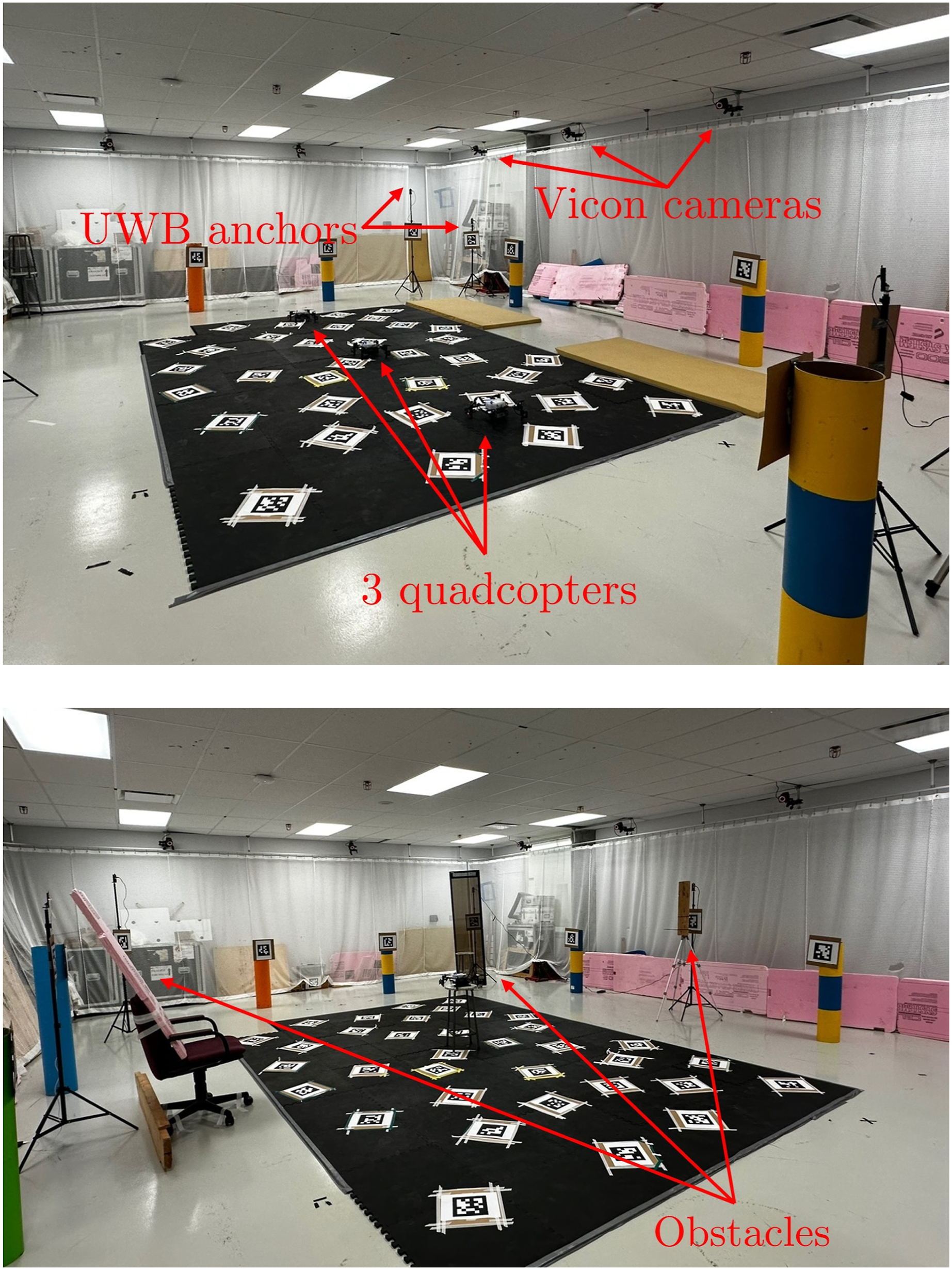
The MILUV dataset includes data collected using three quadcopters, each equipped with several sensors shown in Figure 1, primarily a stereo camera and two UWB transceivers. The environment, shown in Figure 2, is fitted with six UWB transceivers, for a total of 12 between anchors and robots. Alongside the cameras and the UWB transceivers, MILUV includes data from a downward-facing monocular camera, a laser rangefinder providing height measurements, a magnetometer, and two inertial measurement units (IMUs) on each quadcopter. A variety of different trajectories are recorded, including static experiments and other special trajectories with and without obstacles intended for calibrating and characterizing sensor parameters. A different combination for the number of robots, the number of UWB transceivers per robot, and the UWB anchor constellation is used in each experiment. In total, 173 GB of data is collected for a total of 217 minutes of cumulative flight time. The dataset can be downloaded at The sensors equipped on the Uvify IFO-S quadcopter. The environmental setup, with (top) and without (bottom) obstacles.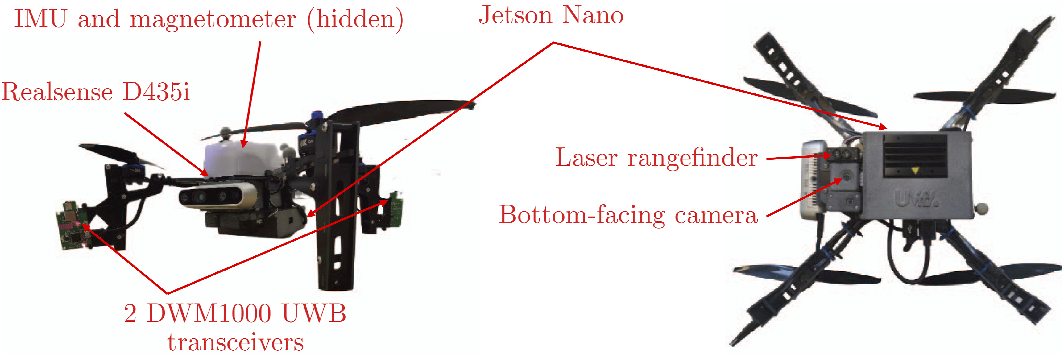
To aid with the usage of MILUV, the data has been benchmarked against standard estimation tools, including pose estimation by fusing the UWB and IMU measurements using an extended Kalman filter (EKF), visual-inertial simultaneous localization and mapping (SLAM) using VINS-Fusion (Qin et al., 2019), and fusing visual-inertial odometry (VIO) with UWB measurements in an EKF for pose estimation. Additionally, a development kit is provided at
In summary, the main contributions of this dataset are as follows: • A UWB dataset with three quadcopters, each equipped with two UWB transceivers, a stereo camera, two IMUs, a downward-facing camera, a magnetometer, and a height laser rangefinder. Ground-truth pose data is collected for each quadcopter using a Vicon motion capture system. • Low-level UWB data recorded with a double-sided two-way ranging (DS-TWR) protocol, time-synced with the vision data and all other sensors. This includes the raw timestamps, CIR data, received signal power, and clock skew measurements, in scenarios with and without obstacles for characterizing the effect of NLOS conditions. • Passive listening measurements recorded by UWB radios not participating in a given DS-TWR exchange, which provide information at no additional cost and can be used to develop new algorithms for multi-robot teams.
Given the fact that MILUV exposes to the public a host of data that is typically underutilized in localization applications and robotics, an indoor setting is chosen for MILUV. There are many complications associated with outdoor settings with long sequences, including but not limited to obtaining accurate ground truth data, eliminating dynamic objects from the scenes, and ensuring consistent conditions between experiments. MILUV reduces the barrier to entry for the usage of low-level UWB data, and it does so by providing data in a simple setting with accurate ground truth data. This will contribute to the effort of bridging the gap between existing localization algorithms and ones that utilize more information available from UWB sensors, which is currently an understudied topic. The hope is that MILUV will foster further research in this direction, eventually bringing the field to a point where outdoor experimentation and testing using multiple vehicles will be feasible.
Related work
Public UWB and vision localization datasets relevant to MILUV. The datasets providing both UWB and vision data in the same experiments appear twice and are formatted in italics.
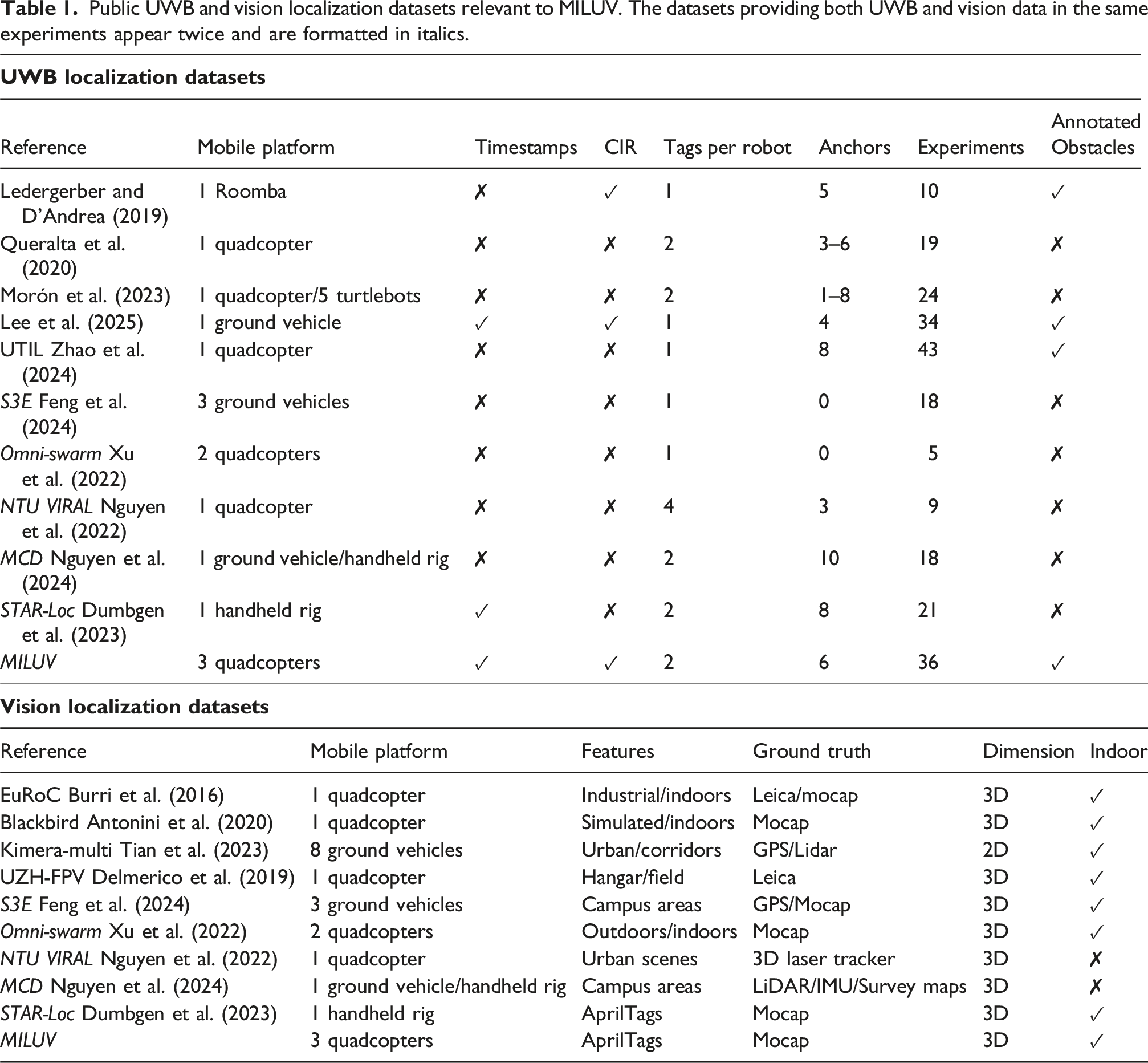
The publicly available datasets generally have only one mobile platform for data collection, such as Queralta et al. (2020), Lee et al. (2025), and UTIL (Zhao et al., 2024) for UWB, and EuRoC (Burri et al., 2016), Blackbird (Antonini et al., 2020), and UZH-FPV (Delmerico et al., 2019) for vision. MCD (Nguyen et al., 2024) uses a quadcopter in some experiments, and a handheld rig in other experiments, and provides both UWB and vision data in large-scale outdoor campus areas. However, the topic of multi-robot localization is growing in importance, where teams of robots need to perform tasks collaboratively. As such, Tian et al. (2023) and Feng et al. (2024) provide comprehensive datasets with ground vehicles equipped with cameras and other sensors in different environments. Meanwhile, Morón et al. (2023) provide range measurements between five ground vehicles, each equipped with a single UWB transceiver. The dataset published alongside Omni-swarm (Xu et al., 2022) includes UWB measurements from two communicating UAVs, each equipped with one UWB transceiver. To the authors’ knowledge, there is no dataset with three or more UAVs equipped with UWB transceivers, despite UWB being a great fit for multi-UAV applications as it is a lightweight and low-power technology that provides a medium for robots to communicate. Data from three or more robots is necessary to validate algorithms that deal with robots that can communicate with some, but not all, of their neighbours.
The majority of UWB localization datasets provide only high-level UWB information, typically range measurements using some ranging protocol, such as two-way ranging (TWR) as in Queralta et al. (2020), or time-difference-of-arrival (TDoA) as in UTIL (Zhao et al., 2024). For the localization datasets mentioned in Table 1, only Lee et al. (2025), Ledergerber and D’Andrea (2019), and STAR-LOC (Dumbgen et al., 2023) provide some lower-level UWB information. In Lee et al. (2025), low-level UWB information from 1 ground robot with 4 anchors is provided alongside IMU and GNSS data. Meanwhile, Ledergerber and D’Andrea (2019) provide CIR data to complement the ranging information and STAR-LOC includes the raw timestamps used to compute the range measurements. MILUV builds on these by providing range measurements, the raw timestamps, CIR data, as well as other low-level UWB information such as the received signal power and passively-received messages between multiple robots in order to develop and evaluate advanced localization algorithms that utilize more information made available by the UWB transceivers.
Despite not providing low-level UWB information, NTU VIRAL (Nguyen et al., 2022) is the dataset most similar to MILUV, as it involves a UAV, includes multiple UWB tags per robot, and includes both UWB and vision information. NTU VIRAL provides an alternative to MILUV for a single-robot application outdoors, whereas MILUV goes beyond NTU VIRAL by providing multiple ranging robots, providing low-level UWB information, and adding experiments with obstacles. The presence of AprilTags and a motion capture system makes MILUV a good candidate for the evaluation of localization algorithms. Also similar to MILUV is STAR-Loc (Dumbgen et al., 2023), where the same UWB hardware as in MILUV is used. MILUV can be seen as the multi-robot extension of STAR-LOC, with additional sensors, additional UWB data, non-line-of-sight measurements, and more experiments.
Notation
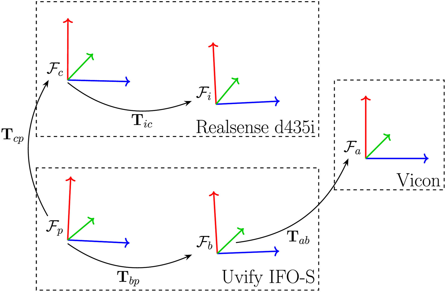
Throughout this paper, a bold upper-case letter such as • an absolute or world frame • a body-fixed frame • a camera-fixed frame • an IMU frame for the Pixhawk IMU • an IMU frame for the camera IMU Sensor frames and their relative transforms.
Moreover, a vector resolved in reference frame α is denoted as
Environment
Flight arena
For the duration of the data collection, the quadcopters are within an approximate 4 m × 4 m × 3 m subsection of an enclosed flight arena. The arena has a Vicon motion capture system comprising 12 cameras. The experimental setup is depicted in Figure 2.
UWB anchors
The dataset includes experiments with 6 UWB anchors with anchor IDs 0 through 5, and with 3 different anchor constellations, shown in Figure 4. The primary constellation consists of anchors at varying heights, evenly spaced around the quadcopters’ operating area. The second constellation consists of anchors at the same positions as the primary constellation, but with each transceiver at the same height. The third constellation consists of three clusters of two anchors at varied heights. The location of each anchor is determined using the Vicon motion capture system, and is provided in the development kit at The three anchor constellations used in the data collection of MILUV.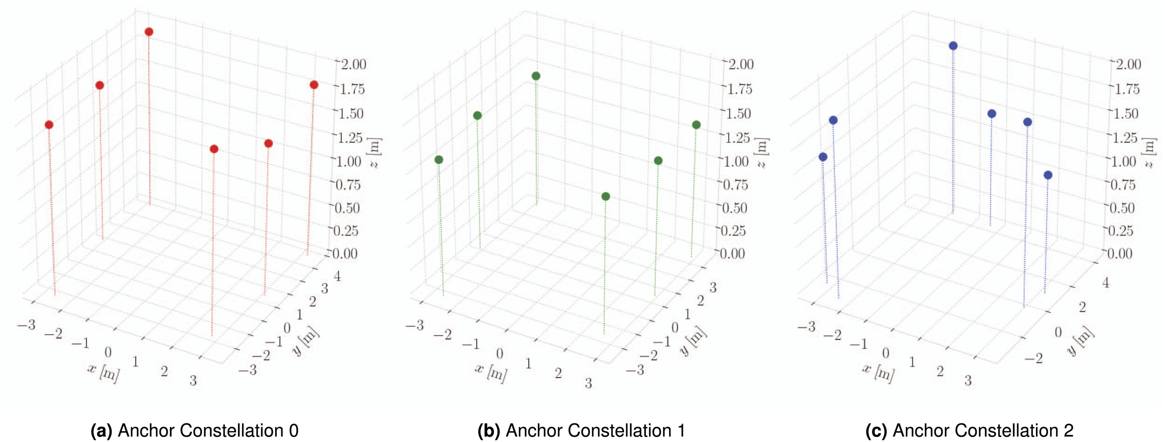
Visual features
The arena is fitted with 48 36h11 AprilTags (Olson, 2011) with 35 tags affixed to the ground, 7 to static objects, and 1 below each of the 6 UWB anchors. The location of each AprilTag is determined using the Vicon motion capture system, and the results are shown in Figure 5, and provided in the development kit at Positions of AprilTags used in the collection of this dataset.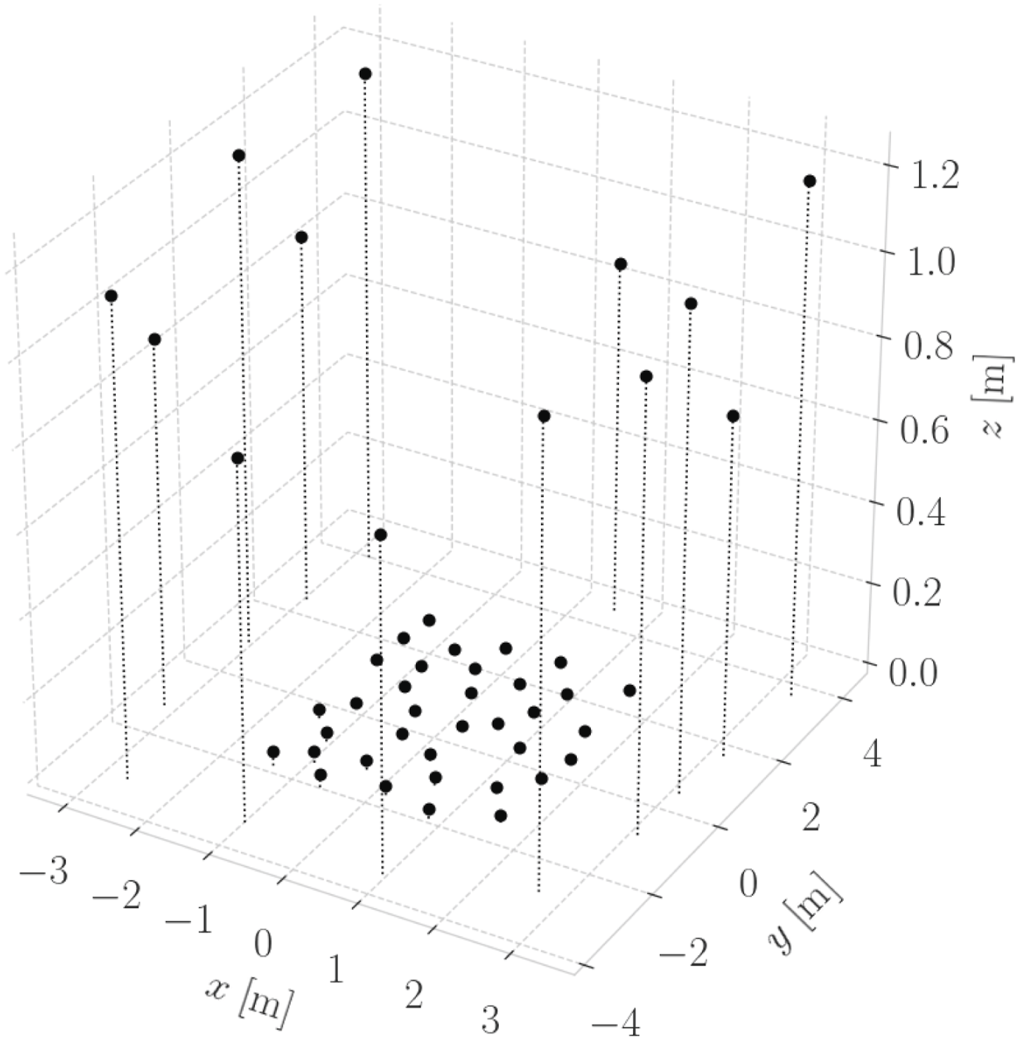
Sensor setup
The quadcopters
The MILUV dataset comprises measurements from three Uvify IFO-S quadcopters. Each quadcopter is equipped with an IMU, a front-facing Intel Realsense D435i stereo camera, an integrated downward facing camera, and two UWB transceivers, depicted in Figure 1. The onboard computer is an NVIDIA Jetson Nano, and the flight controller is a Pixhawk 4 microcontroller running PX4 autopiloting software. The sensor frames and their relative transformations are illustrated in Figure 3.
Ultra-wideband transceivers
A main feature of this dataset is the availability of low-level data available from the UWB transceivers, such as the raw timestamps, received signal power, clock skew measurements, and the channel impulse response. In this section, details regarding the custom hardware and firmware utilized for collecting the UWB data are discussed.
Hardware
Each UAV has two custom-made UWB modules mounted on diagonally opposing legs. These transceivers are labelled 10, 11, 20, 21, 30, and 31, with the first digit representing the robot to which each transceiver is attached, and the second digit differentiating the transceivers on an individual robot. The custom-built UWB boards, shown in Figure 6, are built around the DWM1000
1
UWB transceiver, which is a commonly available and used transceiver. The use of the DWM1000 module with a custom-built board allows complete customizability and accessibility of the DWM1000 microprocessor’s registers. Furthermore, as these boards will be placed on medium-sized quadcopters, they are designed to be compact and lightweight, measuring at 32 mm × 49 mm and weighing just 8 g. Custom-made board fitted with a DWM1000 UWB transceiver.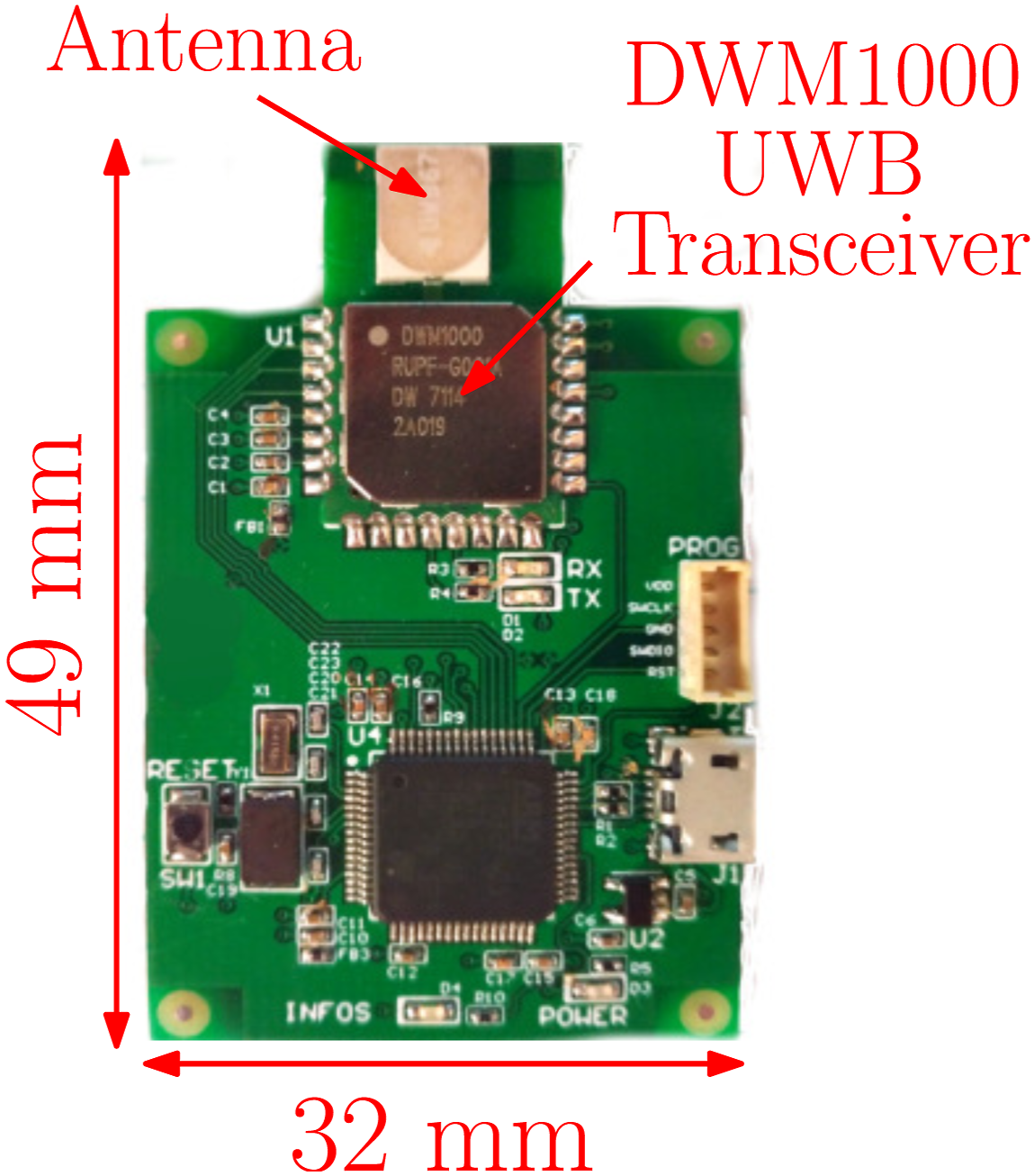
Custom firmware for these transceivers is written in
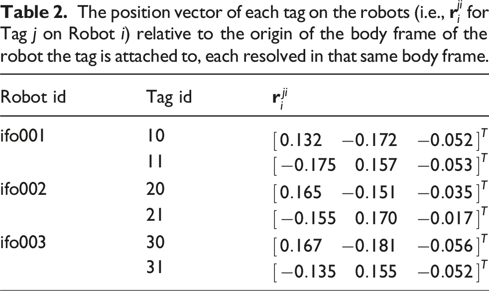
The position vector of each tag on the robots (i.e.,
Ranging protocol
The ranging protocol refers to the sequence of transmissions and receptions between UWB transceivers to compute a range measurement. The ranging protocol used in MILUV is a variation of the standard double-sided two-way ranging (DS-TWR) protocol, based on Shalaby et al. (2023). As shown by the green arrows in Figure 7, in a ranging transaction between a pair of transceivers, an initiating transceiver transmits a message to a neighbouring transceiver, who responds with two messages. Both transceivers timestamp in their own clocks all message transmission and reception instances, where transmission and reception timestamps are denoted The DS-TWR protocol used in MILUV, showing an instance where Transceivers i and j are ranging with each other and a Transceiver ℓ is passively listening on the messages. After every ranging transaction, an information message shown here in red is transmitted by the transaction initiator, here Transceiver i, to share timestamps 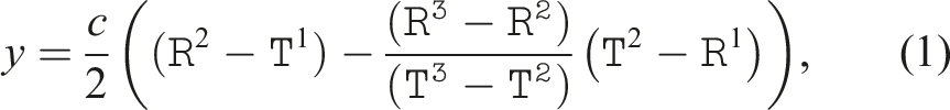
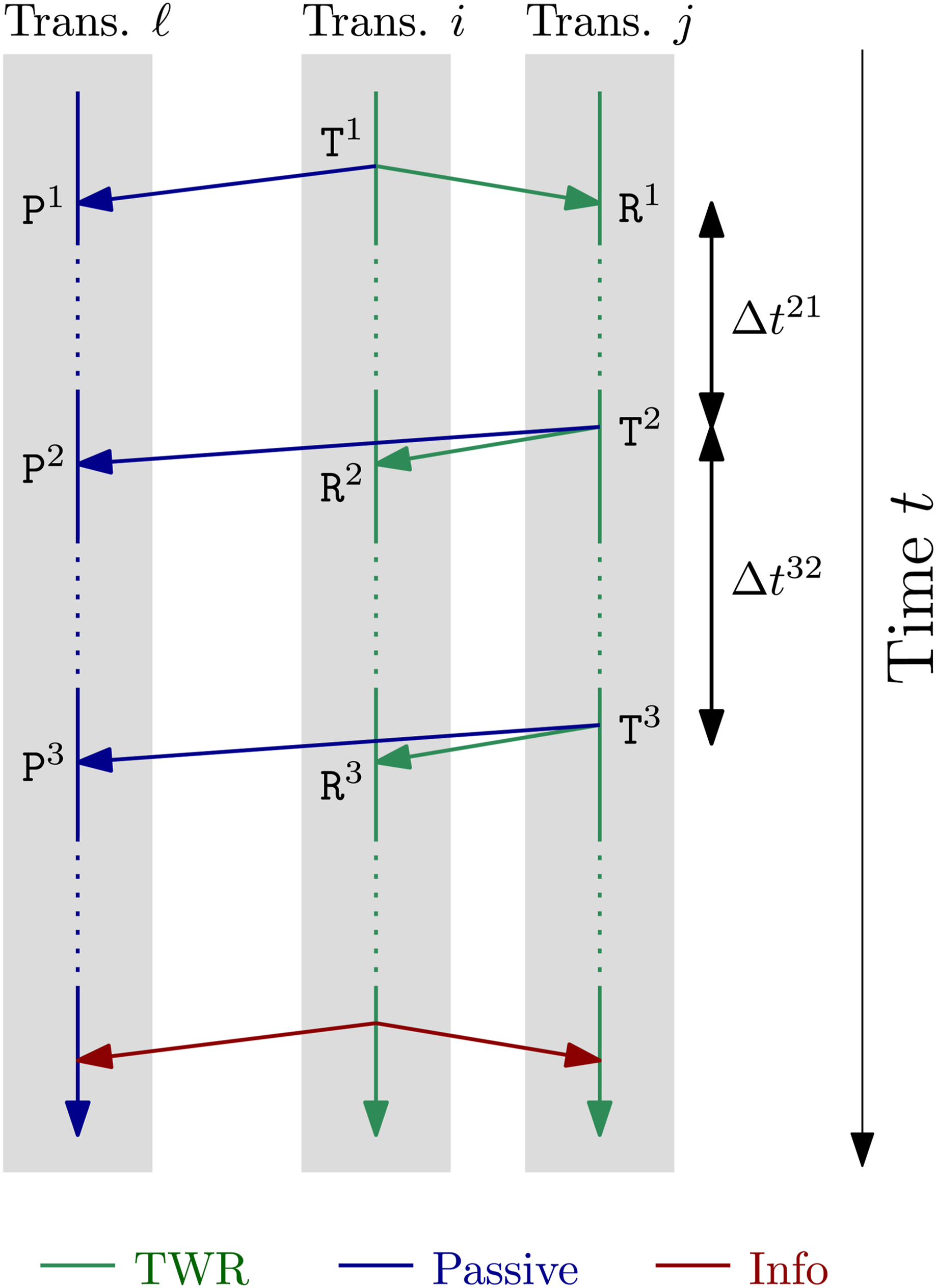
When two UWB transceivers are ranging with one another, all other transceivers are passively listening-in on the messages transmitted by the ranging transceivers as in Shalaby et al. (2024). Transceiver ℓ in Figure 7 performs this role, where it passively listens-in on all message transmissions, as shown by the blue arrows, and timestamps the kth message as
Transceivers i, j, and ℓ all need to know the DS-TWR timestamps recorded by transceivers i and j to be able to compute the range measurement (1). Transceiver j embeds the timestamps
Media-access control
The term media-access control (MAC) refers to algorithms that control when each pair of transceivers initiates a ranging transaction, while preventing other transceivers from ranging during this time window to avoid message collisions. The MAC algorithm used here involves pre-defining a sequence of unique ranging pairs, which is known to all robots. Each robot keeps track of which pair in the sequence is currently ranging by passively listening-in on neighbouring ranging transceivers, and then initiates a TWR transaction when it is its turn to do so. The sequence of ranging pairs is repeated when all pairs have successfully completed ranging transactions.
Note that the sequence of pairs does not contain ranging instances between two transceivers on the same robots, and only transceivers on robots initiate TWR transactions, as fixed transceivers, or anchors, are not connected to a computer that can command them to initiate a ranging transaction. This also means that, in the dataset, UWB data is only available as recorded by the quadcopters, and information available only at the anchors, such as passive-listening measurements recorded by the anchors, are not made available.
Message-quality metrics
In addition to the timestamps, various other metrics are recorded during UWB ranging. The CIR is a particularly rich source of information, representing the evolution of the signal recorded at a receiver from a short pulse emitted by a transmitter. Onboard the DWM1000 module is a leading-edge detection (LDE) algorithm that attempts to find the first edge in the CIR, which is then used to timestamp reception. The first peak is assumed to correspond to the signal following the direct path between the two communicating transceivers, whereas subsequent peaks may originate from reflections from objects in the environment. The output of the onboard LDE is also recorded. Both the CIR and the index of the first edge are collected using the DW1000 device API
2
(Decawave Ltd, 2016, Sections 5.59–5.60), and an example of CIR data and the LDE’s detected peak is shown in Figure 8 for one ranging transaction in the dataset. An example of a CIR reading for one ranging transaction, where the orange vertical line indicates the LDE’s computed peak.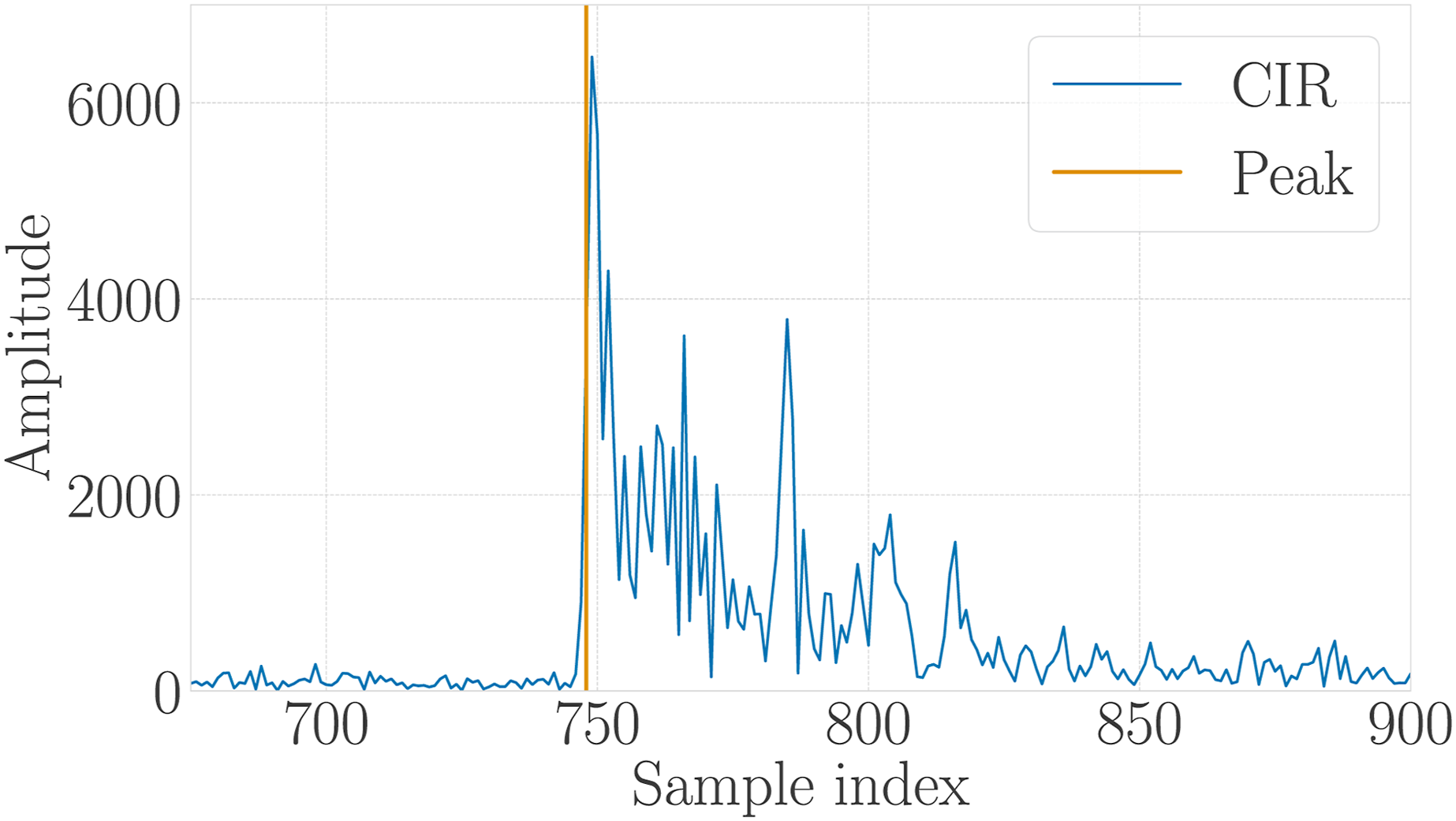
The received signal power of the ‘first-path signal’, as reported by the DWM1000 module, is also recorded. Lastly, clock-skew measurements generated using carrier-frequency offset estimation (Dotlic et al., 2018) are also recorded as part of this dataset to provide insight into the relative rates of the clocks of the different transceivers, and can be used for clock-state estimation (see, e.g., Cano et al. (2019)).
The CIR, received signal power, and skew measurements are only made available for the first and third message reception of a DS-TWR instance. This is due to the processing time required to extract these metrics that might result in the transceiver missing the last reception. Additionally, it is expected that the second and third messages share similar properties. Lastly, when the CIR is collected, the rate of ranging measurements is reduced significantly as each CIR measurement takes time to be read from the registers and transferred to the computer for storage. As such, some experiments perform ranging at a lower rate to collect CIR data, while other experiments perform ranging at a higher rate but without collecting CIR data.
Sensor calibration
Inertial measurement unit
Each quadcopter has two IMUs, one connected to the Pixhawk autopilot computer, and one embedded in the Realsense D435i camera. Each IMU consists of a 3-axis gyroscope, measuring the angular velocity, and a 3-axis accelerometer measuring the specific force, both resolved in the IMU’s own reference frame.
The IMU measurement model assumed in this dataset includes two sources of error, an additive white noise and a slowly-varying sensor bias (Barfoot, 2024, Ch. 9.4). As such, for an IMU reference frame 

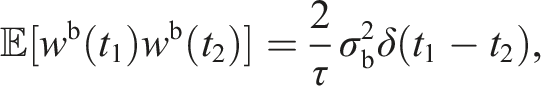
Letting w denote any of the gyroscope and accelerometer process noise components, this single-channel process noise is modelled as Gaussian white noise with 
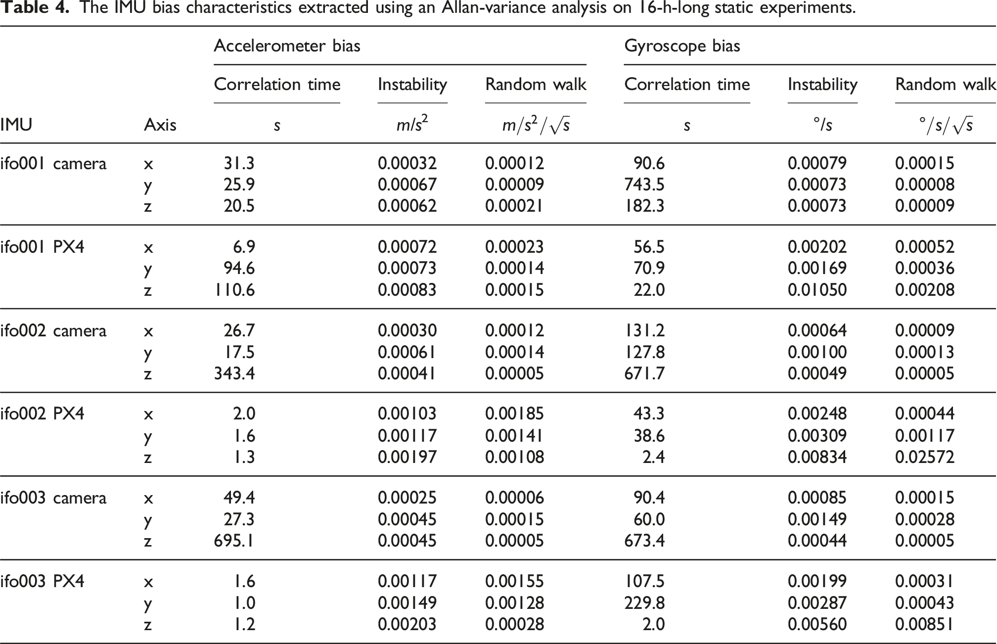
Meanwhile, letting β denote any of the gyroscope and accelerometer bias components, this single-channel bias is modelled as the combination of two terms (Pupo, 2016, Ch. 2.5): • bias instability, a high-frequency autocorrelated noise, and • random walk, a low-frequency autocorrelated noise.
Therefore, the bias process model is modelled mathematically as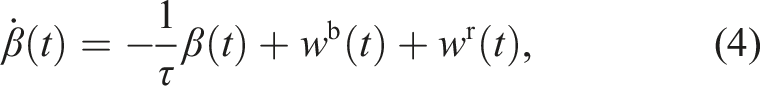

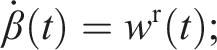
To extract σn, τ, σb, and σr, the quadcopters are placed on foam, as shown in Figure 9, connected to an external power source, and data from the IMU measurements are collected for 16 hours while the robots remain static. UWB data, although unnecessary for the IMU calibration, are also recorded. All this data is provided in the dataset in the The three quadcopters, placed on foam and connected to an external power source, during the 16-h-long static experiment to calibrate the onboard IMUs. The IMU noise characteristics extracted using an Allan-variance analysis on 16-h-long static experiments. The IMU bias characteristics extracted using an Allan-variance analysis on 16-h-long static experiments.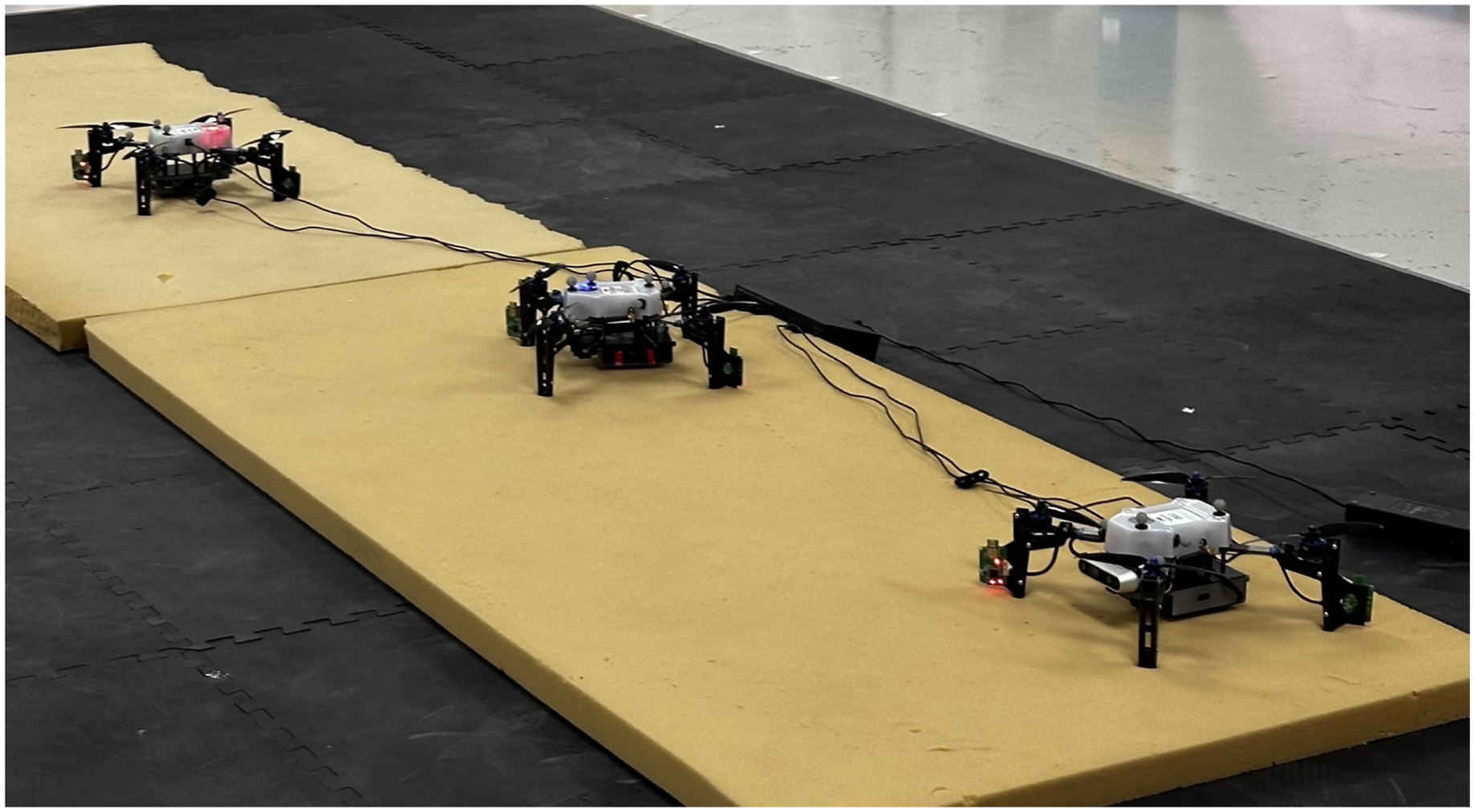
In addition, the development kit provides an estimate of the IMU biases over time for all experiments by utilizing the motion capture data. This is done by computing a ‘ground-truth’ IMU measurement from the ground-truth pose information, and then computing the difference between the recorded IMU measurements and the ground-truth IMU measurements. However, as these values would be corrupted by sensor noise, the generated IMU bias estimates are smoothed using spline fitting to reduce the effect of white noise. These smoothed IMU bias estimates are not part of the dataset but are generated using the development kit, and an example of how to access them is provided in
Camera
The Intel Realsense D435i cameras are calibrated using the
The calibration procedure is performed for one quadcopter at a time, by manually moving the robots randomly in front of a target consisting of a grid of AprilTags (Olson, 2011) in a way that attempts to excite all axes of motion, for a span of 5 min. Some images taken by one of the quadcopters during the calibration procedure are shown in Figure 10. The target used in this experiment contains six rows and six columns of AprilTags, each of size 6.25 cm × 6.25 cm and with 1.875 cm separating each AprilTag. Samples of the images recorded by ifo001 during the camera-calibration procedure.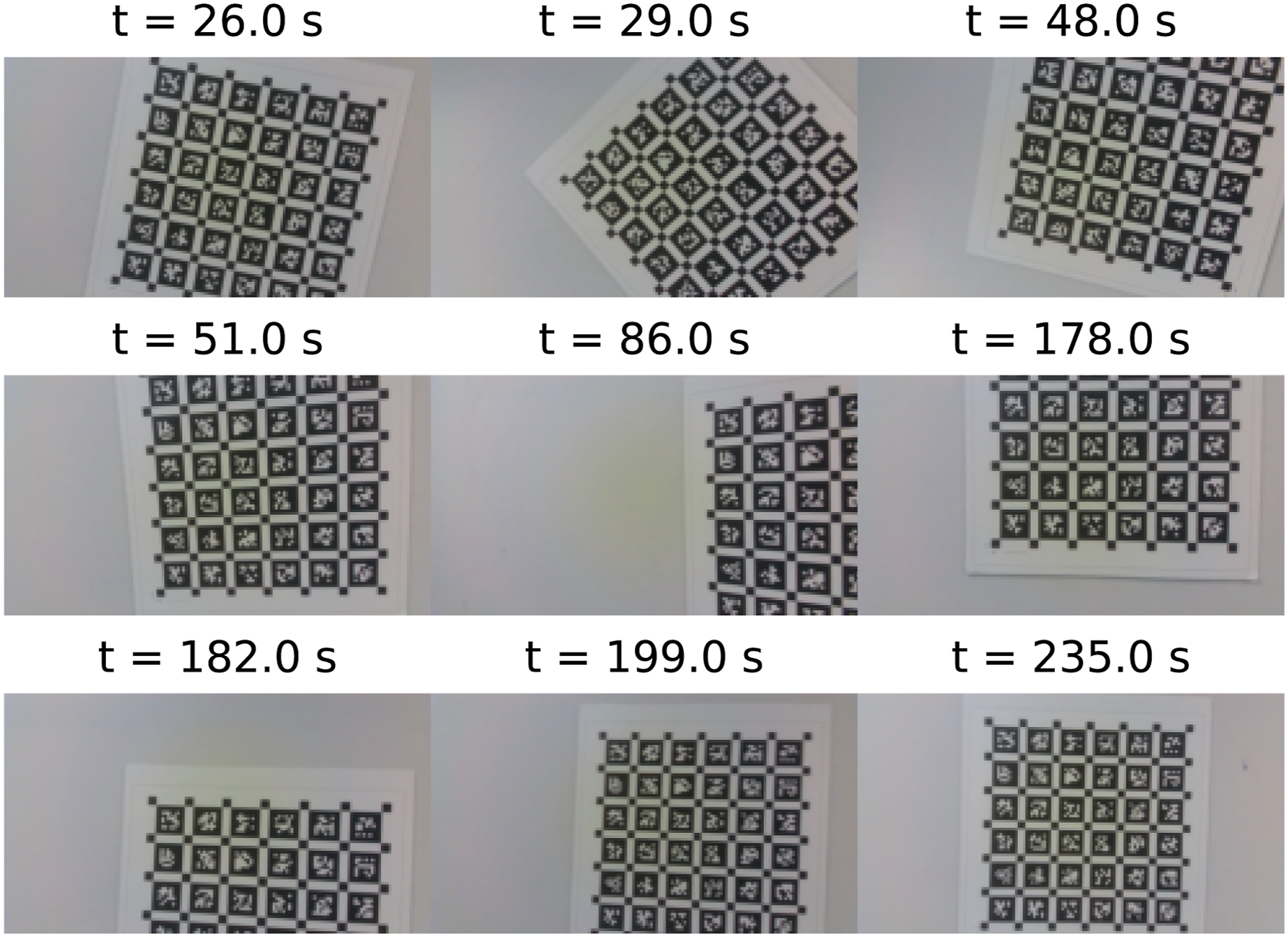
Throughout the calibration procedure, the quadcopters record the data published by each of the two cameras in the Realsense D435i, as well as the IMU measurements from both the IMU in the camera and the IMU connected to the Pixhawk computer. This allows calibrating the intrinsic parameters of each camera, such as the focal lengths, principal points, and the distortion coefficients. Additionally, the baseline between the two cameras is extracted, as well as the relative poses between the frames of both cameras and both IMUs for each quadcopter. Lastly,
Ultra-wideband transceivers
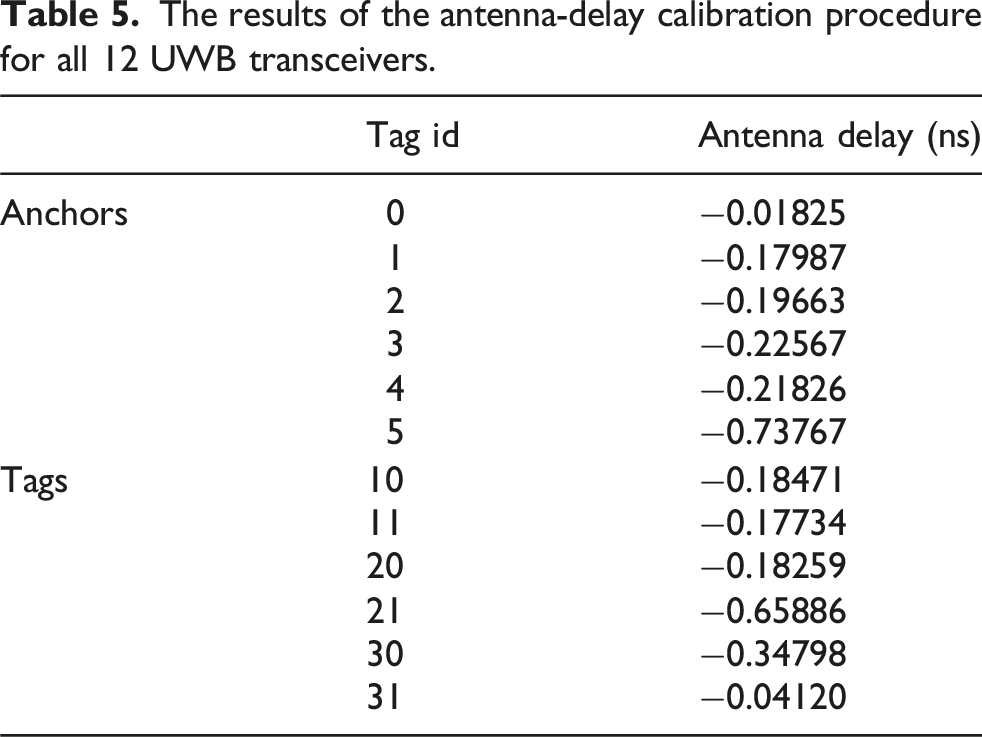
The UWB measurements are corrupted by many sources of errors, even in LOS conditions. To improve the accuracy of the UWB measurements collected, the UWB calibration procedure presented in Shalaby et al. (2023) is implemented. This involves solving for the delays in timestamping measurements at the antenna-level, and then finding a correlation between the received-signal power and the bias and standard deviation of the measurements.
This procedure involves placing the UWB transceivers on mobile robots, and collecting range measurements in as many relative poses as possible between the robots. As such, the six UWB tags are first placed on the three quadcopters, which is the default setup for the majority of the experiments in this dataset. In the absence of anchors, two 4-min-long experiments are collected with motion trajectories similar to that in Shalaby et al. (2023). Additionally, two more experiments are collected with similar motion, but with the six UWB tags replaced with the six UWB anchors instead to calibrate them as well. These experiments are available in the dataset in the
The results of the antenna-delay calibration procedure for all 12 UWB transceivers.
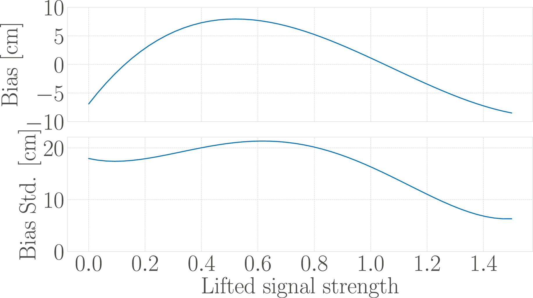
The fitted bias and standard deviation curves as a function of the lifted received signal strength, computed as per Shalaby et al. (2023).
The reported antenna delay values and the averaged power curves are used to correct the range measurements. A histogram showing the bias distribution of the calibration data is shown in Figure 12. Each experiment included in this dataset includes both raw and fully-calibrated range measurements and biases. Histogram showing the bias distribution pre- and post-calibration, using a Huber loss.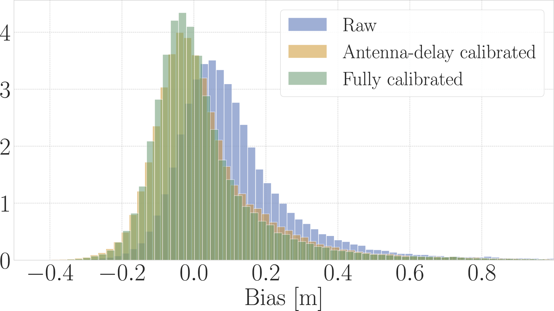
Time synchronization
Synchronization between the different computers’ clocks is important to allow the robots to timestamp measurements from the different sensors in one common clock across the entire network. At the beginning of each experiment, the clocks on the computers of all machines are manually synchronized using the Network Time Protocol (NTP), which is intended to synchronize all clocks with Coordinated Universal Time (UTC) (Mills, 2006). Specifically, the
Data collection
The collected data is broadly divided into two parts. As detailed below, one portion of the experiments includes three quadcopters, and the other includes only one of three quadcopters.
Trajectories
Three quadcopters are used to collect data for five different trajectories, which are named as follows: Random 1, Random 2, Random 3, Zigzag, and Moving Triangle. A single quadcopter is also used to collect data for eight different trajectories. These are identified as Circular 2D, Circular 3D, Random, Remote-controlled (high-paced), Remote-controlled (low-paced), Linear, Rotational, and Static. All the trajectories taken by the three quadcopters and some of the trajectories of the single quadcopter experiments are shown in Figure 13. The 10 dynamic trajectories used in the collection of this dataset.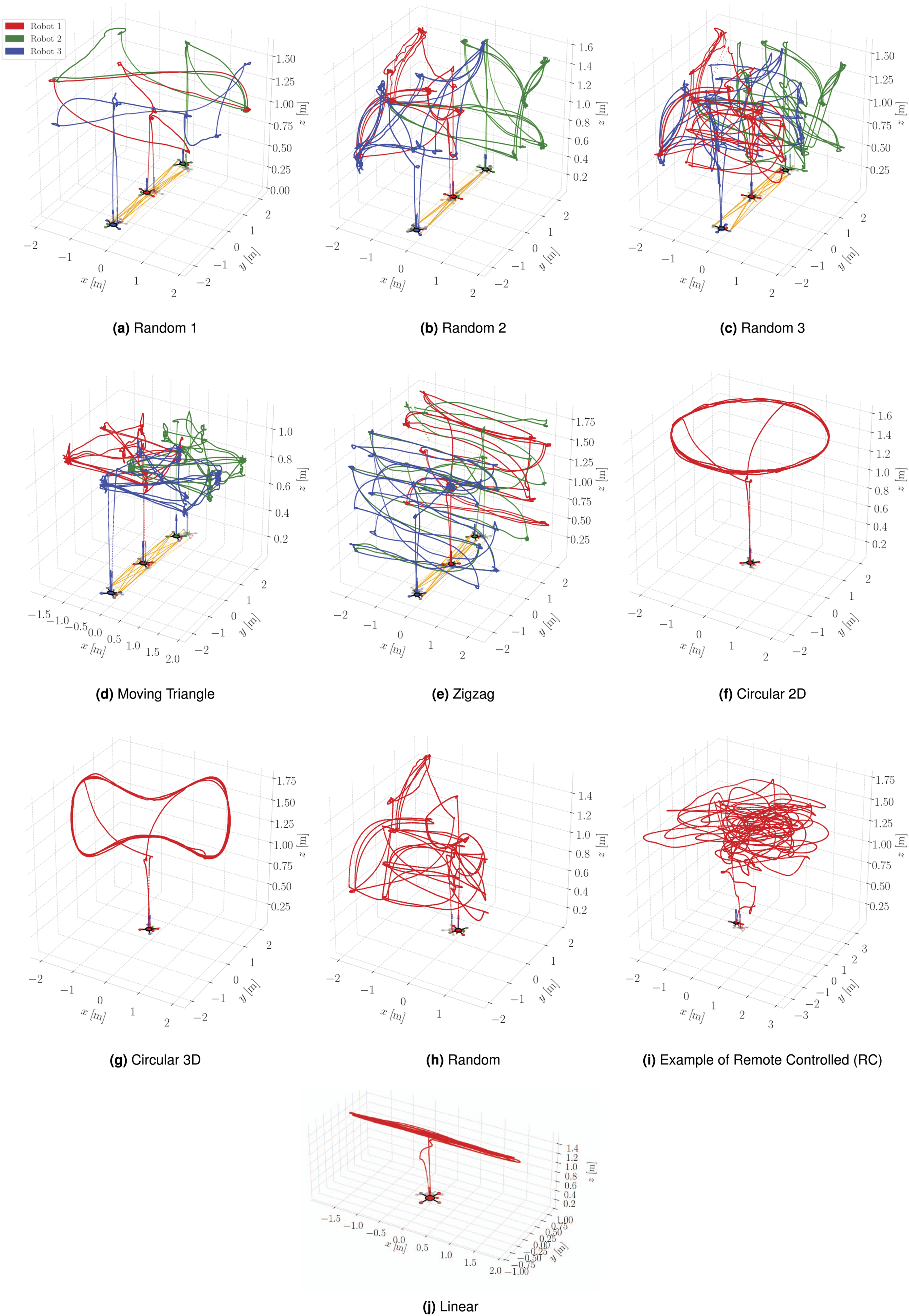
For the single-quadcopter case, the human-operated remote-controlled trajectories follow a random pattern, which is not pre-defined. There are no speed limitations on the remote-controlled high-paced trajectories and the quadcopter attained a maximum translational speed of 4.418 m/s in some experiments. For the low-paced trajectories, the quadcopter is restricted to a maximum translational speed of 0.7 m/s. Additionally, note that the Rotational and Static cases are not plotted since there is no translational movement as the quadcopter is hovering with a constant angular velocity mid-air for the former and is stationary for the latter. A combination of these trajectories and environmental setups, such as different anchor constellations, forms the basis of the experiments conducted in this work.
Experiments
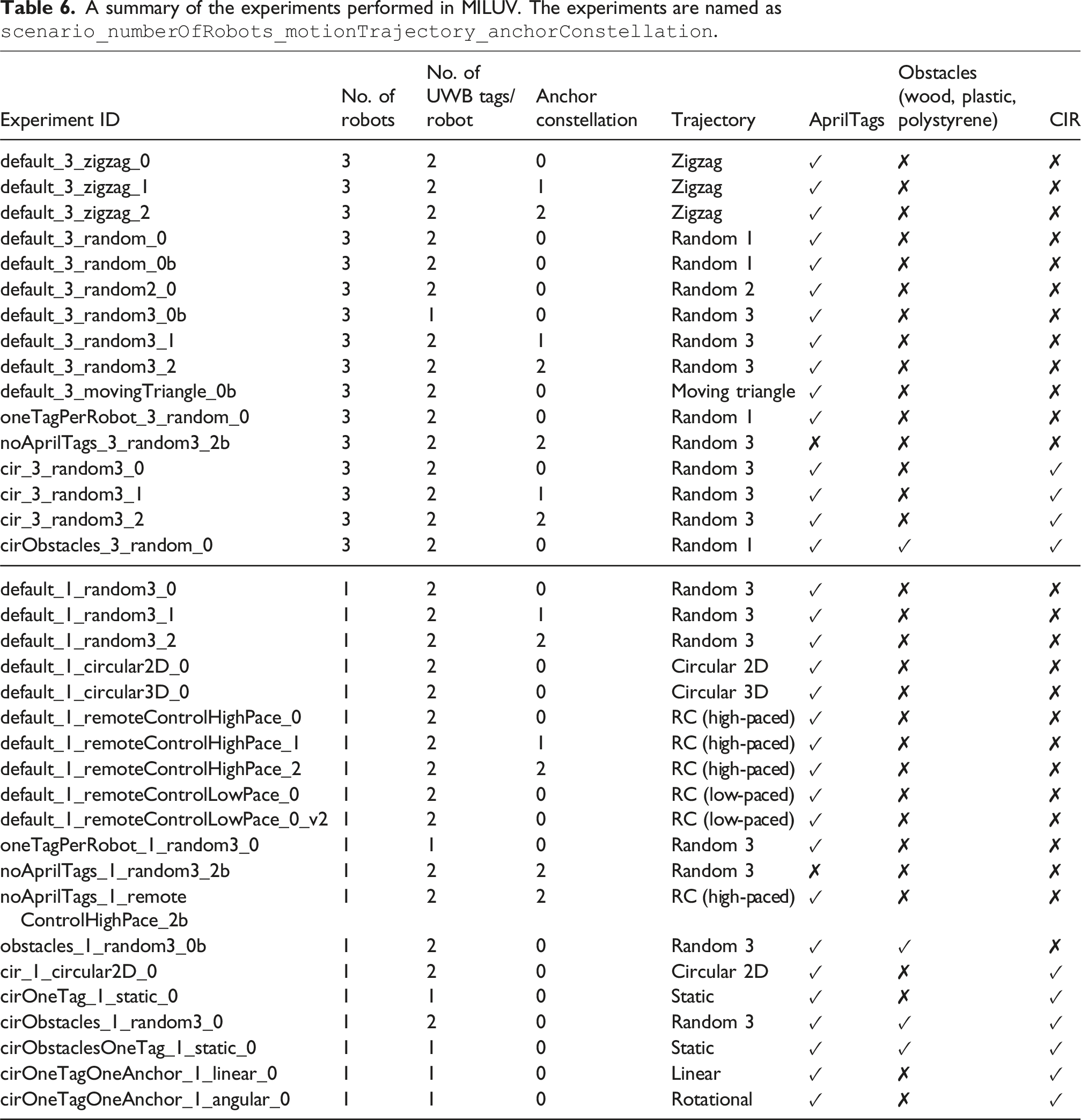
A summary of the experiments performed in MILUV. The experiments are named as
Dataset usage
Data format
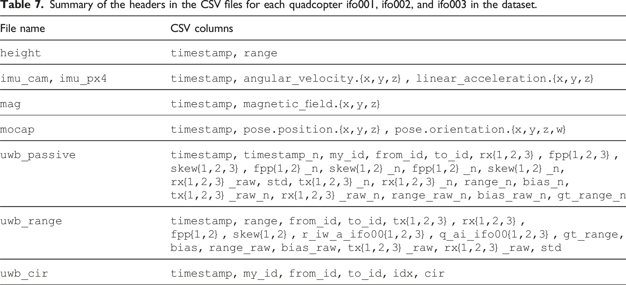
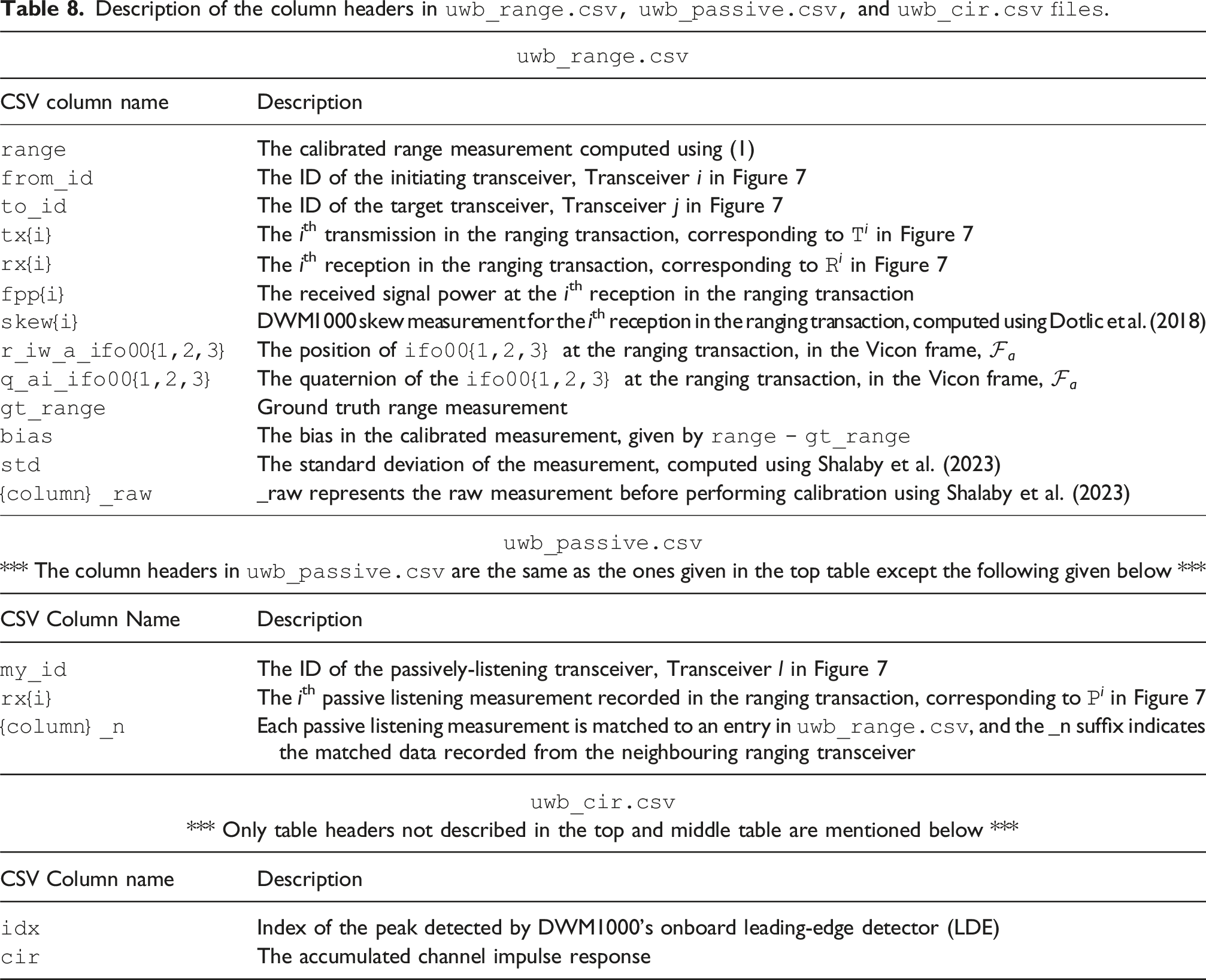
The data collected from each quadcopter’s onboard sensors is provided as a collection of File structure of the MILUV dataset. Summary of the headers in the CSV files for each quadcopter ifo001, ifo002, and ifo003 in the dataset. Description of the column headers in 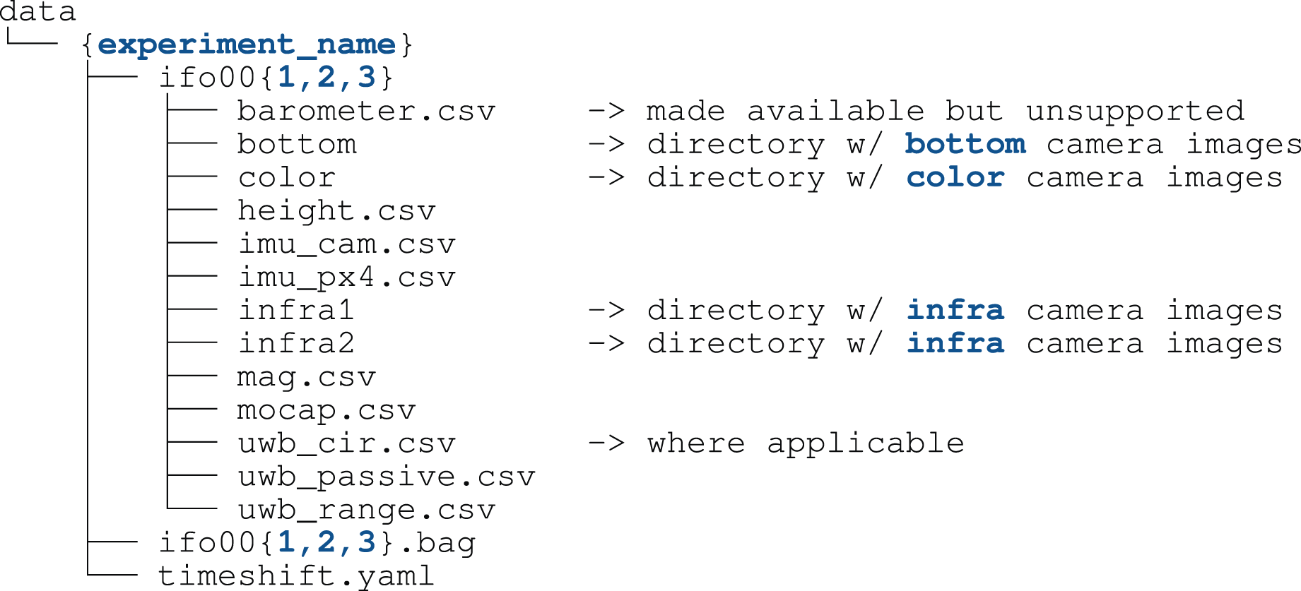
The data collected from the quadcopters’ cameras is provided as a collection of
Development kit
The MILUV development kit provided with this dataset, available at Example usage of the 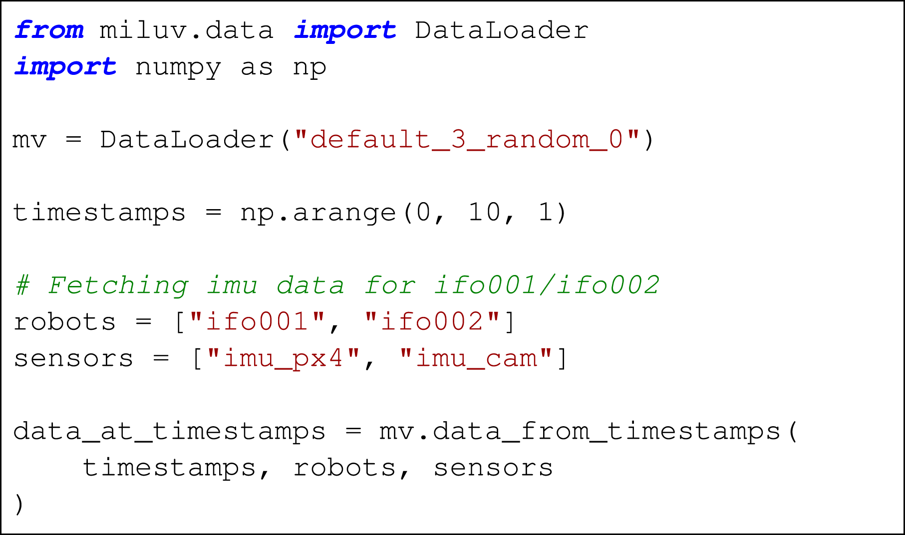
Localization benchmarking
The provided data is benchmarked using three standard localization approaches: (1) visual-inertial odometry, with and without loop-closures, (2) UWB-inertial localization using an EKF, and (3) loosely-coupled VIO and UWB corrections using an EKF.
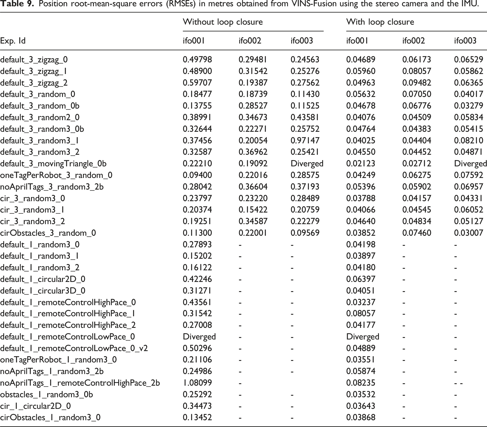
Position root-mean-square errors (RMSEs) in metres obtained from VINS-Fusion using the stereo camera and the IMU.
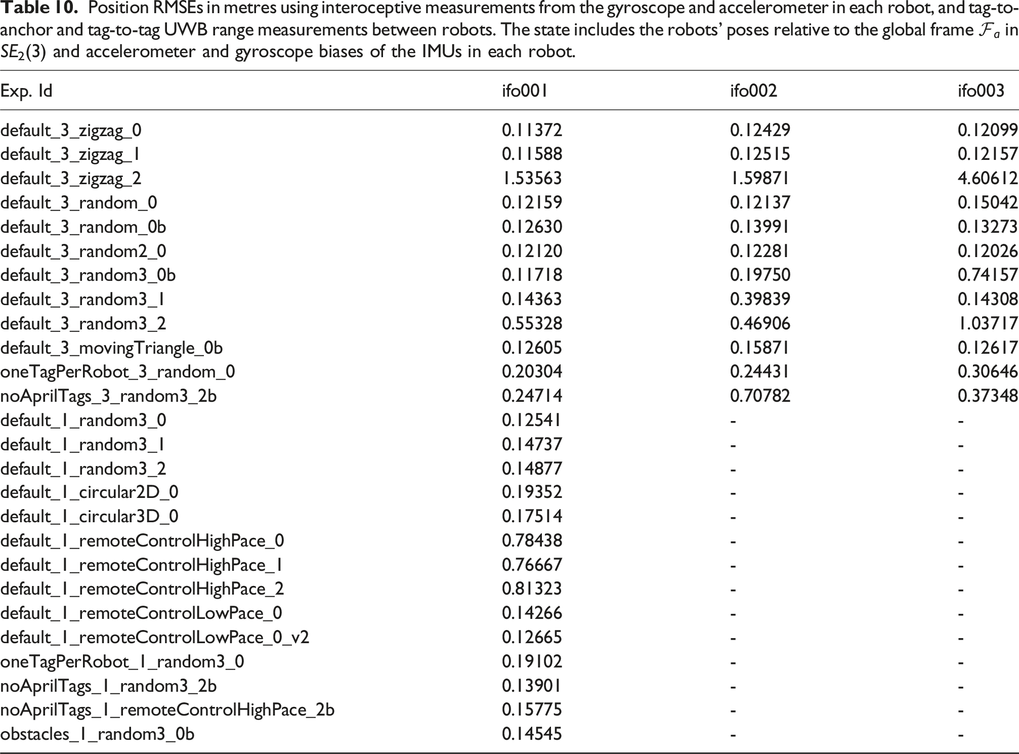
Position RMSEs in metres using interoceptive measurements from the gyroscope and accelerometer in each robot, and tag-to-anchor and tag-to-tag UWB range measurements between robots. The state includes the robots’ poses relative to the global frame
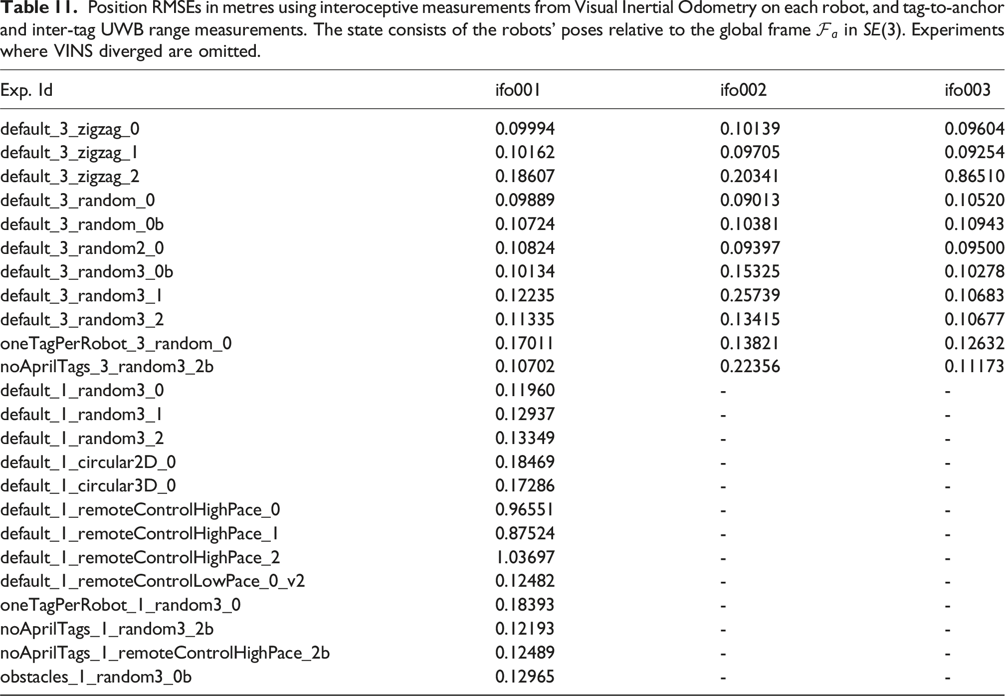
Position RMSEs in metres using interoceptive measurements from Visual Inertial Odometry on each robot, and tag-to-anchor and inter-tag UWB range measurements. The state consists of the robots’ poses relative to the global frame
Potential applications
The target application of the MILUV dataset is multi-UAV navigation with the option to fuse both UWB and visual measurements in the estimation pipeline. However, due to the variety of sensor information available, MILUV is a multipurpose dataset that can be used in applications beyond multi-robot localization.
Relative pose estimation
The problem of relative pose estimation between robots is an active area of research due to its importance in multi-robot teams. UWB and vision are particularly useful when each robot is trying to estimate where other robots are relative to themselves. When equipped with cameras, a robot can detect its neighbours and obtain direct relative pose measurements, as is done in Xu et al. (2020). Meanwhile, UWB range measurements between robots also provide information regarding the relative poses. This has been utilized in recent papers (e.g., Nguyen et al., 2018; Cossette et al., 2021; Shalaby et al., 2024) to estimate the relative poses between robots, and can be combined with vision measurements to aid in scenarios where the neighbouring robots fall outside of the camera’s field-of-view.
Visual-inertial-range SLAM
SLAM stands for simultaneous localization and mapping, and is the problem where a robot attempts to construct a map of the environment and localize itself within it. SLAM is typically done using cameras or LiDAR as they are better suited for sensing the environment, but due to the difficulties associated with SLAM stemming from the data-association problem, lighting, and the inherent unobservability, UWB has been gaining interest in the SLAM literature (e.g., Cao and Beltrame, 2021; Jung et al., 2022; Hu et al., 2024). The MILUV dataset provides all the data needed to evaluate Visual-Inertial-Range SLAM algorithms, where the UWB anchors can also be assumed to be at unknown locations to be estimated. The AprilTags provide easy-to-detect visual features, and the UWB information can be used to aid with the data-association problem or loop closures.
Moreover, multi-robot SLAM is yet another active field of research (e.g., Xie et al., 2022; Tian et al., 2023) where MILUV can be utilized. Alongside a relative position estimation algorithm, the different robots can synthetically share their mapping information for inter-robot loop closures and collaborative map building.
CIR-based localization
The CIR data incorporates a lot of information regarding the environment of a robot, and therefore can unlock a whole different approach for localization and mapping. The main challenge of inferring environmental information from the CIR is that it is hard to analytically model the behaviour of the response, as detections of reflections from different objects in the environment are superimposed, different materials reflect differently, and the measured response varies in LOS and NLOS conditions.
The accuracy of the different models trained for LOS-NLOS classification for Experiment
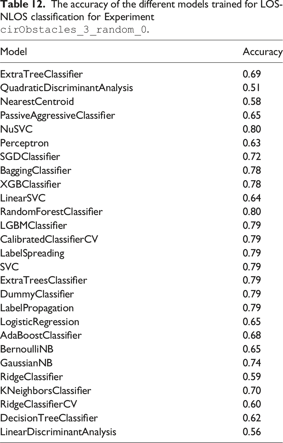
There has also been interest in the literature on CIR-based localization and mapping (Leitinger et al., 2019; Ledergerber and D’Andrea, 2020; Ninnemann et al., 2021). However, current approaches are typically limited in scope as data collection using mobile robots and CIR data is a challenging task and there are no extensive publicly-available datasets that include CIR data for multiple robots. By providing CIR data alongside data from many other sensors for multiple robots, MILUV allows the development of CIR-based solutions for resource-constrained systems in challenging environments.
Limitations and possible extensions
Before concluding this paper, it is worth mentioning some known limitations and potential areas of improvement for this dataset. The subsequent list is only accurate at the time of writing. The GitHub repository associated with MILUV will continue to be updated and maintained by the authors of this paper and hopefully the community, meaning some of the subsequent points might be addressed at the time of reading. • • – allow for a benchmark dataset with accurate Vicon-based ground-truth data, – encourage adoption of low-level UWB data in localization algorithms, and – maximize accessibility through consistency between experiments.
Nonetheless, there is value in providing experiments in more challenging settings, such as in multiple rooms and/or cluttered environments, which is a possible future direction for extending MILUV. • • •
Conclusion
This paper presents MILUV, a multi-UAV indoor localization dataset using UWB and vision measurements. MILUV is unique in that it includes multiple robots, low-level UWB data such as the raw timestamps and CIR, and vision data from a calibrated stereo camera. Three Uvify IFO-S quadcopters, each equipped with two custom-made UWB transceivers, a stereo camera, two IMUs, a magnetometer, a downward-facing camera, a barometer, and a downward-facing laser rangefinder are flown indoors. The environment includes 6 static UWB anchors, 48 AprilTags, and a Vicon motion capture system to record the true pose of the robots. The presented dataset includes many different experiments with varying combinations of number of robots, number of UWB tags, environments, and motion profiles. Calibration and obstacle data are also provided.
Alongside the provided data, a development kit is provided to facilitate the use of MILUV for the evaluation of algorithms. Various examples are provided, such as VIO and standard EKF algorithms, that provide an introduction into how the development kit can be used as well as benchmarks to be used as comparison points for novel algorithms developed by the users of this dataset. The provided development kit is made open-source, and will continue to be maintained by the authors of this paper, and hopefully by the community.
Footnotes
Acknowledgements
The authors would like to thank Saad Chidami for his assistance in the development of the custom UWB modules, as well as Steven Dahdah for his assistance with the Uvify hardware.
ORCID iDs
Funding
The authors disclosed receipt of the following financial support for the research, authorship, and/or publication of this article: This work was supported by the NSERC Discovery and Alliance Grant programs, the Canadian Foundation for Innovation (CFI) program, and the Denso Corporation.
Declaration of conflicting interests
The authors declared no potential conflicts of interest with respect to the research, authorship, and/or publication of this article.