
Abstract
The standard of care for individuals with above-knee amputation is the microprocessor-controlled knee prosthesis—a lightweight and quiet device that can actively regulate joint resistance but cannot generate positive power like biological legs during ambulation. Powered prostheses aim to address this limitation with robotic actuators. However, limitations of conventional robotic actuators result in powered prostheses that are either heavy, loud, and have high joint impedance or lack sufficient torque and power to replicate key biomechanical functions of the biological leg. These limitations have limited the clinical success of powered knee prostheses. In this paper, we show that combining quasi-direct drive with a variable transmission in a novel torque-sensitive actuator can overcome the limitations of conventional actuators in robotic knee prostheses. Theoretical analysis shows that this combination of technologies substantially extends the range of torques and speeds of an electromechanical actuator without increasing its output impedance. Mechatronics implementation of the proposed design concept into a robotic knee prosthesis confirms the torque, speed, and output impedance improvements predicted by theoretical modeling. Amputee testing verifies that the proposed knee prosthesis can provide joint torques and speeds up to 145 Nm and 550 deg/s, enabling the user to ambulate on stairs and walk at 2.5 m/s. The prosthesis achieves lower impedance than the biological knee and approximates the weight (1.9 kg) and noise (45-53 dBA) of passive microprocessor-controlled knee prostheses. By enabling lightweight, quiet, and powerful prostheses, the proposed actuation concept has the potential to improve the quality of life in individuals with above-knee amputations.
Keywords
Introduction
The current standard of care for individuals with above-knee amputation is a Microprocessor-Controlled Knee prosthesis (MPK) (Berry, 2006). MPKs regulate the physical damping at the knee joint during gait, typically by controlling one or more valves in a hydraulic circuit connected to the knee joint. In stance, when the prosthetic foot is in contact with the ground, the knee damping is set to a high value to prevent the knee joint from buckling. In swing, when the foot is off the ground, the damping is set to a minimum value, enabling the knee joint to swing freely. Due to their energetically passive nature, MPKs are generally lightweight and low noise (Genium X3, nd; Lee et al., 2020; Fu et al., 2023). However, they cannot provide net positive energy or actively control movements, limiting the ability of individuals with transfemoral amputation to perform everyday activities such as climbing stairs and ramps or standing up from a seated position.
Powered prostheses aim to address the limitations of passive prostheses by providing net positive energy and actively generating movements with their embedded electromechanical actuators. Powered knee prostheses have been shown to be beneficial in stair climbing (Ledoux et al., 2015), sit-to-stand (Hunt et al., 2023b), and stand-to sit (Hunt et al., 2023a), but have been unable to demonstrate clinical efficacy (Hafner and Askew, 2015; Kestur et al., 2024) or metabolic improvements in walking. Powered prostheses have additional drawbacks, such as high weight, impedance, and acoustic noise, which have limited their adoption (Barberi et al., 2024; Manz et al., 2022).
Available powered knee prostheses face a fundamental design tradeoff. Conventional electromechanical actuators cannot simultaneously provide optimal stance and swing performance due to the large difference in torque and speed requirements. This fundamental tradeoff negatively affects the function of powered prostheses, limiting the user’s mobility. In stance, the torque required by a knee prosthesis is generally high and the speed low (Camargo et al., 2021; Mcfadyen and Winter, 1988; Winter and Eng, 1983). Therefore, a large transmission ratio is generally desirable, as it allows the prosthesis to achieve high peak joint torque with low motor torque, reducing the heat losses in the motor windings. In contrast, in swing, the speed required by a knee prosthesis is generally high and the torque low. Thus, a low-transmission ratio is typically preferred as it allows high joint speed with low motor speed, minimizing the back electromotive force (EMF). In addition, a low-transmission ratio is desirable in swing because it reduces the inertia and viscous friction reflected from the motor and gearing to the output joint, which increases with the square of the transmission ratio. Low reflected inertia and friction are necessary to achieve ballistic swing, which is highly desirable in knee prostheses because it is efficient, biomimetic, and inherently coordinated with the user’s residual limb motion (Lee et al., 2020; Culver et al., 2022). As a result, the optimal transmission ratios for stance and swing are typically different, leading to a clear design tradeoff.
Most existing powered knee prostheses use small electric servomotors with large transmission ratios to provide sufficient torque during stance-support phases (Fagioli et al., 2024). These devices are characterized by increased reflected inertia and friction, making them unable to achieve ballistic swing (Laschowski and McPhee, 2023). Moreover, these powered prostheses weigh as much as 3-4 kg and emit up to 60-70 dBA of acoustic noise (Sup, 2009; Lawson et al., 2014; Elery et al., 2020). As a result, they are nearly twice as heavy and four times as loud as MPKs (Genium X3, nd; Fu et al., 2023), reducing their clinical and commercial viability.
Using large-diameter motors with a low-transmission ratio—a method commonly known as quasi-direct drive—has enabled the development of a powered prosthesis with low output inertia, low noise, and high torque (Elery et al., 2020). However, the authors note the inherent tradeoff between output inertia and motor mass. Due partly to the large mass of the motors and partly to the transmission design, these quieter and lower-impedance prostheses are still substantially heavier than MPKs and powered prostheses with higher transmission ratios and smaller motors (Lawson et al., 2014; Sun et al., 2018; Sup et al., 2009). Due to the negative effects of the increased prosthesis mass on the metabolic cost of walking (Browning et al., 2007; Ikeda et al., 2022), this design solution has limited clinical benefits.
Powered prostheses utilizing series elastic actuators (Azocar et al., 2020; Bhakta et al., 2018; Endo et al., 2019; Fagioli, Lanotte, et al., 2024; Fagioli, Mazzarini, et al., 2024; Pfeifer et al., 2015; Rouse et al., 2014; Sun et al., 2018) and variable stiffness actuators (Tagliabue et al., 2024) require lower peak motor power than conventional actuators under some loading conditions. Series elastic actuators also have high-fidelity closed-loop torque control, potentially allowing them to render low output impedance and achieve ballistic swing at the expense of electrical energy consumption. However, series elasticity adds weight and complexity while also reducing control bandwidth (Pratt and Williamson, 1995). Moreover, series elastic actuation does not solve the stance and swing performance tradeoffs because series elasticity does not reduce the motor’s peak torque requirements. Series elasticity also has an insignificant impact on peak motor velocity during swing-phase due to the negligible energy storage in the elastic element. Additionally, series elasticity will often increase peak motor power during stair ascent (Boudry et al., 2024), resulting in a bigger motor. Consequently, powered knee prostheses using series elastic actuators are not typically lighter, quieter, or more efficient than powered knee prostheses using conventional actuators.
Researchers have proposed relaxing the positive-power requirements of powered prostheses to achieve low weight and inertia. These semi-active and hybrid prostheses typically combine small electromechanical actuators in parallel with passive actuators, such as hydraulic systems (Andrade et al., 2018; Bartlett et al., 2022; Lee et al., 2020; Lenzi et al., 2018) or elastic systems (Rouse et al., 2014; Shepherd and Rouse, 2017; Glanzer and Adamczyk, 2018). They can also be developed using electrohydrostatic actuators (Tessari et al., 2023). In these semi-active prostheses, the electromechanical actuators provide positive power and assistance only for a subset of activities, such as during swing only (Lee et al., 2020) or during stair ascent only (Lenzi et al., 2018). Consequently, the required actuator torque and velocity are lower than in fully powered prostheses. This enables semi-active and hybrid prostheses to use smaller electric motors or a smaller transmission ratio than fully powered prostheses. Therefore, semi-powered and hybrid prostheses achieve low weight, inertia, and noise at the cost of reduced functionality, as they cannot provide sufficient torque and power to assist the users during all ambulation activities.
Variable transmissions can potentially break the torque/speed tradeoffs in powered knee prostheses. For example, switching between high and low gears at the transition between stance and swing enabled the Electronically Controlled Transmission (ECT) knee to achieve ballistic swing while still achieving moderate amounts of torque in stance (Culver et al., 2022). Similarly, a powered knee prosthesis with actively variable transmission (AVT) has shown the ability to provide high torque in stairs and low impedance in walking (Tran et al., 2019). However, the ECT and AVT knees can only switch between predefined gear ratios and only when the knee joint does not generate torque, which limits the ability of the prosthesis to adapt to changing torque/speed demands during ambulation. Torque-sensitive actuators can address the limitations of electronically controlled transmission and active variable transmission systems by continuously and passively varying the transmission ratio based on the knee torque (Tran et al., 2022). However, torque-sensitive actuators have only been implemented in actuators with high-transmission ratios, resulting in modest impedance reduction and high acoustic noise.
Despite the substantial body of work, existing powered knee prostheses can still not match the impedance, weight, and acoustic noise of an MPK while retaining sufficient torque and power to fully replicate the function of a biological leg. To address this issue, we propose combining quasi-direct drive with variable transmission in a novel torque-sensitive actuator. This paper aims to demonstrate that combining these two design strategies enables a fully powered knee prosthesis that, for the first time, does not sacrifice torque, weight, inertia, or noise in exchange for power.
Design
Design objectives and overview
Summary of prosthesis design objectives.
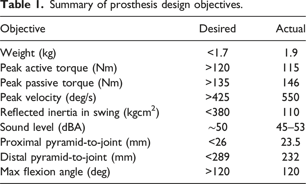
To satisfy the design objectives, the proposed knee prosthesis, namely the Direct Ball Screw Drive Knee Prosthesis (Figure 1), combines a quasi-direct drive with a variable transmission in a novel torque-sensitive actuator. The quasi-direct drive comprises a large-diameter motor and a high-lead ball screw. The proposed quasi-direct drive is integrated into a torque-sensitive actuator with a novel geometry that provides a broader range of transmission ratios than previous implementations, enabling the knee to achieve high torque and speed. The final device weighs 1.9 kg, including the batteries and covers, and has a maximum knee flexion angle of 120°. It has a peak reflected inertia of 110 kgcm2 in the low and 250 kgcm2 in the high-transmission ratio configuration. The thigh and shank segments each consist of a 7075-T6 Aluminum frame and a plastic cover, completely enclosing the mechatronics, wires, and batteries. The proximal and distal pyramid-to-joint heights are 23.5 mm and 232 mm, respectively. Direct Ball Screw Drive Knee Prosthesis overview. (a) Side profile of assembled knee. (b) Main mechanical components. (c) Main electrical components.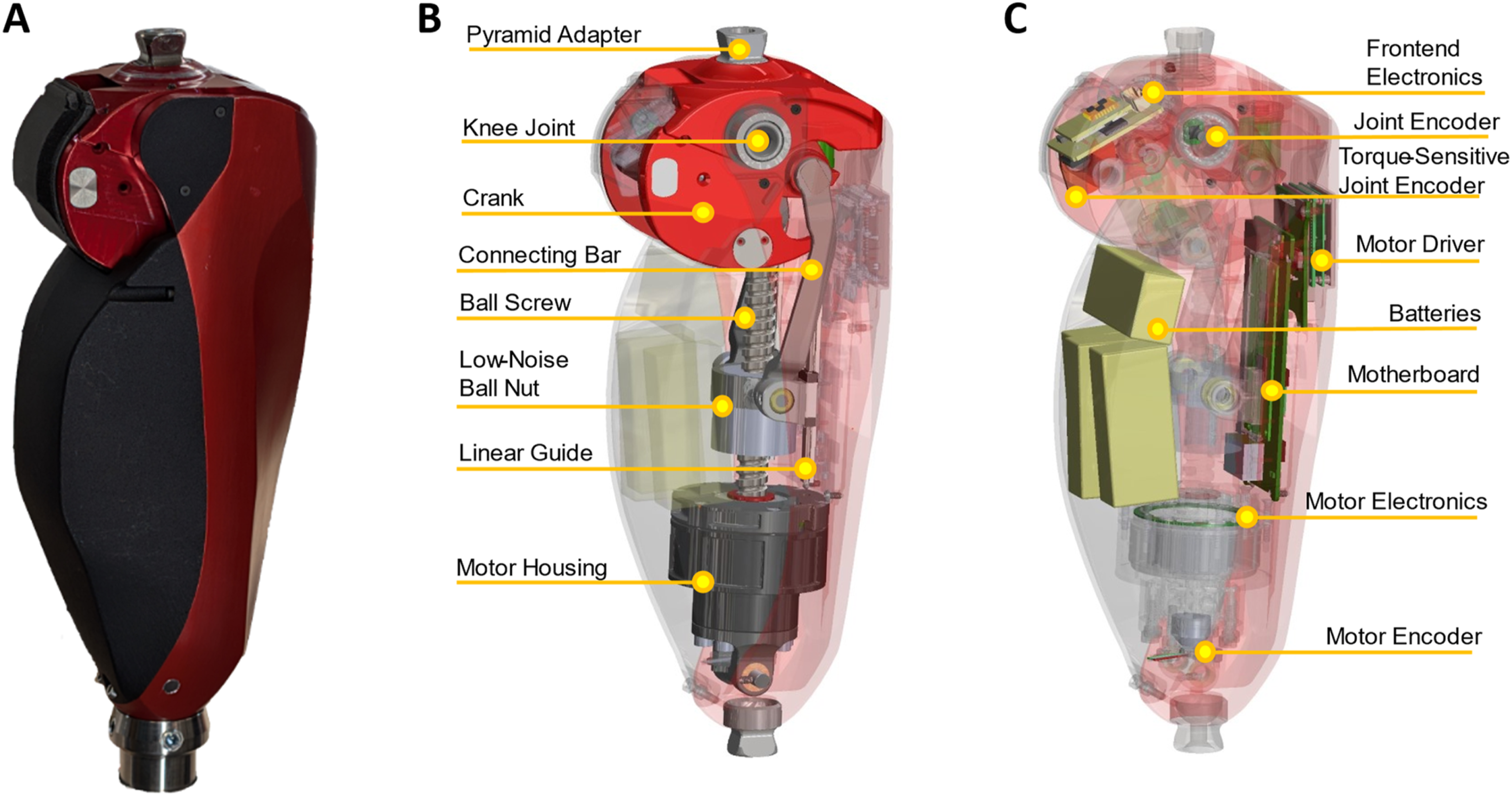
Theoretical benefits of torque-sensitive actuation
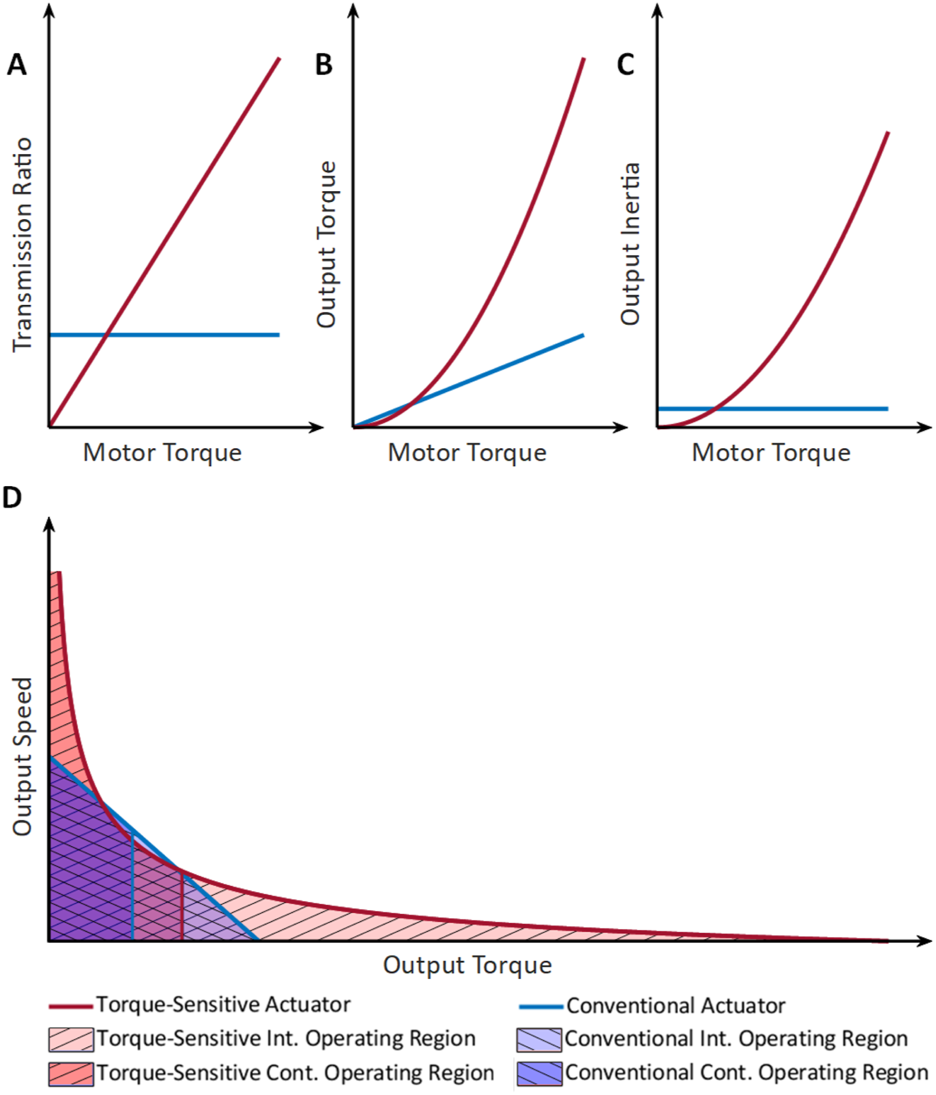
Assessing how actuator torque, speed, and inertia change as a function of the transmission ratio in geared motors demonstrates the theoretical benefits of the proposed torque-sensitive actuator. Let’s first consider a conventional actuator with a fixed transmission ratio (Figure 2(a)). For this analysis, we assume friction losses in the transmission are negligible. Using an idealized direct current motor model (Lynch et al., 2016), we find that given a nominal voltage ( Comparison of a conventional actuator with a fixed transmission ratio and a torque-sensitive actuator. (a) Transmission Ratio. (b) Output/Joint Torque. (c) Output Inertia. (d) Speed-torque curve of actuator output.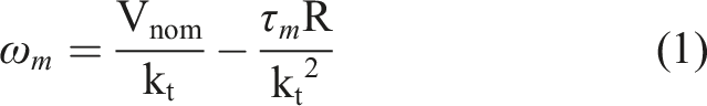
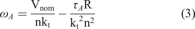
The torque-speed curve takes the form of an affine function,
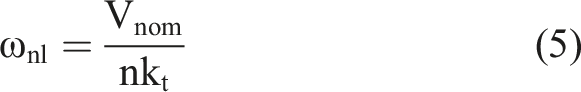
Two primary points of interest are the curve’s x-intercept and y-intercept, referred to as the stall torque (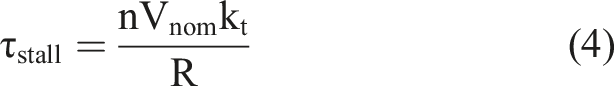
These parameters correspond to the maximum torque and speed the actuator can theoretically achieve. However, Joule heating limits the torque that the actuator can provide continuously (
The continuous operating region is the subspace of the intermittent operating region bounded by the continuous torque rating (Figure 2(d)). It contains all torque and speed combinations that the actuator can perform indefinitely without overheating. To improve actuator performance, it is desirable to increase the actuator’s range of intermittent and continuous torques and speeds; i.e., we need to increase the size of both the intermittent and continuous operating regions.
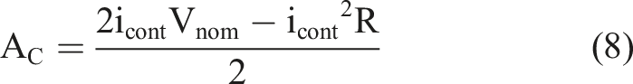
As detailed in Appendix A3, for any lossless transmission with a fixed transmission ratio, the areas of the actuator’s intermittent (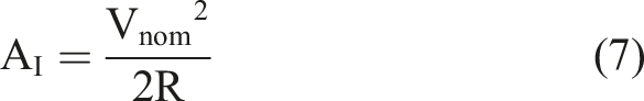
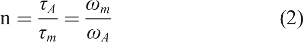
Let’s now consider an ideal torque-sensitive actuator in which the transmission ratio (

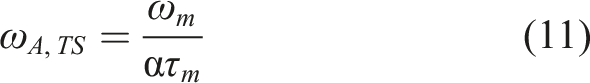
As shown in (10), the torque-sensitive actuator’s output torque increases with the square of the motor torque (Figure 2(b)). By substituting (11) into (Equation 1), we can obtain the torque-speed curve for a torque-sensitive actuator: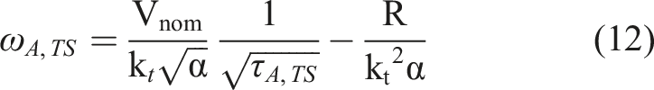
Interestingly, the torque-speed curve of a torque-sensitive actuator is not an affine function but a reciprocal square root function (Figure 2(d)).
The torque proportionality constant (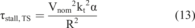
The no-load speed is effectively infinite due to the zero transmission ratio at zero torque. Thus, an ideal torque-sensitive actuator can exceed both the maximum speed and torque of a conventional actuator with fixed transmission ratio.
By integrating (12), we can calculate the area of the intermittent (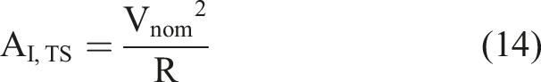

Comparing Equations (14)–(15) with Equations (7)–(8), we can see the torque-sensitive actuator has continuous and intermittent operating regions exactly twice the size of actuators with a fixed transmission ratio at the same voltage. Thus, the torque-sensitive actuator can achieve a substantially larger range of torques and speeds than a conventional actuator with a fixed transmission ratio. This behavior can enable a torque-sensitive actuator to avoid the fundamental tradeoff between speed and torque commonly seen in powered knee prostheses.
Let’s now analyze how the transmission system affects the actuator’s inertia. In conventional actuators with fixed gear ratios, the inertia of the actuator (
As shown in (16), the actuator inertia, also known as the reflected motor inertia, is constant for a fixed transmission ratio (Figure 2(c)). In contrast, by combining Equations (16) and (9), we can see that the reflected inertia for the torque-sensitive actuator (
Comparing Equations (16)–(17) shows the torque-sensitive actuator has lower inertia than a conventional actuator when the following inequality is satisfied: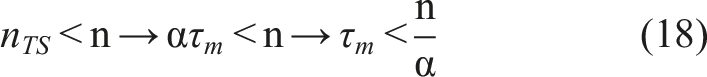
Thus, the torque-sensitive actuator has significantly lower reflected inertia than conventional actuators at low torques due to the low-transmission ratio. Because low torques are typically seen during swing in knee prostheses, the torque-sensitive actuator can achieve low reflected inertia and friction during swing, facilitating ballistic movements.
Let’s now assume that the torque sensitivity is achieved by using a spring acting between the motor and the output joint, so that the torque ratio is proportional to the spring deflection. Such a spring will affect both the torque ratio and the velocity ratio, fundamentally altering the torque-speed characteristics of the actuator. In this case, the proposed actuator acts as a torque-sensitive actuator with series stiffness. To model this system, we can start with a simple quasistatic model where the actuator’s output torque (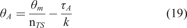
Solving (19) for motor angle (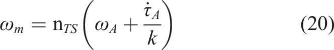
By substituting (9) into (20), we can determine the motor speed based on the output speed, torque, and torque rate: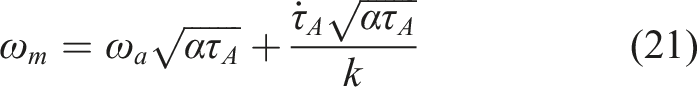
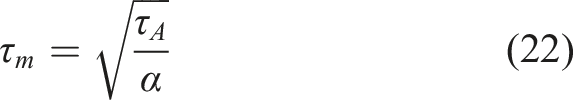
By substituting (21) and (22) into the motor torque-speed curve (1), we obtain the output torque-speed curve for our torque-sensitive actuator with series stiffness: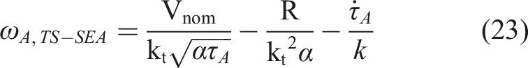
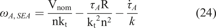
Plotting (23) and (24) yields the surfaces shown in Figure 3. Compared to the conventional series elastic actuator, the torque-sensitive actuator with series stiffness has a larger operating volume and can therefore achieve a broader combination of output speed, torque, and torque rate for the same spring stiffness. Intermittent operating region for a conventional series elastic actuator (blue) and a torque-sensitive actuator with series stiffness (red) in three dimensions.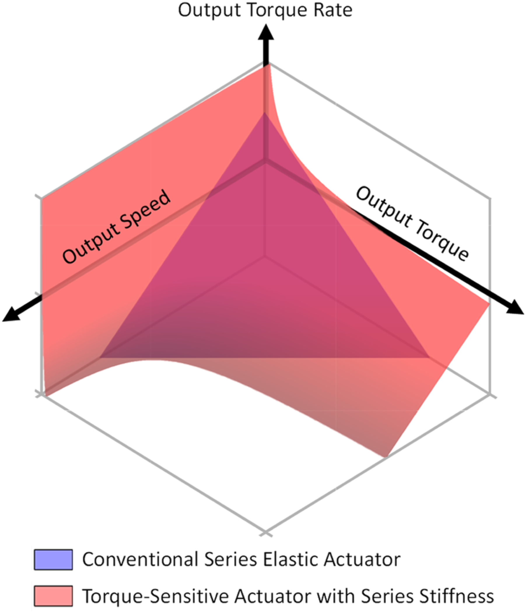
Theoretical benefits of quasi-direct drive
Quasi-direct drive systems use a large-diameter motor and a low-transmission ratio. The theoretical benefits of a quasi-direct drive can be explained by analyzing how critical motor parameters scale with the motor’s diameter and length. For constant rotor and stator thickness, electric motors exhibit the following proportionalities (Seok et al., 2012, 2015):


The transmission ratio 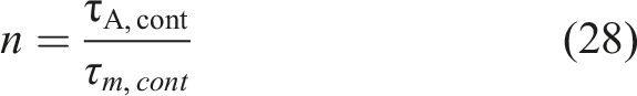
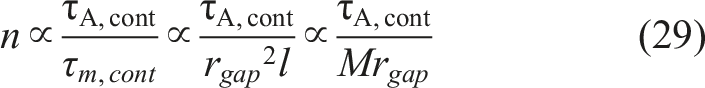
This analysis shows that using a large-diameter motor can reduce the actuator’s transmission ratio without increasing motor mass or reducing the output torque. For example, using a motor with a larger diameter but shorter length would not change the motor mass but would increase the motor torque, resulting in a lower transmission ratio.
Reducing the transmission ratio has several practical benefits. It typically produces a lighter transmission system with lower frictional losses (Seok et al., 2012, 2015). Moreover, reducing the transmission ratio results in less noise. The acoustic noise increases proportionally to the rotational speed of the transmission components (Australia et al., 2007; Zhang et al., 2018) and reducing the transmission ratio reduces rotational speed. Therefore, this analysis shows that quasi-direct drive systems can lead to quieter, more efficient, and more torque-dense powered prostheses than actuators with high-transmission ratios.
Let’s now assess how these critical motor parameters affect the output inertia. By combining (28) and (16), we obtain the inertia as a function of the actuator and motor torque: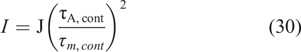
Combining (30) with (25-27) results in (31):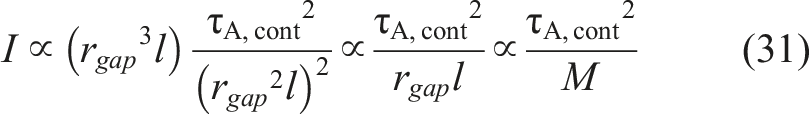
This equation shows that decreasing the reflected motor inertia requires either an increase in motor mass or a decrease in output torque, both negative outcomes for a powered prosthesis actuator. Therefore, using a large-diameter motor and a low-transmission ratio does not necessarily result in lower reflected inertia (Elery et al., 2020; Seok et al., 2012, 2015). This analysis shows that quasi-direct drive systems do not solve the fundamental tradeoff between motor mass, reflected inertia, and output torque, further motivating the need for the proposed torque-sensitive actuator.
Kinetostatic modeling of torque-sensitive actuator
The proposed torque-sensitive actuator uses a novel kinematic configuration optimized to increase dynamic performance and durability. It is a five-bar linkage that resembles an offset-slider crank with variable crank length. The crank length varies in response to variations in knee extension torque, effectively changing the transmission ratio.
Our previous implementation used a prismatic torque-sensitive joint loaded by compression springs (Tran et al., 2022) or torsional springs (Tran et al., 2023) to vary the crank length. However, due to the side loads and dry bushing implementation, the prismatic joint generated substantial friction, and the metal springs failed to pass the life-cycle testing typically required for commercial prostheses. In addition, sensitivity issues limited the actuator’s dynamic performance, decreasing the maximum modulation of transmission ratio that could be achieved (Tran et al., 2023).
The proposed new kinematic design (Figure 4(c)) addresses these problems by replacing the prismatic joint with a revolute joint loaded using polyurethane springs. Polyurethane springs (Veith Eladur) show excellent durability, high energy density, low-noise operation, and quick settling, allowing the proposed design to pass rigorous life-cycle testing. Moreover, the new kinematics achieves lower sensitivity, enabling larger transmission ratio modulation without degrading the dynamic performance (Tran et al., 2023). Torque-sensitive actuator kinematics and performance. (a) Range of motion of knee joint. Left: Fully extended position. Right: fully flexed position. (b) Range of motion of the torque-sensitive joint. Left: Low-transmission ratio position. Right: High-transmission ratio position. (c) Kinematic diagram of the torque-sensitive actuator. The linkage colors match the CAD model in B. Left: Low-transmission ratio position. Right: High-transmission ratio position. (d) Torque-sensitive mechanism in the low-transmission ratio configuration. (e) Torque-sensitive mechanism in the high-transmission ratio configuration. (f) Torque ratio as a function of knee joint angle and torque-sensitive linkage angle. (g) Reflected motor inertia as a function of knee joint angle and torque-sensitive linkage angle. (h) Maximum knee torque as a function of knee joint angle and torque-sensitive linkage angle. Gray areas in F, G, H denote areas of the surfaces that are theoretically unreachable by the torque-sensitive actuator due to torque-sensitive joint singularity.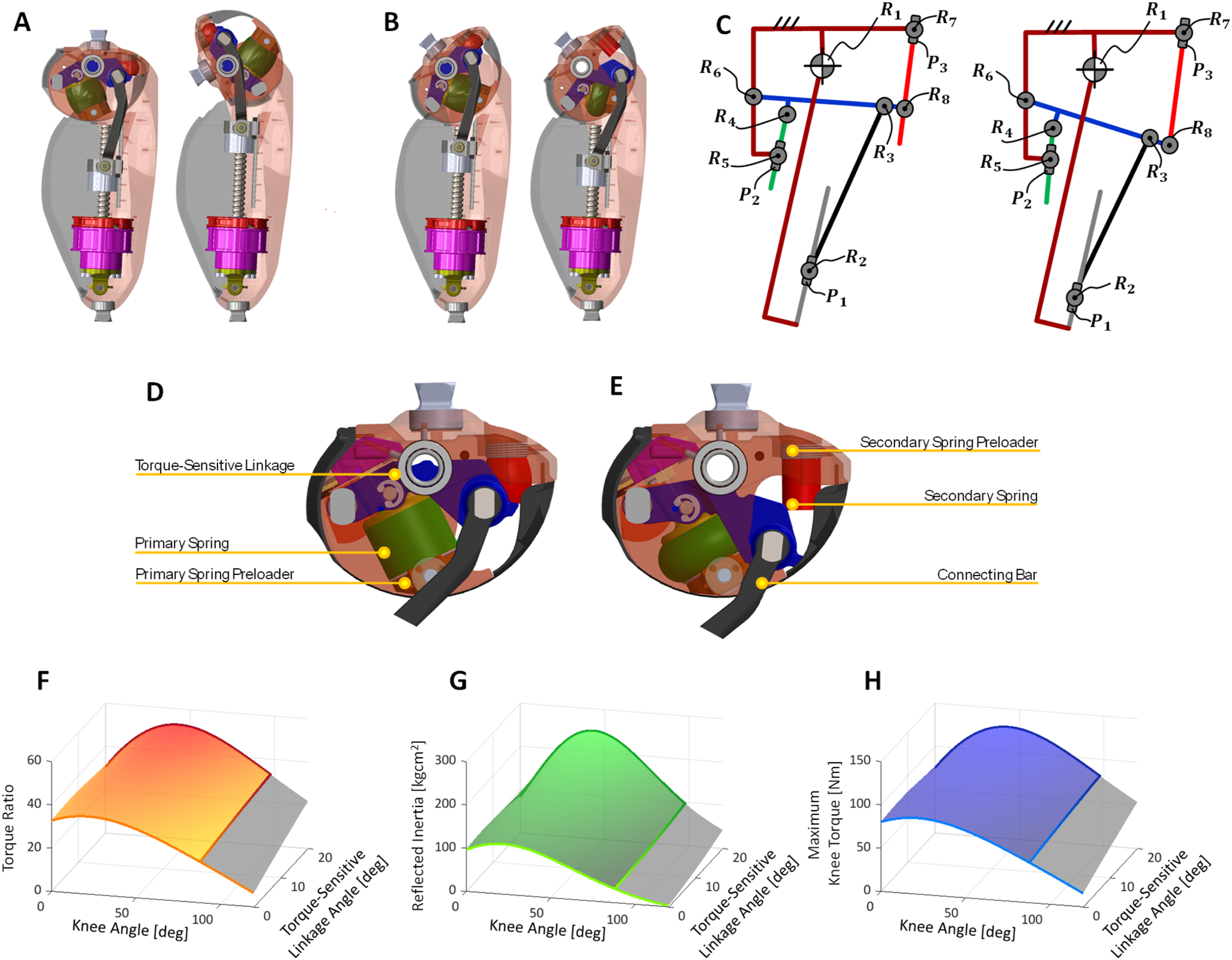
The proposed torque-sensitive actuator (Figure 4(c)) is based on a five-bar linkage with two degrees of freedom. The first degree of freedom is the angle of the knee joint. The other is the torque-sensitive joint angle, which measures the angle of the torque-sensitive linkage (Figure 4(d)) about the torque-sensitive joint (
The primary spring provides the reaction force necessary for the knee to generate a desired extension torque. Pivots on either side of the primary spring (
The secondary spring is only active during the initial range of motion of the torque-sensitive mechanism and serves two different purposes. The first function is shock absorption. The secondary spring provides a soft end-stop, reducing shock loads and acoustic noise when the torque-sensitive linkage returns to the low-transmission ratio position during unloading phases. The second function is stiffness modulation. Combined, the primary and secondary springs act as a dual-rate degressive spring system. At low knee extension torques, both the primary and secondary springs are in contact with the torque-sensitive linkage (Figure 4(d)). In this case, the two springs act in parallel, resulting in high equivalent torsional stiffness about the torque-sensitive joint (
The torque-sensitive mechanism can store potential energy in the springs. Consequently, the velocity ratio (output velocity divided by input velocity) and torque ratio (output torque divided by input torque) are not always reciprocal (Appendix A2). The torque ratio (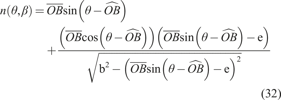
The torque ratio directly impacts the actuator’s reflected inertia. At steady-state, the reflected inertia can be defined as a function of the angle of the knee (
Figure 4(f)–(h) shows the torque ratio, reflected inertia, and maximum torque as a function of the torque-sensitive linkage angle. Notably, the relationship between the motor torque and the torque-sensitive linkage angle reaches a singularity at about 88° knee flexion. Beyond this knee angle, the motor can no longer increase the torque-sensitive linkage angle. As shown in Figure 4(f)–(h), this singularity limits the achievable torque ratio at relatively high knee flexion angles, affecting both reflected inertia and maximum output torque of the proposed knee prosthesis.
Dynamic simulation framework
We developed a dynamic simulation framework to design the geometry of the proposed torque-sensitive actuator and select components for the direct ball screw drive (Lenzi et al., 2018). The simulation framework enabled us to quickly assess how various combinations of motors, ball screws, and torque-sensitive mechanism geometries affected the knee performance. To this end, the simulation framework analyzes a combination of motor specifications, geometric parameters, and torque-speed trajectories derived from biomechanics datasets. For each combination, the framework simulates the motion of the torque-sensitive actuator, calculating the corresponding torque ratio and the resulting key performance metrics, such as the required motor current and voltage and the resulting electrical energy consumption. Moreover, it calculates the sensitivity of the torque-sensitive mechanism, which is used as a primary metric to assess the dynamic behavior of the actuator (Tran et al., 2023).
The simulations supported the actuator design in two distinct ways. First, we used brute-force optimization to analyze the design space to provide all feasible parameter combinations within certain geometrical boundaries determined by the desired device dimensions (Table 1). Then, we used a custom graphical user interface (GUI, Appendix A4) to assess feasible design solutions based on the results of the dynamic simulations. The GUI enabled us to rapidly assess how moving or altering various components impacted the device’s performance and dimensions, making informed design decisions when assessing device machinability, serviceability, durability, and weight.
Direct ball screw drive
Based on dynamics simulations, we selected a 50 mm diameter, 210 W frameless motor (TQ-Group ILM 50 × 14-DS). Frameless motors provide efficient, direct integration into the drivetrain. A custom housing (Figure 5) uses a radial bearing (McMaster-Carr 4668K276) and a dual-row angular contact bearing (Schaeffler ZKLN0624-2Z-XL) to support radial and axial loads and align the rotor with the stator. The stator is bonded to the stator housing with thermally conductive adhesive (Loctite EA 9497). The stator housing is attached to the frame through a single shaft, which adds a passive degree of freedom to reduce friction from potential manufacturing misalignments. The motor housing and prosthesis frame act as a heat sink, increasing the continuous motor current by two to three times (Azocar et al., 2020; Lenzi et al., 2018; Tran et al., 2019, 2022). The motor’s rotor is bonded to a keyed aluminum rotor adapter that drives a ball screw (KGT-12 × 5, Eichenberger). Low-noise ball screw operation is achieved through the selection of a ball nut with a relatively high lead angle and end cap recirculation (KGT-12x5-FGF, Eichenberger) (Australia et al., 2007). Thus, the ball screw is driven directly by the motor without any additional gearing or coupling. This type of drive is referred to as direct ball screw drive. Cross-sectioned CAD model of motor housing.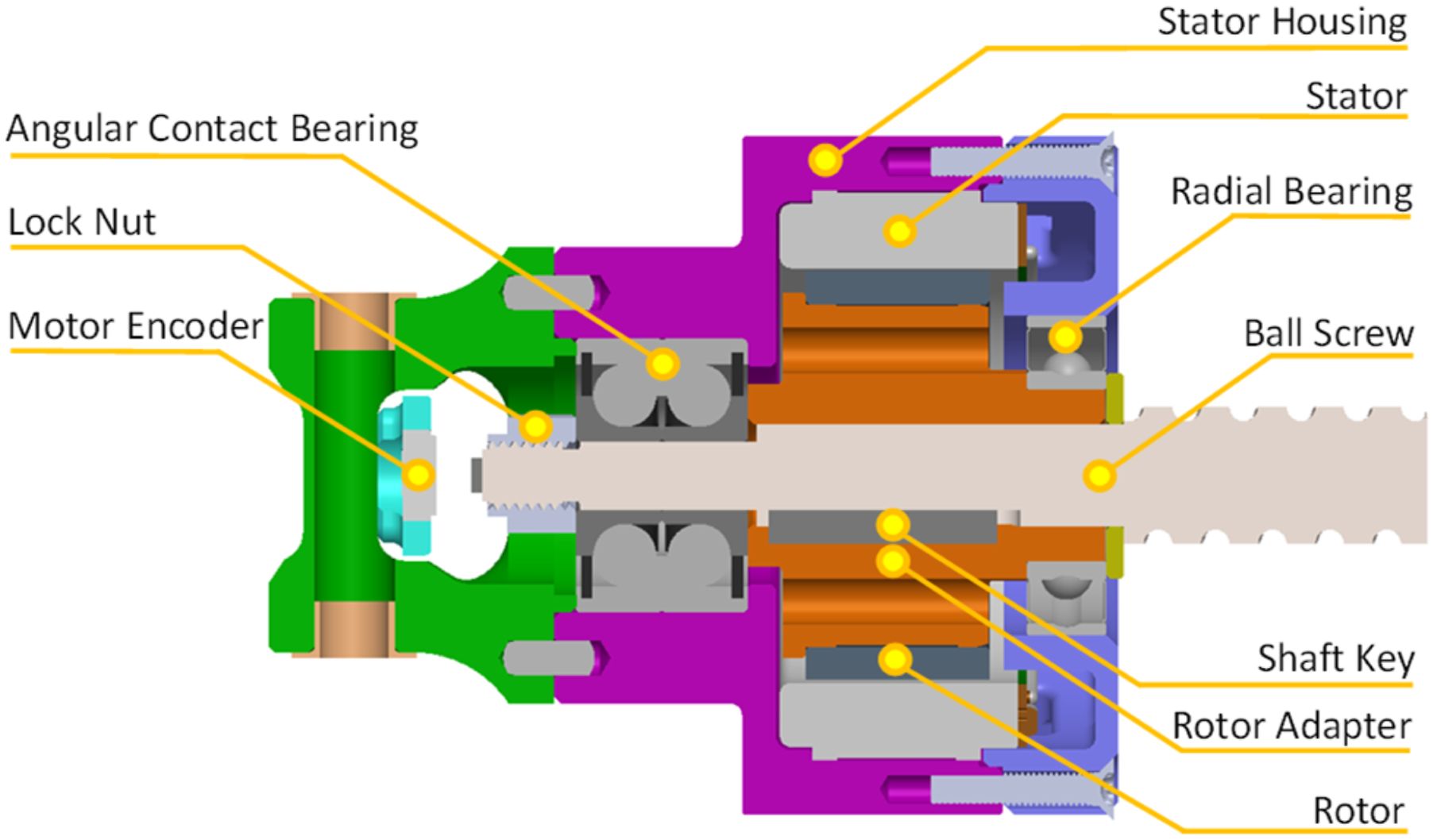
Embedded electronics and sensing
An 8-cell 1200-mAh lithium polymer battery powers the electrical system (Figure 6(g)). Custom electronic boards are housed in the thigh and shank segments of the prosthesis. The thigh segment houses the front-end electronics board (Figure 6(c)), which uses a microprocessor (PIC32MK0512MCF100) to read and process absolute encoders at the torque-sensitive joint (iC-Haus iC-MU, Figure 6(d)) and the knee joint (AMS AS5047U, Figure 6(e)) at 2.5 kHz. An inertial measurement unit (XSENS MTi-3, Figure 6(f)) reads the position of the thigh relative to the world frame at 100 Hz. The front-end electronic board communicates via SPI with the motherboard housed in the shank segment. (a) Motor servo drive breakout board. (b) Motherboard. (c) Front-end electronics board. (d) Torque-sensitive joint absolute encoder breakout board. (e) Main joint absolute encoder breakout board. (f) Inertial measurement unit breakout board. (g) Block diagram of the electronics for the knee prosthesis. Dashed lines indicate signals that are optional.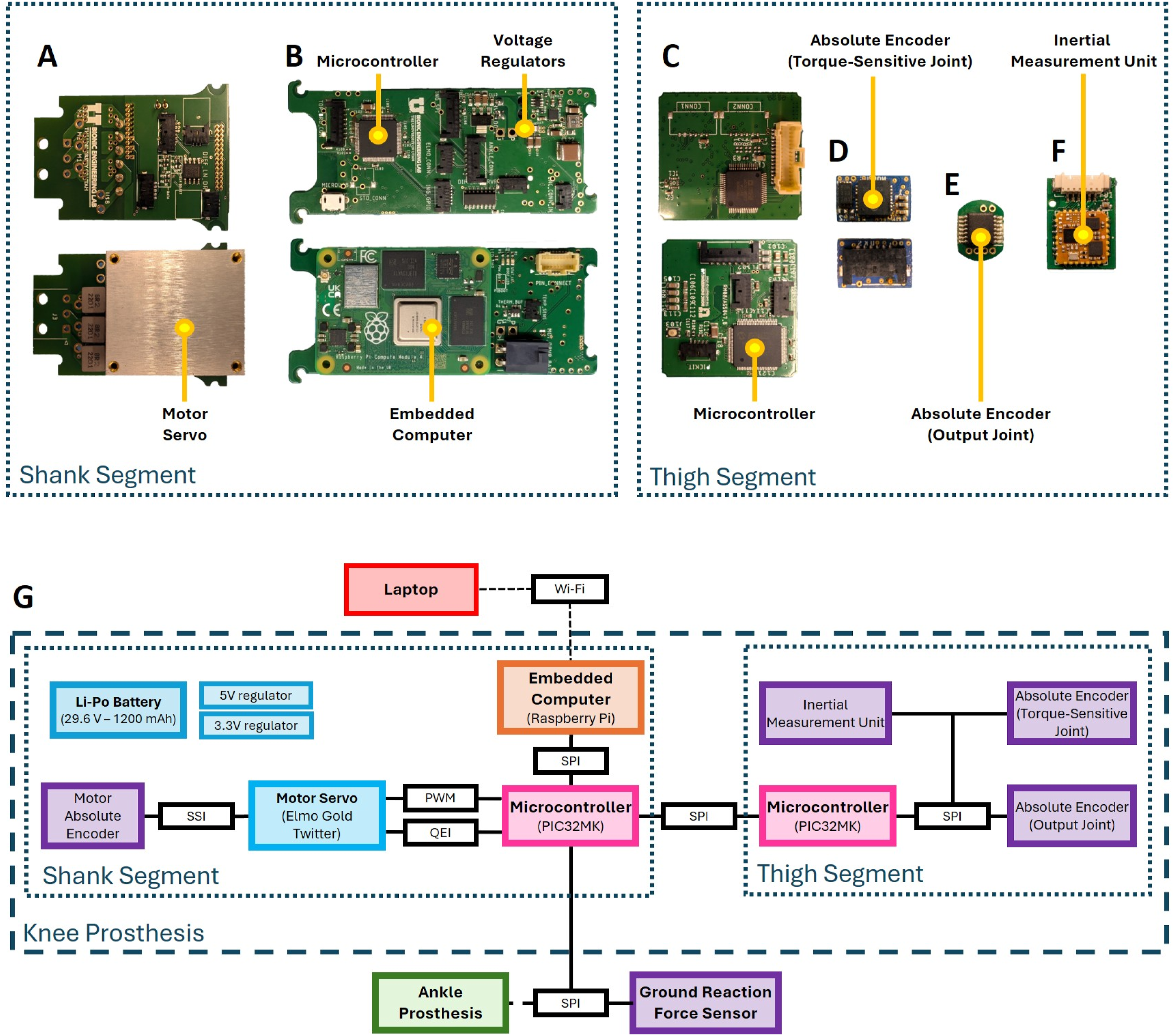
The motherboard (Figure 6(b)) uses an on-board microprocessor (PIC32MK0512MCF100) to run control routines at 2 kHz and communicate with a custom ground reaction force sensor (Gabert and Lenzi, 2019). An optional embedded computer (Raspberry Pi 3+ Compute Module) can record data and communicate with an operator’s laptop over Wi-Fi. Using a differential PWM signal, the motherboard sends current commands to the motor control board (Figure 6(a)). The motor control board houses a servo drive (Elmo Gold Twitter) running closed-loop current control on the motor. The servo drive reads the motor position using an absolute encoder (RLS RM08) for commutation. The servo drive relays the motor position to the motherboard by emulating a quadrature encoder signal.
Control
The motherboard’s on-board microcontroller runs two low-level controllers: closed-loop position control (Figure 7(a)) and joint impedance control (Figure 7(b)). The controllers command a desired torque at the joint, which feeds into an open-loop torque controller (Figure 7(c)). Both controllers have an additional feedforward torque term. The knee position ( Block diagrams for low-level control. 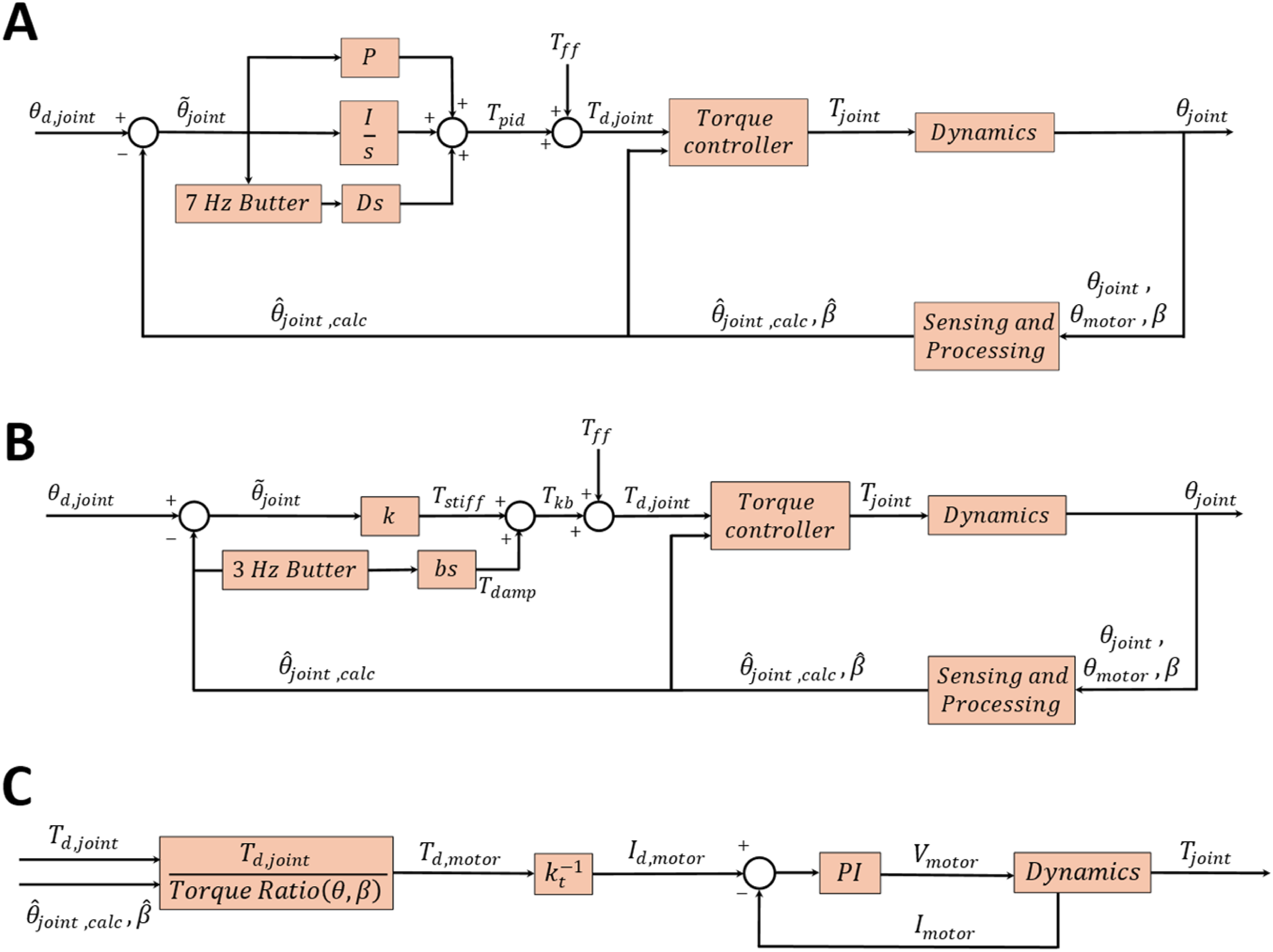
The closed-loop position controller varies the knee torque according to a PID control law to achieve a desired joint position (Figure 7(a)). The derivative of the joint position error is filtered using a first-order 7 Hz Butterworth filter. The joint impedance controller emulates a spring (
The high-level controllers used in this study were previously validated with above-knee amputees using different powered knee prostheses in combination with powered (Hood et al., 2022; Sullivan et al., 2023) or passive ankles (Cowan et al., 2023). The high-level controller automatically adapts to different activities like level and inclined walking, stair ascent and descent, and different conditions like cadence, incline, and step height without any classification or phase variables.
Validation
Benchtop testing
Backdriving experiments
We estimated the actuator’s output impedance without any software compensations by fixing the thigh segment of the prosthesis to a six-axis force-torque sensor (Sunrise Instruments M3713D) and backdriving the knee joint manually. To measure the output impedance at different input frequencies, we backdrove the system with an approximately sinusoidal trajectory, steadily increasing the frequency from 0.25 Hz to 3 Hz over 60 seconds. The resulting knee velocity and torque are plotted in the time domain (Figure 8(a)). The resulting bode plot shows the experiment data in the frequency domain (Figure 8(a)). For the tested frequency range, we estimated the impedance to vary between 0.5 and 1.5 Nms/rad. Even when backdriving the system at 3 Hz, the resulting joint torques were less than 5 Nm. Moreover, we estimated the minimum backdriving torque to be 1.1 Nm (Figure 8(b)). This torque includes both friction and cogging effects. Results of benchtop experiments. (a) Knee backdriving torque and estimated impedance when backdriven at various frequencies. (b) Knee backdriving torque when backdriven slowly. (c) Desired and measured position during closed-loop position step response. (d) Knee position during free-swing test. (e) Knee torque and motor current during open-loop torque step response. (f) Torque-sensitive linkage angle as a function of knee torque for dual-rate and single-rate spring configurations.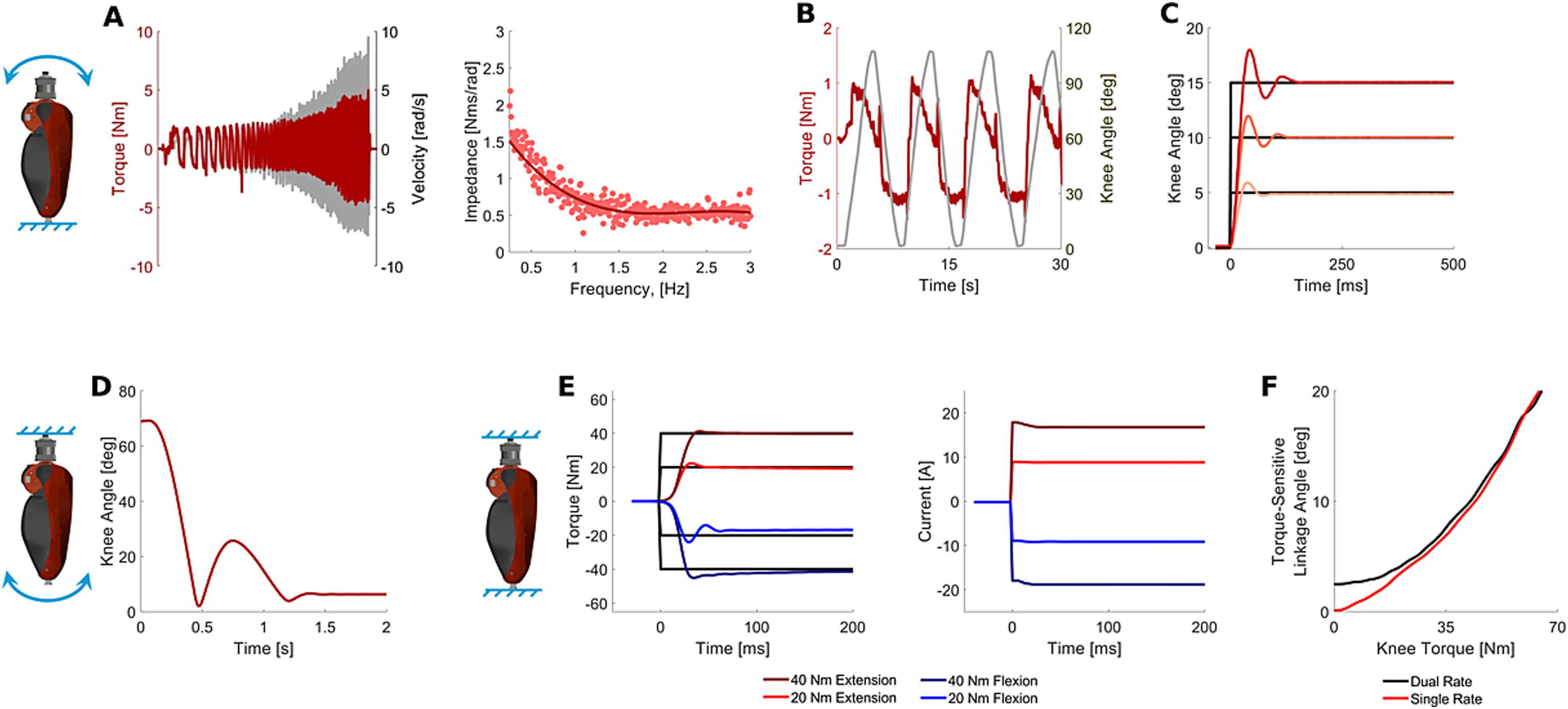
Closed-loop position step response
We performed a position step response to assess the proposed closed-loop controller’s ability to track a desired position. To this end, we commanded a step-change in the desired knee angle from 0° to 5°, 10°, and 15°. Each condition was tested five times (Figure 8(c)). The rise time across the three conditions was 19-22 ms, resulting in a -3-dB bandwidth of 16-18.5 Hz, which exceeded the bandwidth of the biological knee (Crenna et al., 2021).
Free-swing test
We tested the proposed prosthesis’s ability to generate a ballistic swing with the motors off by fixing the prosthesis thigh to the bench and attaching a passive prosthetic foot (Ottobock Taleo) to the prosthesis bottom. The knee was manually flexed and released from 70°, the peak flexion angle in the swing phase of level-ground walking. We repeated the experiment three times. The resulting mean knee trajectory is shown in Figure 8(d). The knee achieved full extension in ∼0.5 seconds, bounced back to ∼25°, and swung forward again, reaching the mechanical end stop.
Open-loop torque step response
We validated the torque-tracking capability of the proposed open-loop torque controller on the bench. With both ends of the device fixed to an aluminum frame, we commanded step torques of 20 and 40 Nm for flexion and extension and measured the knee torque with an external 6-axis force-torque sensor (Sunrise Instruments M3713D). Each condition was tested five times (Figure 8(e)).
In the extension direction, the 20 Nm and 40 Nm steps exhibited a mean rise time of 7.2 ms and 12.0 ms, respectively, and a mean overshoot of 13.5% and 2.7%, respectively. In the flexion direction, the 20 Nm and 40 Nm steps exhibited a mean rise time of 6.8 ms and 7.2 ms, respectively, and a mean overshoot of 20.0% and 11.2%, respectively. As expected, there was a slight increase in rise time when applying extension torques due to the compliance of the torque-sensitive mechanism. Across all conditions, the mean steady-state error was less than 3 Nm. The rise time across the four conditions varied from 7.2 to 13.5, resulting in a -3-dB bandwidth of 26-49 Hz. Due to the increase in torque ratio, the required current was ∼16% lower when applying extension torque than flexion torque.
Dual-rate spring characterization
To validate the degressive stiffness property of our dual-rate spring system, we commanded a triangular torque trajectory against the device’s extension end stop and measured the resulting torque-sensitive linkage angle. The experiment was performed with and without the secondary spring installed, that is, dual-rate and single-rate spring configurations (Figure 8(f)).
In the dual-rate configuration, the torque-sensitive linkage rests at its equilibrium angle of 2.5° when no load is being applied. The torque-sensitive linkage leaves contact with the secondary spring when it reaches an angle of 5° at a knee torque of 26 Nm. The torque-sensitive linkage reaches its maximum angle of 20° at a knee torque of 65 Nm. Thus, the dual-rate system has an average stiffness of 10.4 Nm/deg in the first 5° and an average stiffness of 2.6 Nm/deg in the last 15°.
In the single-rate configuration, the torque-sensitive linkage rests against the metal end-stop when no load is applied. The torque-sensitive linkage angle reaches 5° at a knee torque of 29 Nm and reaches 20° at a knee torque of 64 Nm. Thus, the single-rate system has an average stiffness of 5.8 Nm/deg in the first 5° and an average stiffness of 2.3 Nm/deg in the last 15°. Therefore, the implementation of the dual-rate system nearly doubled the initial stiffness of the mechanism without significantly changing the stiffness at higher torque-sensitive joint angles.
Human-subject testing
We recruited one individual with above-knee amputation (male, 30 years old, 72.5 kg). The participant performed a series of tests over multiple days to determine the proposed prosthesis’s ability to generate the desired torque and speed efficiently and quietly. These tests included walking on a treadmill and on level ground, ascending and descending stairs. The University of Utah Institutional Review Board approved the experimental protocol (00099066). Before participating in the study, the participant provided written informed consent. The participant also consented to the publication of photos and videos of the experiments (Figure 9). Participant wearing the Direct Ball Screw Drive Knee Prosthesis. Left: Participant ascending instrumented stairs with our powered knee prosthesis and a powered ankle prosthesis while wearing motion capture markers. Right: Participant walking on instrumented treadmill with our powered knee prosthesis and a passive ankle prosthesis.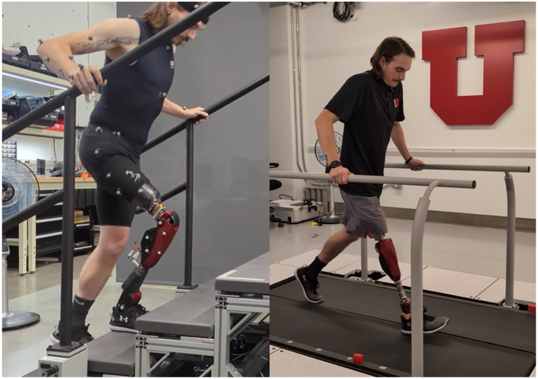
Ambulation on stairs
We tested ambulation on stairs to assess the ability of the proposed knee prosthesis to generate high knee torque during both positive (ascent) and negative (descent) power phases. For this test, the proposed powered knee was combined with a lightweight powered ankle/foot prosthesis (Gabert et al., 2021; Tran et al., 2022). The participant ascended and descended a single flight of instrumented stairs (Bertec Instrumented Stairs) with force-sensing handrails (Bertec Instrumented Handrails). A 12-camera motion capture system (Vicon Motion Systems) captured data at 200 Hz. The same motion capture setup procedure was followed as reported in (Hunt et al., 2023b) to determine the participant’s joint positions and torques.
We report the torque-sensitive joint angle, which measures the angular position of the torque-sensitive linkage (Figure 4(d)) about the torque-sensitive joint. A torque-sensitive joint angle of zero means that the prosthesis is in the low-gear position. A higher torque-sensitive joint angle correlates with a higher torque ratio.
To more easily quantify the effect of the torque-sensitive mechanism on the torque ratio, we define the torque ratio modulation (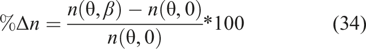
In stair ascent, the peak measured torque from the motion capture system was 115 Nm (Figure 10). The torque-sensitive joint deflected to a maximum of 17°, resulting in a 57% increase in torque ratio. The knee angle of the knee prosthesis approximately matches the able-bodied reference data (Mcfadyen and Winter, 1988). Kinematic and kinetic data from one amputee performing stair ascent and descent for one stride. Dotted lines indicate normative data from able-bodied individuals navigating stairs. Plotted torques are torques measured by motion capture.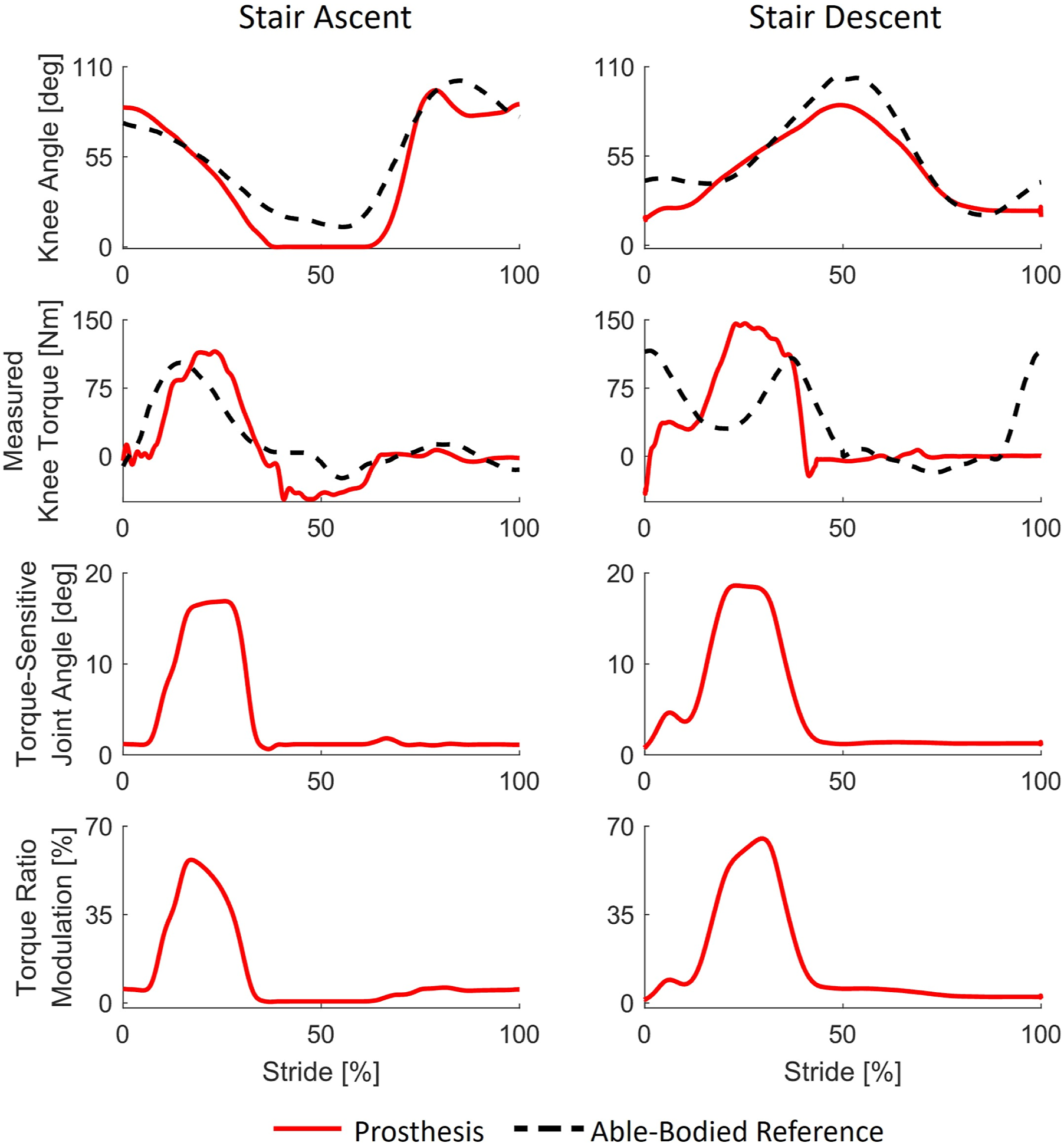
In stair descent, the peak measured torque was 146 Nm, which exceeds the weight-matched nonamputee peak torque from biomechanics datasets (116 Nm (Mcfadyen and Winter, 1988)). The torque-sensitive joint deflected to a maximum of 18.5°, resulting in a 65% increase in torque ratio.
This test shows that during stair ascent and descent, the torque-sensitive angle increased proportionally to the knee torque, resulting in a higher torque ratio in stance than swing. Moreover, it shows that the proposed prosthesis can provide sufficient torque to replicate the biomechanical function of the missing biological knee during stair ambulation.
Walking
We tested walking on a treadmill to assess the ability of the proposed prosthesis to provide sufficient torque and speed under controlled speed conditions. For these experiments, the proposed powered knee was combined with a passive prosthetic foot (Ottobock Taleo) retrofitted with a custom force/torque sensor (Cowan et al., 2023; Gabert and Lenzi, 2019b).
In the first test, the participant walked on a treadmill at 0.8, 1.0, and 1.2 m/s with the powered prosthesis tuned in standard and energy-saving modes. In standard mode, the prosthesis controller is tuned to imitate the behavior of the biological knee, including positive and negative power phases. In energy-saving mode, the prosthesis reduces its electrical consumption. In energy-saving mode, during stance, the prosthesis controller imitates the behavior of a passive MPK prosthesis using virtual damping only, so that it does not generate any positive mechanical power. We assessed electrical energy consumption in standard and energy-saving modes by measuring battery voltage and current and taking their product to determine the electrical power flowing out of the battery. Integrating battery power over each stride determines the total electrical energy consumed by the battery. When the measured battery power is negative, current is flowing into and recharging the battery, indicating electrical energy regeneration. The idle electrical energy consumption of the electronics system was subtracted before integration. The primary results of the walking tests are shown in Figure 11, including the knee angle, the knee torque, the angle of the torque-sensitive linkage, and the consumed battery power and energy. The data shown is averaged over 20 consecutive strides. Kinematic, kinetic, and electrical energy consumption data from one amputee walking in standard mode (left) and energy-saving mode (right). Dotted lines indicate normative data from able-bodied individuals walking at a normal cadence. Plotted trajectories are the average over 20 strides. Plotted torques are torques commanded to the prosthesis.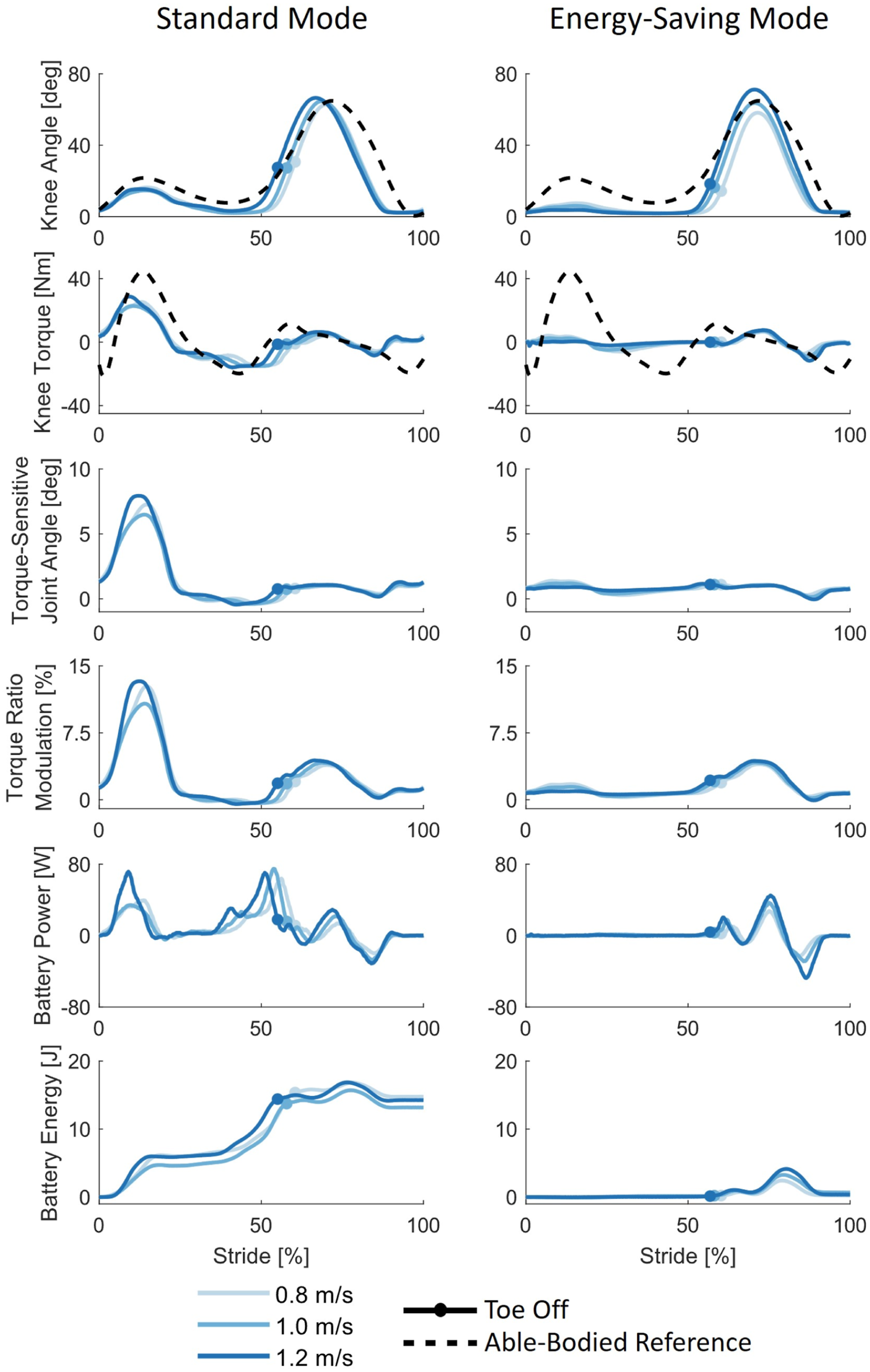
In standard mode, the prosthesis approximated the biomechanical behavior of a healthy biological knee (Winter and Eng, 1983). The peak prosthesis torque was slightly lower than the peak able-bodied reference knee torque. Specifically, the peak torque in stance was 29 Nm and 45 Nm for the prosthesis and biological knee, respectively. In swing, the highest prosthesis torque was 8.4 Nm and 6.3 Nm in flexion and extension, respectively. In contrast, the biological knee exhibits peak torques of 19.2 Nm and 11.4 Nm in the flexion and extension directions. During stance, the torque-sensitive mechanism deflected up to 8°, resulting in an 11-13% increase in torque ratio. In energy-saving mode, the prosthesis showed normative swing-phase trajectories but minimal stance-knee flexion. The peak torques in swing were 11.7 Nm in flexion and 7.5 Nm in extension, slightly higher than those observed when the participant walked in standard mode. The torque-sensitive joint showed negligible displacement, so the knee operated at the lowest torque ratio configuration throughout the gait cycle.
In all conditions, the low swing-phase torques resulted in near- or below-zero electrical energy consumption across swing phase. When ambulating in standard mode at 0.8, 1.0, and 1.2 m/s, the knee prosthesis regenerated 0.003 J, 0.46, and 0.21 J of electrical energy during swing, respectively. In energy-saving mode, the prosthesis consumed 0.04, 0.46, and 0.21 J of electrical energy during swing for the same speeds. The net electrical energy consumption per stride at 0.8, 1.0, and 1.2 m/s was 14.7, 13.2, and 14.3 J in standard mode and 0.22, 0.67, and 0.36 J in energy-saving mode, respectively. Therefore, in standard mode, an amputee could walk 17,313, 19,413, and 17,940 steps on a single battery charge. In energy-saving mode, they could walk 1,136,000, 382,260, and 707,540 steps on a single battery charge. It is important to note that these step quantities ignore the idle power consumption of the embedded electronics, which would reduce the maximum step count. Notably, the maximum number of steps in standard mode is several times greater than the number of steps an amputee takes per day (1540 (Halsne et al., 2013)). Moreover, the maximum number of steps in energy-saving mode is hundreds of times greater than that. This analysis shows that, in standard mode, the proposed prosthesis can provide nearly biomimetic knee behavior with a low electrical energy consumption across different walking speeds. Moreover, it shows that the energy-saving mode could be helpful when the battery is nearly depleted, as it would allow for many more steps so that the user can safely find an outlet to charge the prosthesis.
We assessed the participants’ maximum comfortable walking speed in a separate test. To this end, we slowly increased the treadmill’s speed until the participant felt uncomfortable walking faster. Knee position, velocity, and commanded torque to the prosthesis is shown in Figure 12. Alongside normative data taken from able-bodied individuals walking at a fast cadence (125.4 +- 4.4 steps/minute) (Winter and Eng, 1983). The data shown is averaged over 10 consecutive strides. The participant achieved a maximum walking speed of 2.5 m/s at a cadence of 148 steps/min. At this speed, the peak joint velocity of the prosthesis was 550 deg/s. During swing, the participant exhibited kinematics very similar to that of an able-bodied individual walking with a fast cadence (Winter and Eng, 1983). Despite the high joint velocities and accelerations, the prosthesis requires roughly biological torque levels to achieve a normative velocity profile. The fastest walking speed reported in prior literature is 1.6 m/s, 36% slower than the speed reported here (Elery et al., 2020; Jayaraman et al., 2018; Rezazadeh et al., 2019). This test shows that the proposed prosthesis can support walking speeds greater than the speed at which able-bodied individuals commonly transition from walking to running (Kram et al., 1996). Kinematic and kinetic data from one amputee walking at 2.5 m/s during fast walking experiment. Prosthesis data is averaged over 10 strides. Dotted lines indicate normative data from able-bodied individuals walking at a fast cadence. Plotted torques are torques commanded to the prosthesis.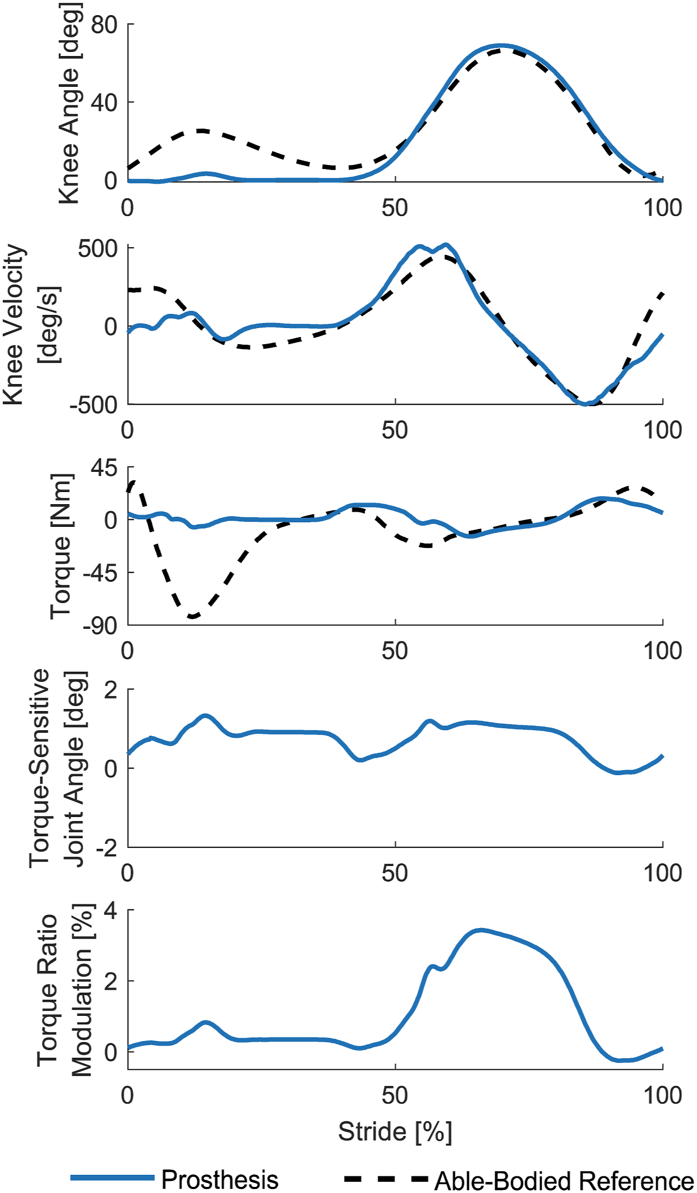
Acoustic sound levels
We performed overground walking tests to assess the acoustic noise generated by the proposed powered prosthesis while operating in standard mode. Notably, these tests could not be performed on a treadmill because the prosthesis’s noise is lower than that generated by a treadmill. We asked the participant to walk overground on a 15-m walkway at three speeds: 0.8, 1.0, and 1.2 m/s, self-paced by the participant who practiced the speeds before the tests took place.
We recorded the acoustic noise using a microphone (Beyerdynamic MM1) and amplifier (Behringer U-Phoria UMC202HD) sampling at 24 kHz. The microphone was placed 1 m from the participant’s prosthesis on their ipsilateral side and calibrated before each walking condition using a handheld sound level calibrator (Gain Express ND9B). We post-processed the audio signals using A-weighting and a fast time filter to determine the sound levels in dBA, which reflects the perceived loudness to the human ear (Mohamed et al., 2020) The participant repeated the protocol with our powered prosthesis and his prescribed passive MPK prosthesis (Ottobock Genium X3). The plotted trajectories are averaged over 10 strides for each condition Figure 13. Acoustic noise level measurements taken from one amputee walking overground with our powered prosthesis and a passive knee at three different walking speeds. Plotted trajectories are the average over 10 strides. The powered prostheses operated in standard mode for this experiment.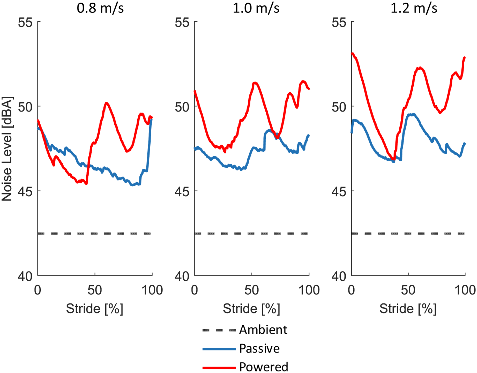
Consistently with prior literature (Fu et al., 2023), the noise level generated by the passive prosthesis was within the 46-49 dBA range, whereas that of the powered prosthesis was within 45-53 dBA. The ambient sound level was 42.5 dBA. On average, the powered prosthesis was 1.5 dBA louder than the passive prosthesis. Loudness is perceived based on a logarithmic scale where +10 dBA equals twice as loud (Mohamed et al., 2020). Thus, the powered prosthesis was only 11% louder than the passive one. This level of noise is comparable to rainfall or a refrigerator and lower than a normal conversation (R. L. C. Company, 2012).
Comparative analysis
Comparison of powered knee prostheses.
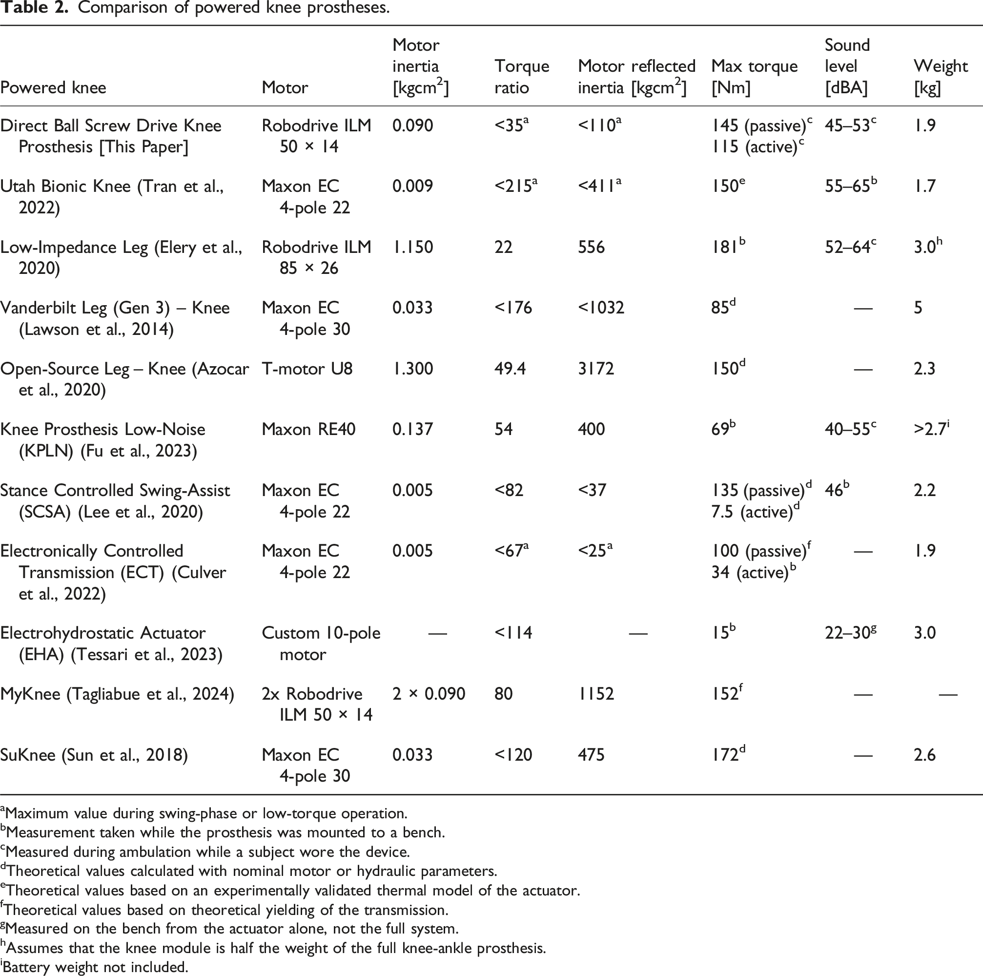
aMaximum value during swing-phase or low-torque operation.
bMeasurement taken while the prosthesis was mounted to a bench.
cMeasured during ambulation while a subject wore the device.
dTheoretical values calculated with nominal motor or hydraulic parameters.
eTheoretical values based on an experimentally validated thermal model of the actuator.
fTheoretical values based on theoretical yielding of the transmission.
gMeasured on the bench from the actuator alone, not the full system.
hAssumes that the knee module is half the weight of the full knee-ankle prosthesis.
iBattery weight not included.
Another powered knee of comparable torque and speed using quasi-direct drive actuation is the Low-Impedance Leg (Elery et al., 2020). The Low-Impedance Leg knee module is approximately 1.1 kg heavier than our prosthesis and has five times the reflected motor inertia. Due to the fixed transmission ratio, this prosthesis requires a motor (ILM 85 × 26 motor, TQ-Group) five times (∼0.53 kg) heavier than our motor to achieve ∼24% higher torque output.
It is worth noting that the proposed torque-sensitive actuator has the potential to reduce the prosthesis mass not only by reducing the motor weight but also by reducing the weight of other transmission components. The movement of the torque-sensitive joint results in an increase in the moment arm of the linear actuator, which means that for the same output torque, the linear actuator needs to provide a lower force. The reduction of force on the linear actuator enables us to select a smaller and lighter ball-screw, bearings, supporting shafts, and related frame attachments.
The only previous implementation of a torque-sensitive actuator (Tran et al., 2022) utilized a small electric motor with a high torque ratio, requiring a multi-stage transmission. This device has weight and torque capabilities similar to our powered prosthesis but almost four times the reflected inertia and twice the acoustic noise.
The ECT Knee (Culver et al., 2022) can also switch gears between stance (high) and swing (low), although only under no load. The device’s peak transmission ratio is 67 in the low gear and 359 in the high gear. During swing, the ECT Knee has 75% less reflected inertia than our powered prosthesis. However, during the stance phase, the ECT Knee can only generate one third of the active extension torque of our prosthesis and has 180% higher reflected inertia. Therefore, it cannot fully assist the user with high-torque positive-power activities such as sit-to-stand or stair ascent.
The proposed powered knee prosthesis is quieter than all other prostheses of comparable output torque (Elery et al., 2020; Tran et al., 2022) and has a similar noise level to other prostheses with substantially lower maximum torque capability (Lee et al., 2020; Fu et al., 2023).
Discussion
Limitations of available robotic actuators have prevented powered knee prostheses from achieving widespread clinical adoption. Existing powered knee prostheses cannot match the impedance, weight, and acoustic noise of passive microprocessor-controlled knees while providing sufficient torque and power to fully replicate the function of a biological leg. To address this issue, we propose a novel combination of two design solutions: quasi-direct drive and torque-sensitive actuation. Quasi-direct drive is the combination of a large motor and a relatively low-torque ratio. Torque-sensitive actuation is a type of variable transmission actuator where the torque ratio varies passively and continuously based on the joint torque. Our results show that this combination of technologies enables a powered knee prosthesis to approximate the noise, weight, and impedance of passive MPKs without sacrificing torque and power generation. The proposed device, namely the Direct Ball Screw Drive Knee Prosthesis, can provide up to 146 Nm of torque as measured by motion capture while an amputee participant wore the device. This torque level is greater than the torque capabilities advertised for commercially available powered knee prostheses (100 Nm (Intuy Knee | WillowWood, nd), 80 Nm (Ossur Power Knee, nd)). The proposed powered knee prosthesis weighs 1.9 kg, which is only 12% more than marketed passive prostheses (1.7 kg (Genium X3, nd)) and 27% less than marketed powered prostheses (2.65 kg (Ossur Power Knee, nd)). The proposed device has a maximum reflected motor inertia of 110 kgcm2 in swing, which is less than 3% of the pendulum inertia of the biological foot and shank (Honert and Zelik, 2019) and 5 to 30 times less than powered knee prostheses with comparable maximum torque (Table 2). During overground walking, the device exhibits acoustic sound levels of 45–53 dBA, which is only 11% louder than a passive MPK and quieter than a normal conversation (R. L. C. Company, 2012). The actuator’s transmission consists of common and scalable components, such as a motor and ball screw, and inexpensive, cost-effective components, such as polyurethane springs and plastic bushings. These results show that combining quasi-direct drive and torque-sensitive actuation can lead to a device that does not sacrifice weight, impedance, torque, or noise for power.
The theoretical analysis of an ideal torque-sensitive actuator shows that torque-sensitivity doubles the area of an actuator’s operating region. Increasing the area of the actuator’s operating region allows for both higher joint torque and speed. Notably, exceeding the motor’s nominal voltage can also increase the actuator’s operating region. This results in increased mechanical and thermal demands on the motor. Therefore, the amount by which a motor can be overvolted is limited. Using a larger motor can also increase the operating region due to the lower electrical resistance, but results in a larger motor mass and volume. For this reason, a quasi-direct drive actuator with a constant transmission ratio requires a much larger motor to achieve torques and speeds similar to our torque-sensitive prosthesis, increasing the prosthesis weight (Elery et al., 2020). This analysis suggests that a torque-sensitive actuator can achieve high joint torque and speed with a smaller motor than a conventional transmission.
Our torque-sensitive actuator implementation differs substantially from the idealized theoretical model. The theoretical model assumes that torque ratio is linearly correlated with input torque. With our five-bar mechanism implementation, torque ratio is nonlinearly correlated with both knee angle and input torque. This nonlinear correlation substantially affects the torque-sensitivity at large knee flexion angles, where the torque-sensitive mechanism has a singularity that prevents the torque ratio from modulating. Moreover, physical end stops limit the minimum and maximum torque ratio at a given knee angle, effectively reducing the torque-sensitive actuator’s operating region. These issues could be theoretically addressed by redesigning the torque-sensitive mechanism to avoid the singularity and changing the end stops’ locations. However, these changes may result in a larger torque-sensitive mechanism that does not satisfy the dimensional requirements for a knee prosthesis. Despite these limitations, the proposed implementation achieves more than 65% torque ratio modulation. Thus, the proposed mechatronic implementation realizes the benefits of torque-sensitive actuation, even though it does not match the idealized model.
The torque-sensitive actuator continuously and passively modulates the torque ratio based on the knee extension torque. As expected, the highest modulation (65%) was achieved in stance during stair descent when the knee provided 146 Nm of extension torque. If the actuator were locked in the low-torque ratio configuration during this experiment, the same motor current would have resulted in only 88 Nm, which is far less than the participant’s biological knee torque. In contrast, the knee remained in the low-torque ratio throughout swing-phase of all activities due to the minimal extension torques. As a result, the prosthesis achieved a knee velocity up to 550 deg/s, enabling the amputee participant to walk at a speed of 2.5 m/s. If the actuator were locked in the high-torque ratio configuration or a conventional transmission were used, the motor velocity and inertial torque would have been considerably higher, causing voltage saturation and making such high swing speeds unachievable. Thus, the combination of quasi-direct drive and torque-sensitive actuation increased the actuator’s operating region and achieved low impedance in swing, enabling the prosthesis to achieve both high torques and speeds during ambulation.
The proposed prosthesis was only slightly louder (∼11%) than the participant’s prescribed passive prosthesis. To the best of our knowledge, the measured acoustic noise level is the lowest reported for a powered prostheses of comparable torque and power (Table 2). The proposed direct ball screw drive contributed to this result by allowing for a single-stage transmission system with a relatively low overall torque ratio, reducing the number of transmission components and the components’ average rotational speed. Additionally, ball screws tend to be quieter than other gearing systems with similar transmission ratios because they use rolling contact rather than sliding contact. The proposed torque-sensitive transmission contributed to this result by adapting the transmission ratio to be particularly low in swing where high knee velocities are observed, reducing the transmission’s peak rotational speed. Thus, the proposed quasi-direct drive torque-sensitive prosthesis was much quieter than prostheses using conventional actuators (Frank Sup, 2009), quasi-direct drive alone (Elery et al., 2020), or torque-sensitive actuation alone (Tran et al., 2022). Ultimately, this result suggests that the combination of quasi-direct drive and torque-sensitive actuation achieves much quieter operation than other actuation technologies.
Our actuator exhibited very low output impedance. The minimum backdriving torque of our torque-sensitive prosthesis is only 1.1 Nm, which is similar to some of the most backdrivable prostheses in literature (Elery et al., 2020; Lawson et al., 2014; Tran et al., 2019). As shown by our theoretical analysis, torque-sensitivity reduces motor size and actuator output inertia. The output inertia of our proposed prosthesis in the low-torque ratio configuration is less than 20% of the inertia of prostheses using quasi-direct drive with a fixed transmission ratio (Elery et al., 2020) and less than 30% of prostheses using torque-sensitive actuation with a high torque ratio (Tran et al., 2022). As a result of the low output inertia, the inertial joint torques reach a maximum of only 5 Nm when backdriving the device at 3 Hz, which corresponds to a very fast cadence of 360 steps/min. Thus, the combination of quasi-direct drive and torque-sensitive actuation achieves low output impedance and small inertial torques.
The low output impedance of the torque-sensitive prosthesis facilitates ballistic swing. Knee torques during swing are dependent on the knee joint’s impedance and the shape of the imposed kinematic trajectory (Lee et al., 2020; Culver et al., 2022). During walking trials at all speeds, the knee torques required to follow a normative swing trajectory were even less than able-bodied reference torques. This result indicates that the impedance of our knee prosthesis is less than that of a human knee. Benchtop tests further show that gravity alone is enough to swing the prosthesis forward. The ballistic swing enabled the participant to walk at speeds up to 2.5 m/s. This speed is greater than the average walk-run transition speed (2.0 m/s, (Kram et al., 1996)) and 56% greater than the next-fastest walking speed previously reported with a powered prosthesis (1.6 m/s, (Elery et al., 2020; Jayaraman et al., 2018; Rezazadeh et al., 2019)). Ballistic swing is also energetically efficient, requiring little torque and primarily negative power. This characteristic is demonstrated by the electrical energy consumption experiments, which show that the proposed prosthesis consumed near or below-zero electrical energy during swing in all walking conditions. Thus, the combination of quasi-direct drive and torque-sensitive actuation allows for efficient, ballistic swing.
The proposed prosthesis achieves a unique combination of weight, torque, inertia, and noise. It is substantially lighter and has lower output impedance during walking compared to quasi-direct drive prostheses with a fixed transmission ratio. Compared to devices using torque-sensitive actuation paired with highly geared motors, it is substantially quieter and has lower output impedance, although it is slightly heavier. In summary, the proposed prosthesis demonstrates that the combination of torque-sensitive actuation and direct ball screw drive effectively addresses the limitations previously highlighted in the comparative analysis.
Theoretical analysis shows that quasi-direct drive systems are generally more torque-dense than actuators with high-transmission ratios (Elery et al., 2020; Seok et al., 2012, 2015). However, our quasi-direct drive torque-sensitive actuator is not lighter than our previous implementation of a torque-sensitive actuator, which has a higher overall torque ratio (Tran et al., 2022). This lack of weight reduction is primarily due to implementation. Specifically, we modified the torque-sensitive mechanism to increase durability and achieve three million loading cycles on a testing machine. This modification required new rotational joints with heavier shafts. Additionally, we reduced the torque-sensitive mechanism’s sensitivity (Tran et al., 2023), which required a stiffer and larger spring, resulting in larger shafts, frames, and preload mechanisms.
Human-subject experiments demonstrated that the proposed torque-sensitive prosthesis can be used in combination with both powered and passive ankle-foot prostheses. During stair negotiation, the proposed knee prosthesis was combined with a lightweight powered ankle prosthesis (Gabert et al., 2021) to achieve sufficient dorsiflexion, placing the user in a more advantageous position to receive high magnitudes of knee torque. However, the powered ankle-foot prosthesis introduces a confounding factor when measuring the electrical energy consumption and acoustic noise of the powered knee prosthesis. For this reason, a passive ankle-foot was used in all walking experiments.
The implementation of torque-sensitive actuation through our kinematic configuration has some intrinsic limitations. The torque ratio modulation decreases as the knee flexes, reaching a singularity at 88°degrees. This knee-angle dependency creates a tradeoff between torque ratio modulation and dynamic behavior. Using a more compliant spring would increase torque ratio modulation at high knee angles. However, it would also result in lower torque-control bandwidth and higher motor velocities during some ambulation activities, similar to series-elastic actuators (Pratt and Williamson, 1995). These high motor velocities may result in voltage saturation or poor dynamic behavior. The proposed degressive spring mechanism partly addresses this tradeoff by stiffening only the beginning of the torque-sensitive joint motion, where high accelerations occur. However, it does not resolve the tradeoff completely. Simulations indicate that the singularity can possibly be avoided by changing the geometry of the torque-sensitive mechanism. However, this strategy is likely to result in a larger mechanism or a decrease in maximum torque ratio modulation. Thus, it is not an optimal solution.
Future work should address this limitation by focusing on alternative torque-sensitive mechanisms that achieve high torque ratio modulation over a larger range of motion. Other kinematic topologies, such as passive implementations of six-bar mechanisms used in variable combustion engines (Castaneda et al., 2018), may achieve this desired performance in a compact volume. Alternatively, there may be viable implementations of torque-sensitive mechanisms that do not use linkage-based transmissions at all. For example, constructing a torque-sensitive gearbox may eliminate the torque sensitivity’s knee-angle dependency altogether, resulting in a system with no singularity that better matches the theoretical model.
Our powered prosthesis does not meet all of the design requirements. The weight of the prosthesis is 0.2 kg over the target weight. This weight difference may be addressed in the future by using a smaller and lighter electronic system or by refining the design of the mechanical components. Additionally, the prosthesis’s maximum active torque was 5 Nm under the target value. Increasing the maximum torque ratio of the device by a small amount should achieve the desired torque value. Therefore, the design requirements could likely be met with modifications to the design that are not conceptual.
Conclusion
Powered knee prostheses using available robotic actuation technologies can provide sufficient torque and speed to assist individuals with above-knee amputation during everyday activities. However, their effectiveness and acceptability in the real world are limited by their weight, noise, and high impedance and they have failed to achieve clinical success. This paper describes the modeling, design, and validation of a knee prosthesis that combines, for the first time, quasi-direct drive with torque-sensitive actuation. Theoretical analysis demonstrates that this combination significantly expands the torque-speed capabilities of an electromechanical actuator while minimizing noise and impedance. Mechatronic implementation of these principles in a robotic knee prosthesis confirms the feasibility of this approach. Benchtop and amputee tests demonstrate the ability of the proposed knee prosthesis to provide the torque, speed, and power required during everyday ambulation activities while achieving lower impedance than the biological knee. The novel combination of these two actuation technologies results in a fully powered prosthesis that approximates, for the first time, the weight and noise of passive microprocessor-controlled knee prostheses. Future work will build on these results by exploring alternative kinematic designs that extend the torque modulation over the full knee range of motion, addressing the primary limitation of the current design.
Supplemental Material
Footnotes
Author note
The authors are inventors of the described intellectual property, which has been patented by the University of Utah.
Acknowledgments
The authors would like to acknowledge the efforts of Liam Sullivan and Marissa Cowan for their help with the development of the high-level control system and the efforts of Grace Hunt and Clare Severe for their help with data collection.
Ethical considerations
The University of Utah Institutional Review Board approved the experimental protocol (00099066).
Consent to participate
The participant provided written informed consent to participate in the study.
Consent for publication
The participant provided written informed consent to have their data published, including images and videos.
Funding
The authors disclosed receipt of the following financial support for the research, authorship, and/or publication of this article: This work was partly funded by the Department of Defense through award number W81XWH2110037, by the National Institute of Health award number R01HD098154, and by the National Institute for Occupational Safety and Health under grant number 5T42OH00841.
Declaration of conflicting interests
The authors declared no potential conflicts of interest with respect to the research, authorship, and/or publication of this article.
Supplemental Material
Supplemental material for this article is available online.
Appendix
References
Supplementary Material
Please find the following supplemental material available below.
For Open Access articles published under a Creative Commons License, all supplemental material carries the same license as the article it is associated with.
For non-Open Access articles published, all supplemental material carries a non-exclusive license, and permission requests for re-use of supplemental material or any part of supplemental material shall be sent directly to the copyright owner as specified in the copyright notice associated with the article.