
Abstract
This paper analyses the methods and technologies involved in flapping-wing flying robots (FWFRs), where the actuation of the flapping wing produces thrust and lift force that mimics birds’ and insects’ flight. The focus is on the evolution of the flapping-wing technology and the challenges in prototyping, modeling, navigation, and control. The mechanism for flapping production, frequency control of the flapping, and wing/tail control for positioning the robot are important topics for successful prototyping. The article includes the study of the dynamics and aerodynamics of the FWFR. Using the combination of flapping and gliding has led researchers to seek more energy savings through this hybrid-in-nature dynamic system, which benefits from the wind, a natural and free energy source. The paper reviews the dynamics, design, and categorization of flapping-wing systems; it also includes control and onboard intelligent functionalities, particularly environment perception for positioning and guidance, as well as obstacle detection and avoidance.
Keywords
1. Introduction
This paper analyses the methods and technologies involved in flapping-wing flying robots (FWFRs), also known as ornithopters. The systems in the literature started to adopt a bio-inspired design, though in some cases borrowed non-bio-inspired elements to facilitate the flight, such as a rudder in the tail. The majority of the prototypes dealt with design, flight, and mechatronics; however, some works addressed extra intelligent functionalities in the form of perceptional and decision-making capabilities, which have been surveyed here.
Birds have always been an inspiration for the development of flying machines, although currently, propellers and jet engines are mainly used to produce lift and thrust forces in the aerial transportation industry. Birds use flapping wings in nature, and researchers have been eager to investigate this area since way back in history. Attempts to create flapping-wing aerial vehicles, known as ornithopters, date back to the ancient Greek legend of Daedalus and Icarus, the work of Architas (428–347 BC), the studies of Leonardo da Vinci (1485 and 1490), and the research of Borelli explaining in 1680 the twist of the bird’s wings and the muscles needed to move them. An example of bioinspiration was the design of fixed-wing aircraft stabilized by the use of a tail based on the studies of birds by Sir George Cayley in 1799. Gustav Trouvé designed flapping-wing platforms in 1870, and the word ornithopter appeared in these years (Chronister, 2008). Furthermore, Mouillard studied the gliding of vultures in 1881, Marey published a book detailing the movement of the wings of various birds, and the German engineer Otto Lilienthal carried out aerodynamics experiments and built gliders, on which he carried out around 2,000 flights until he died in an accident with one of them in 1896. At that time, the size of the ornithopters was significantly larger due to the technology level of those eras. An example of a piloted ornithopter was James DeLaurier’s jet-assisted system, designed and tested in the 90s by a Canadian research team (DeLaurier, 1999; Delaurier and Larijani, 2001).
The development of ornithopters was overshadowed by the successful advancement of fixed-wing and multirotor aerial vehicles and was abandoned for many years due to their relatively high complexity (Goodheart, 2011). However, the research on flapping-wing flying robots (FWFRs) was boosted in the 1990s, which led to several experimental flying prototypes being released in the 2000s, mostly bio-inspired by insects and small birds. Later in the 2010s, the size of FWFR systems and their autonomous capabilities expanded for insect-sized, small-scale, and large-scale systems.
This work considers the recent progress of ornithopters from robotics’ perspective. So, this work does not focus on the history of the ornithopters since the beginning, which was covered in many valuable works, such as Anderson and Anderson (1998), Byttebier (2021), Shyy et al. (2010a), and Shyy et al. (2013). Instead, we will try to point out the main flapping-wing robots research approaches and technologies, classify the existing prototypes, and present the main challenges in their modeling, control, and design. While the majority of the research in the literature focuses on the design, flight control, and mechatronics aspects, there is a rising number of works on adding intelligent functionalities to FWFRs, such as perceptional and decision-making capabilities, which we also survey in this article.
We believe our review will be complementary to other ones in the literature focusing on transmission mechanisms (C. Zhang and Rossi, 2017), propulsion, power, and control (Farrell Helbling and Wood, 2018), micro-tailless robots (H. V. Phan and Park, 2019), hummingbird-like robots (Nan et al., 2019), mechanical design of hoverable systems (Xiao et al., 2021), and large-scale flapping with deformable wings (J. Zhang et al., 2023).
We hope our article demonstrates how developing flapping-wing robots and understanding flapping flight has been and still is an active area of research. In the European Union, for instance, two European Research Council (ERC) advanced grants have been granted between 2018 and 2024 on this topic: GRIFFIN 1 and PORTWINGS 2 . Such research endeavors and others have prompted the field forward, leading to new platforms, paradigms, and insights. This surge of knowledge is the main motivation for our proposed literature review, which we hope guides new researchers to identify knowledge gaps to accelerate the development and research of flapping-wing robots.
Categories of FWFRs. Throughout this review article, we shall classify flapping-wing systems into three categories: large-scale, small-scale, and insect-sized systems. Prototypes over 100 g are considered large-scale flappers, and those below 100 g are defined as small-scale flappers, while insect-sized flappers are (1) Frequency of flapping: It is faster for insect-sized and small-scale FWFRs and slower for large-scale ones. (2) Hovering capacity: With their increased size and decreased flapping frequency, the hovering capability of large-scale systems decreases and, in some cases, diminishes. (3) Actuation type: Large-scale systems use conventional motors with gears and mechanisms for the generation of flapping action; however, as the size and weight decrease, new technologies for actuation are employed for small-scale and insect-sized systems.
This review covers the reports, publications, and literature on flapping-wing robots from the early 90s to the current date and is outlined as follows: Section 2 presents the dynamics and energy considerations of FWFRs in general. Section 3 studies more in detail insect-sized and small-scale robots, and Section 4 presents large-scale platforms, including their morphological and functional characteristics, such as perching and manipulation. The review of the applied controllers to FWFR is presented in Section 5. The intelligent functionalities are stated in Section 6, describing smart developed behavior and algorithms in insect-sized and large flapping-wing robots. Finally, Section 7 summarizes the concluding remarks.
2. Dynamics and energy considerations
Dynamic modeling is pivotal for the realization and autonomy of aerial robots, as it underpins the development of simulation tools and control strategies. A natural flyer, whether a bird, bat, or insect, is abstractly modeled as a dynamical system with several interconnected subsystems, as shown in Figure 1, showing a bird for illustration. First, the main hull of the bird is modeled as a single rigid body interconnected to two wings via mechanical joints. Second, the two wings can be conceptualized as two flexible entities with distributed stiffness and mass representing the different components of the biological wing, such as muscles, bones, and feathers. Furthermore, distributed actuators are integrated along the wings to model mechanisms that birds utilize to actively deform their wing shapes, in addition to distributed sensors to model mechanisms that birds, for example, use for sensing airflow. Third, both the bird’s rigid body and flexible wing models are linked to another model that represents the dynamics of airflow. In the case of a robotic bird, the overall dynamic model would include additional subsystems (not shown in Figure 1), such as the control system interacting, via onboard electronics, with the flapping mechanism and distributed actuators specially designed for wing deformation and stiffness adaptation. Decomposed view of a bio-inspired robotic bird viewed as the interconnection of several dynamical systems. The figure shows a flying albatross (top) and a detailed abstract model of a flying bird/robot (Califano et al., 2021a).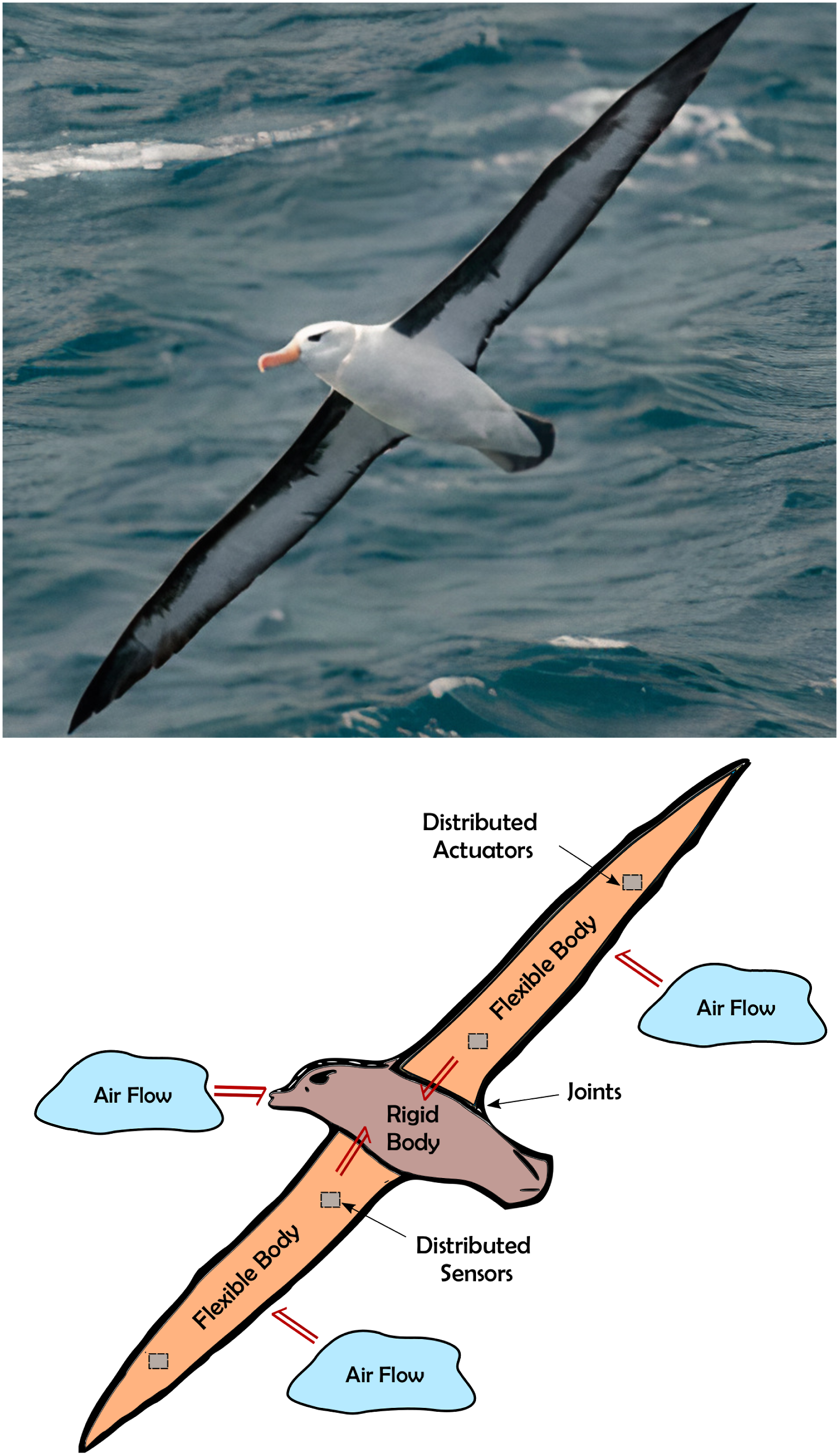
2.1. Modeling of main-body dynamics
During the motion of an FWFR in flight, its main body (i.e., fuselage), combined with the tail and wings, is modeled as a floating open kinematic chain subject to gravitational and external aerodynamic forces. The geometric framework of Lie group and screw theory allows a compact and coordinate-free formulation of spatial multi-body dynamics that is widely used in ground-based manipulators (Lynch and Park, 2017; Murray et al., 2017) as well as generic aerial vehicles (Hong et al., 2022). We shall opt for this geometric framework in this section to describe the equations of motion governing an FWFR.
The configuration space of the rigid body is given by the special Euclidean group SE(3). Let {0} denote an inertial frame in 3D Euclidean space and {b} denote an arbitrary body-fixed frame attached to the FWFR’s main body, as illustrated in Figure 2. The configuration of the main body is uniquely determined by the pair Coordinate frames for a flapping-wing flying robot (Robird), including the inertial frame (fixed to the environment) and body-attached frames. The robot has four extensions, two wings, and two tails, each consisting of one segment.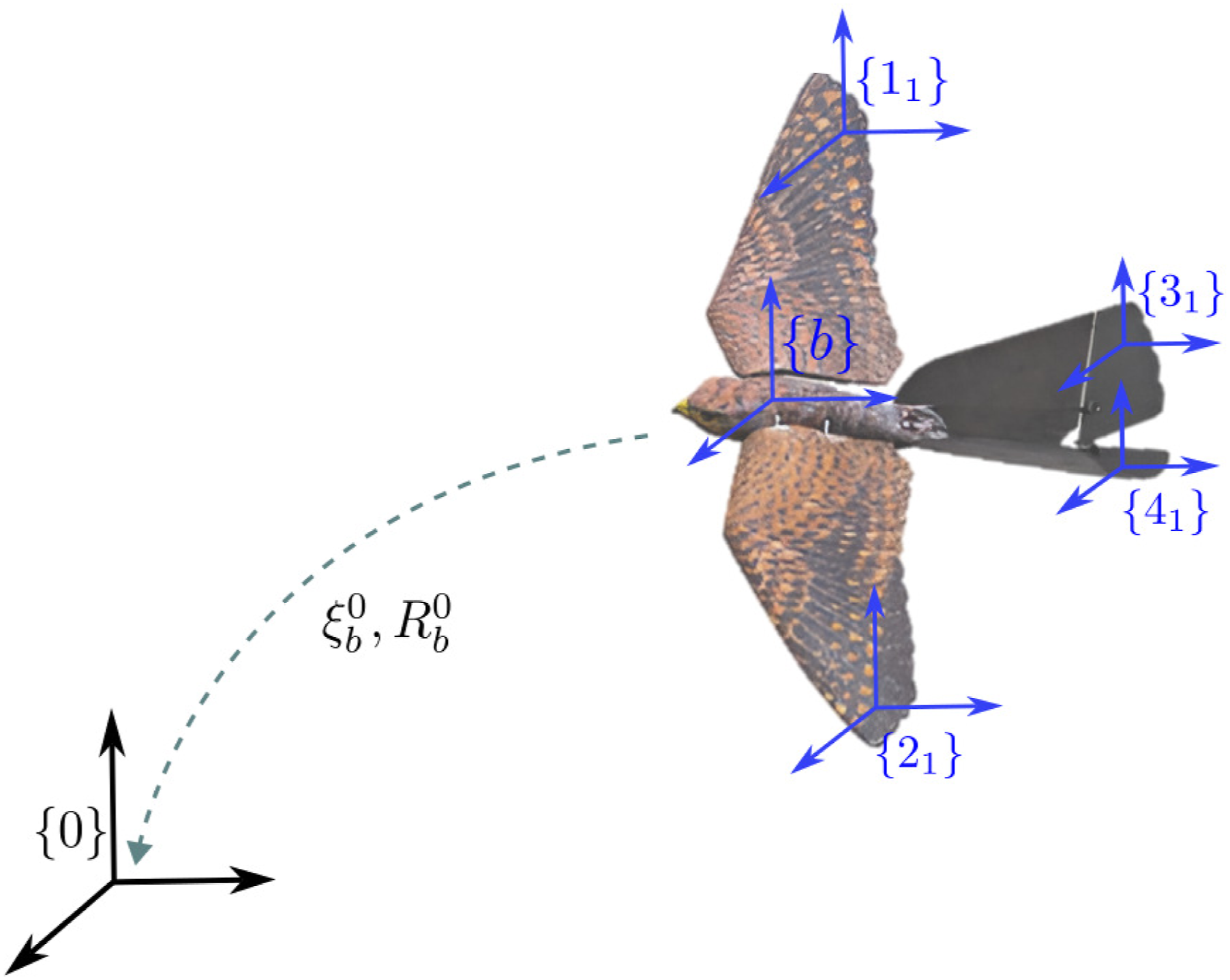
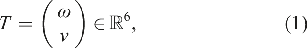
A generic rigid body motion in SE(3) is a combination of translational and rotational motion which are treated in this framework as a single entity, called the twist, which is an element of

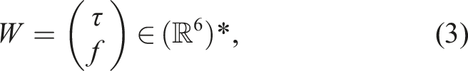
We denote the dual space of
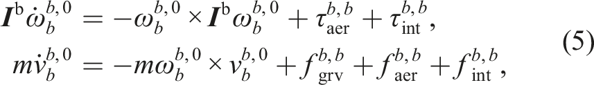
The dynamic equations for the FWFR’s main body (expressed in {b}) are given by the Euler–Poincaré equation (Hong et al., 2022):

An important property of the rigid-body dynamics equation (4) is its invariance under the change of coordinates to any other body-fixed frame (Hong et al., 2022). Note that in general
2.2. Modeling of wing dynamics
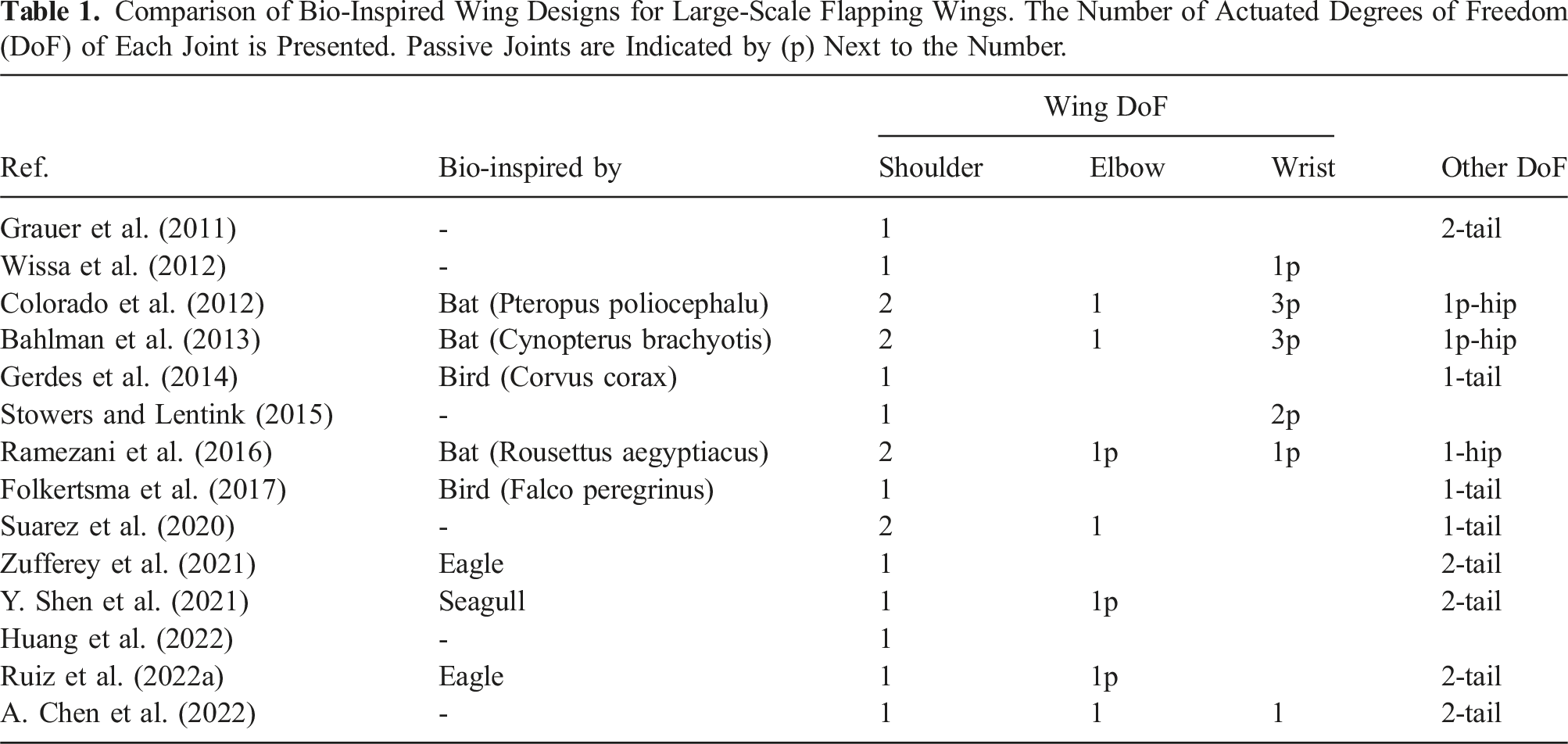
Comparison of Bio-Inspired Wing Designs for Large-Scale Flapping Wings. The Number of Actuated Degrees of Freedom (DoF) of Each Joint is Presented. Passive Joints are Indicated by (p) Next to the Number.
The inherent heterogeneity and anisotropic nature of both engineered and biological wing designs make it essential to resort to the full equations of nonlinear elasticity to mathematically represent the dynamics of a flapping wing with high fidelity (Marsden and Hughes, 1994; Rashad et al., 2023). Some works in the literature that employed this approach include Pfeiffer et al. (2010). However, due to the complexity of the mathematical equations governing nonlinear elasticity and its associated numerical challenges, researchers usually resort to modeling an FWFR’s wing as an articulated serial linkage of rigid bodies. In such multi-body dynamics, the wing’s flexibility is either neglected or approximated at the joints. The development of low-order models that capture the nonlinear elasticity of FWFR wings while remaining suitable for simulation and control requires further exploration and dedicated research efforts. Approaches developed by the soft-robotics community, for example, Mathew et al. (2024), offers a very good source of inspiration that could guide advancements in this area of flapping-wing robotics.
Consider a generic FWFR with m extensions (i.e., wings and tail), each treated as a serial linkage of n
m
rigid bodies connected by n
m
single-DoF joints to each other and to the fuselage. Let {α
i
} denote the body-fixed frame attached to the i-th segment of the α-th extension and let
The internal reaction wrench 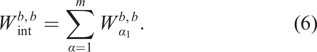
One can then recursively compute the reaction wrenches for each parent–child pair using the joint transformation map Block diagram representation of a parent rigid body {p} and a child rigid body {c} connected through a one-DoF joint defined by the transformation map 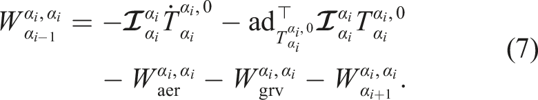
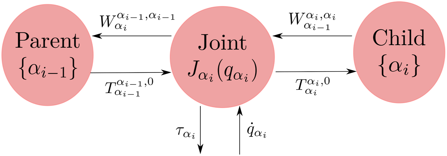
Please note that
The wrenches in the right-hand side of (7) correspond, respectively, to the inertial effects, fictitious (gyroscopic and Coriolis) effects, aerodynamic effects, and the reaction wrench from the subsequently attached body. The details of that formalism can be found in Hong et al. (2022).
Note that in the aforementioned approach, the resulting dynamic model of the FWFR has the joint velocities instead of torques as input (cf. Figure 3). Such property is suitable for representing low-level controller dynamics of the joint actuators, for example, servo-motors, that cause the joint velocity to quickly converge to a specified reference one. The joint reference velocities represent the flapping kinematics of the FWFR, which are sometimes predefined by mimicking natural flyers (Taha et al., 2012). Furthermore, for a given profile
Works in the literature that utilized the recursive Newton–Euler formalism described above include (Colorado et al., 2012, 2018). In such works, the FWFR rotational and translational dynamics are usually treated separately, and the roll-pitch-yaw Euler angles have been used to locally parameterize the orientation of the rigid bodies, and the body-fixed frames have been specified using the Denavit–Hartenberg parameters. It is also worth mentioning the work of Abdelbadie (2021), Jahanbin et al. (2016), Karimian and Jahanbin (2020), and Raven Garcia (2023), where bond graph techniques were combined with the Newton–Euler method to graphically represent the energetic structure of the dynamic model.
Alternatively, several dynamic models of FWFRs with torque inputs have been proposed in Ramezani et al. (2015), Ruiz et al. (2022b), Y. Shen et al. (2021), and Suarez et al. (2020) which in general consist of a combination of the Euler–Poincare equation (4) and Euler–Lagrange equations corresponding to the motion of the main body and wings shape, respectively. Such models take the generic form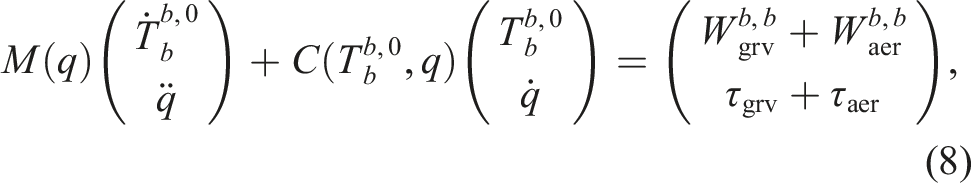
The configuration space
Though the mathematical models described above accurately describe the behavior of an FWFR, various assumptions are utilized to streamline the model’s complexity, depending on the type of robot involved. For insect- and small-size FWFRs, each wing is usually modeled as a single body with a very high flapping frequency
2.3. Modeling of aerodynamics
To develop a high-fidelity mathematical model of flapping flight, the viscosity of the airflow and the generation of vortices are essential aerodynamic phenomena that should be taken into account (D. D. Chin and Lentink, 2016). Consequently, linear or ideal assumptions, which are standard in modeling airflow interaction with fixed-wing vehicles, cannot be made for flapping-wing ones, and the full Navier-Stokes equations should be used. The aerodynamic wrench
With regards to the aerodynamic wrench
The computational efficiency of state-of-the-art computational fluid dynamics (CFD) software for fluid-structure interaction has still not reached a level of maturity to be used for aerial robotics applications. A simulation of one flapping cycle, for low-to-intermediate Reynolds number, could be in the order of hours (H. Liu and Aono, 2009). Therefore, researchers usually resort to surrogate models to approximate the aerodynamic wrenches acting on a flapping wing. This broader topic of fluid–structure interaction surrogate modeling also applies to underwater vehicles, wind turbines, and other fields of engineering. In what follows, we focus our review on aerodynamic models that have been employed within the context of flapping-wing aerial robotics. The reader is referred to Ansari et al. (2006), Shyy et al. (2010a), Taha et al. (2012), and Xuan et al. (2020) for complementary reviews on the aerodynamics of flapping wings.
The majority of works rely on the experimental identification of the aerodynamic wrench acting on a flapping wing using wind tunnel measurements. Some works rely on experimental setups of a single flapping wing, such as Bahlman et al. (2013), Chang et al. (2020), A. Chen et al. (2022), Folkertsma et al. (2017), and other works identify the resultant aerodynamic wrench on the FWFR as a whole, such as Ajanic et al. (2020), A. Chen et al. (2024), Colorado et al. (2012), and Gerdes et al. (2014). A different experimental approach that was used to identify the aerodynamic wrench on an FWFR as a whole is the work of Grauer et al. (2011) where the aerial robot’s states were observed using a motion capture system and the dynamic model of the robot (4) was used to compute the applied aerodynamic wrench.
Works that utilized CFD simulations include Ruiz et al. (2022a), Suarez et al. (2020) and X. Wu et al. (2022). Ansys Fluent software has been used in Suarez et al. (2020) to analyze the aerodynamic effects of different configurations of the wing joints on the aerodynamic characteristics of a flying robot. The aerodynamics of their FWFR were analyzed relying on CFD simulations where the Reynolds-averaged Navier-Stokes equations were solved (X. Wu et al., 2022). A reduced-order model was utilized and constructed by dimensionality reduction from high-fidelity CFD simulations (Ruiz et al., 2022a). The reduced-order model was a model-based technique based on the Volterra series that was able to describe time-invariant nonlinear systems with fading memory.
An alternative to expensive CFD and wind-tunnel approaches is to use semi-empirical quasi-steady aerodynamic models, which are favorable in aerial robotics due to their balanced compromise of fidelity and simplicity (Ansari et al., 2006). Such models are usually used to describe the unsteady aerodynamics with empirical formulae and basic principles, where the former are produced mainly using wind tunnel measurements and sometimes using CFD, for example, as in Nakata et al. (2015) and X. Zhao et al. (2023). Using blade element or strip theory, the constructed formulae are applied to chord-wise strips distributed along its span. In this manner, the spatial heterogeneity of the wings is taken into account, which provides a tractable means of calculating instantaneous forces from defined or generated wing kinematics.
One of the aerodynamic models that are widely used for the FWFR is the quasi-steady model of Dickinson et al. (1999) and Sane and Dickinson (2002). This model is empirically fitted for insect-sized wings in low Reynolds number flows and high flapping frequency. It provides a prediction for the instantaneous lift and drag forces correlated to three degrees of freedom flapping kinematics parameterized by the angle of attack, flapping velocity, and wing shape. This model has been utilized for insect-scale robots (Armanini et al., 2016). In addition, it has been used for some bird-scale ones (Y. Shen et al., 2021; Stowers and Lentink, 2015) to give a crude assumption of the aerodynamic forces.
Based on thin airfoil theory, Peters et al. (2007) proposed an aerodynamic model that was broadly utilized (J. Choi et al., 2021; Pan et al., 2021; Xu et al., 2019). The model of Peters et al. (2007) improved upon the classic model of Theodorsen that can incorporate large wing motions, unsteady freestream, and three-dimensional wake structures. Goman and Khrabrov (1994) presented a model for oscillating airfoils applicable to high angles of attack. It incorporates a nonlinear expression for lift, valid also for post-stall angles of attack, as well as the chord-wise movement of the separation point on the wing’s upper surface, which models delayed stall conditions. A similar nonlinear model is used for computing the quarter-chord pitching moment (Paranjape et al., 2012, 2013; Ramezani et al., 2015, 2016). Other aerodynamic models that have been employed in the literature include the unsteady vortex lattice method applicable for both insect-scale (Roccia et al., 2013) and bird-scale wings (Savastano et al., 2022).
Following the review in Section 2.2 on the development of low-order models that capture the nonlinear elasticity of wings, future research on lower-order models that capture the aerodynamics of the FWFRs is needed. Data-driven models based on machine learning are a promising, unexplored area of research for the FWFRs. The recent advancements in reinforcement learning (RL) in the robotics community could be applied (Tu et al., 2021). This has been very recently shown by T. Kim et al. (2024), who employed RL for the control of an insect-sized FWFR trained in a wind tunnel. There will be more research in the future on the control of the FWFRs using RL. Thus, training with simulations could be done similarly to the recent advancements in legged robotics, for instance, as in Lee et al. (2024). For such simulation environments to be suitable for RL training, we believe aerodynamic models will still play a fundamental role in capturing the aerodynamic interaction between the FWFRs and their environment.
2.4. Port-Hamiltonian framework
In this section, we discuss the interplay between the geometric port-Hamiltonian framework for energy-based modeling and the FWFRs. The challenges of understanding flapping flight and developing bio-inspired FWFRs have driven significant advancements in the port-Hamiltonian theory (cf. Figure 4). Conversely, the port-Hamiltonian framework provides a robust foundation for the modeling, simulation, and control of the FWFRs. Snapshot from the PORTWINGS project video on how the geometric port-Hamiltonian framework can be used for understanding flapping flight and the development of robotic birds, (link to video).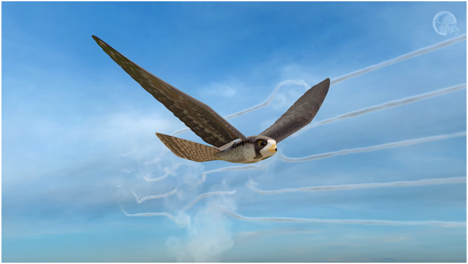
The port-Hamiltonian framework has a number of unique attributes that make it a suitable candidate for the dynamic modeling of the FWFRs. First, the models of the subsystems shown in Figure 1 consist of both finite- and infinite-dimensional systems. In particular, the multi-rigid body model is a finite-dimensional system represented by ordinary differential equations, whereas the airflow and flexible body models are infinite-dimensional systems represented by partial differential equations. Thanks to its geometric global and unified formulation, the port-Hamiltonian framework can incorporate both types of differential equations using differential geometric tools. Such capability has been demonstrated, for instance, in modeling open kinematics chains with both rigid and flexible links (Macchelli et al., 2009) as well as generic fluid–structure interaction (Califano, Rashad, Schuller, and Stramigioli, 2022).
Second, as discussed in Section 2, the full Navier-Stokes equations have to be used for high-fidelity estimation of aerodynamic wrenches, which are a nonlinear, infinite-dimensional, and dissipative dynamical system. Although other standard frameworks, such as the Hamiltonian and Lagrangian ones, can handle nonlinear infinite-dimensional systems, they are only limited to conservative dynamical systems. On the contrary, the port-Hamiltonian framework overcomes this limitation by exploiting certain mathematical structures, known as Dirac structures, that allow handling complex dissipative systems. The Navier-Stokes equations have been extensively studied within the port-Hamiltonian framework in Califano et al. (2021b), Califano et al. (2022b), and Rashad et al. (2021a, 2021b; 2021c), which have shown the rich mathematical structure underlying these differential equations.
Third, to describe fluid or structural dynamics as open systems that could be attached to other systems to represent a multi-domain dynamical system, such as the FWFR in Figure 1, generic variable boundary conditions of each subsystem need to be incorporated. A major limitation of the traditional Hamiltonian treatment of infinite-dimensional systems is that it handles only classes of boundary conditions that result in zero-power exchange through the boundary (Van der Schaft and Maschke, 2002). Such a framework only allows representing systems that are isolated and not part of a bigger dynamical system. On the other hand, the port-Hamiltonian framework allows for non-zero power exchange through the boundary and within the spatial domain. In the case of a nonlinear elastic model of an FWFR’s wing, this power exchange through the boundary corresponds to power due to stress forces (Rashad et al., 2023; Rashad and Stramigioli, 2024). This eventually leads to the aerodynamic wrench
Fourth, the port-Hamiltonian framework is capable of incorporating multi-domain physical systems in a unified approach since it is based on the principle of energy conservation. As a result, the same mathematical representations and concepts can be used for the different physical domains available in the model of flapping flight, that is, structural mechanics and fluid mechanics. In addition, such property is also useful for the modeling of smart material-based actuators, for example, piezoelectric (Macchelli et al., 2004) and shape-memory alloys (Rizzello et al., 2019), which will include the thermal and electromagnetic domain as well. Such actuators have been incorporated in several FWFR designs to resemble artificial muscles, for example, in Colorado et al. (2012), Furst et al. (2012), D.-K. Kim et al. (2008), and Perez-Sanchez et al. (2021).
The port-Hamiltonian framework not only equips one with tools to unify the treatment of different physical domains but also bridges the gap between modeling, simulation, model-order reduction, and model-based control. For a given dynamical system expressed in the port-Hamiltonian framework, one can exploit the underlying structure of the equations of motion to develop structure-preserving discretization schemes that make the physics-based simulation energetically and physically consistent (Brugnoli et al., 2021, 2022, 2023). Similarly, such underlying structure can be exploited to develop efficient preconditioning algorithms for speeding up simulations (Güdücü et al., 2022), structure-preserving model-order reduction that could be used for optimization and control (Chaturantabut et al., 2016), and energy-based controllers that enable robots to physically interact with unknown environments (Rashad et al., 2019, 2022). The application of the port-Hamiltonian framework to the FWFRs via structure-preserving simulations, model order reduction, and model-based control is an unexplored area of research. In particular, the use of an FWFR for aerial-physical interaction is currently an ambitious active area of research (Ollero et al., 2021), and the port-Hamiltonian approach, particularly its control-by-interconnection methodology, was shown to have promising potential (Rashad et al., 2022).
2.5. Energy efficiency
2.5.1. Small-scale flappers
The total energy efficiency consists of many components and can vary widely based on different propulsion systems. In general, however, the first component is the aerodynamic efficiency of the flapping wings themselves. Of particular interest to very small flappers is that as Reynolds numbers decrease with decreasing vehicle scales, the viscous forces start to dominate. This leads to a decline of the lift-to-power in the function of size, which is steeper in small rotating wing configurations than in flapping configurations (Zheng et al., 2013) and suggests that “aerodynamically,” flapping becomes the preferred solution compared to propellers at very small sizes. In practice, for platforms of 10 g, the difference appears to still be very small (Z. Liu and Moschetta, 2009), and other aspects of the total efficiency, like, for instance, electrical efficiency, will play a prominent role. When including the scaling laws for the actuator, electronics, and mechanism, flapping wings driven by oscillatory actuators also become superior at the fruit fly scale due to the reduction in performance of rotary actuators compared with oscillatory ones at a smaller scale (Hawkes and Lentink, 2016). Overall, efficiency-wise, flapping wings are particularly promising at the smallest scales. More details can be found in Section 3.
2.5.2. Large-scale flapping-wing systems
The energy consumption of a flapping-wing robot can be compared with a fixed-wing platform; multi-rotors and unmanned helicopters might not be good options for energy comparison because their energy consumption is greater than that of the fixed-wing unmanned vehicles. The analysis between flapping and fixed wings is also a challenge since the design of flapping wings is for slow-speed flight, and fixed wings usually fly significantly faster; the control surfaces on the wings and tails are small in fixed wings, and the rudder and elevators of flapping wings are significantly larger. In summary, the flight, maneuver, and turning radius of a fixed-wing plane are different from a flapping-wing system. The following comparisons were done to provide some insights into this matter, and it does not mean one is better than another; energy consumption depends on the application and range of flight.
An FWFR prototype was built to fly outdoors with two rotors on the tip to present a hybrid fixed- and flapping-wing robot (Gayango et al., 2023). The average speed of the fixed-wing mode recorded
Comparison between the flapping and fixed-wing showed a range of 150 − 250 W in 4.5 − 5.4 m/s heading speed, the same platform in flapping resulted in 60 − 140 W in 3.2 − 5.2 m/s (Moreno et al., 2022). The main advantage of the bird-like robots and fixed-wing platforms is the free-of-charge source of energy, wind, that can provide the possibility of gliding in a favorable wind direction. This topic was studied for fixed wings (Escobar-Ruiz et al., 2019; Harvey and Inman, 2021; Lawrance and Sukkarieh, 2009; Yao and Wu, 2019); however, the effect of wind and gliding flight for flapping robots needs more investigation. Devoting more payload to the battery (more capacity) in the system and increasing its weight results in a significant flight time. The conventional battery for short flights weighed 57 g (Zufferey et al., 2021), or 72 g (Pan et al., 2021) provided between 8−15 min flight time; however, increasing the weight of the battery to 247 g showed magnificent 65 min flight time (X. Wu et al., 2022).
The morphing plays a role in energy consumption as well, and the wing is the biggest part of the robot, an ideal place for a morphing design. The surface of the wing in the downstroke provides the lift and thrust force, and in the upstroke, the expanded surface might not be needed. An optimal design of an elbow joint for a folding wing was presented and compared with the rigid wing, demonstrating a higher lift coefficient for the elastic morphing one (Ruiz et al., 2022a). The design of the wing is a critical issue, but the morphed wing presents a smaller surface for the wing in the downstroke as well, reporting approximately similar lift power for a bat flapper (Gong et al., 2021).
Energy optimization can be enhanced through the selection of low-consumption equipment for the robot. A camera is an essential part of the FWFR for monitoring and non-contact inspection; the event camera was compared with a conventional RGB one and recorded significantly lower energy usage (Tapia et al., 2023). The last point on the energy is harvesting the power using solar panels; the big surface of the wing is a perfect place for setting them up (Perez-Rosado et al., 2015a). Considering that in windy/rainy weather conditions, even some real birds do not fly, sunny weather is expected normally for performing the flights, then it suggests more investigation on the installation of the solar panel on the body of the robot. More details can be found in Section 4.2.
3. Small-scale and insect-sized flapping-wing systems
Small-scale flapping-wing robots present unique opportunities (De et al., 2022; G. De Croon, 2020); they will be able to fly in narrow spaces and are extremely safe due to their low weight and soft wings. Moreover, as the wings will typically touch any obstacle at a low speed because the wing reverses direction at the end of its stroke, many flapping-wing drones can deal well with collisions (cf. H. V. Phan and Park, 2020). All these properties make small-scale flappers very well-suited for indoor applications. Indoor environments are narrow and cluttered, and safety for any humans or animals present in these environments is essential. Moreover, the natural appearance and sound of flapping-wing drones enhance the acceptability of flapping-wing drones. This opens the door to applications in which humans may work alongside drones, for example, in warehouses or greenhouses.
On the other hand, the size and weight constraints lead to considerable challenges for small-scale flapping-wing drones. The design of them,
Besides design challenges, the flight range and endurance of small drones are also major concerns. For this aspect, though, some small-scale flapping-wing drones have the attractive property that they have a wide “flight envelope,” meaning that they can hover and fly forward and even backward at various velocities. Importantly, as shown in Section 2, the aerodynamic efficiency varies over the flight envelope. For small-scale models, this can significantly extend the flight time. For example, the 16-g DelFly II has been recorded to fly for 22 minutes and 33 seconds when flying on average at 5 m/s, covering
As the size diminishes to approximately a gram, a power advantage is derived that comes from scaling physics. At that scale (given by ℓ), powering flight indefinitely from the sun may be possible. The power collected from the sun scales as ℓ2, while the power needed to fly scales downward more quickly as ℓ7/2 ≈ ℓ3. The crossover scale at which the array size needed for indefinite flight is less than the size scale is approximately 1 g (Elkunchwar et al., 2021), and recent results demonstrated “solar break-even” on a rotor-powered aircraft at that scale (W. Shen et al., 2024).
In this section, we will first discuss small-scale flapping-wing drones,
3.1. Small-scale flapping-wing drones
Small-scale flapping-wing drone designs have heavily drawn upon previously existing rubber-band-powered ornithopters, which have been around since the 1870s (Chanute, 1997). In these flappers, the crucial wing morphing, described in Section 4.1.2, was obtained using flexible membranes as wings, in which the air passively changed the camber during the stroke. The combination of finite- and infinite-dimensional systems in Section 2.4 could be used to model these flapping systems. Combined with advances in micro-electronics, this allowed for the first electric-powered flapping wing drone, the MicroBat, in 1998 (Pornsin-Sirirak et al., 2001) (Figure 5(a)). A first design used two 1-farad supercapacitors to fly for 9 seconds, while a later prototype used a Ni-Cad battery to achieve a flight time of 42 seconds. A selection of small-scale flapping-wing drones. (a) 1998 tailed MicroBat (Pornsin-Sirirak et al., 2001); (b) 2013 tailed DelFly Explorer (G. De Croon et al., 2016); (c) tailless Nano hummingbird (Keennon et al., 2012); (d) tailless KU Beetle (H. V. Phan et al., 2020).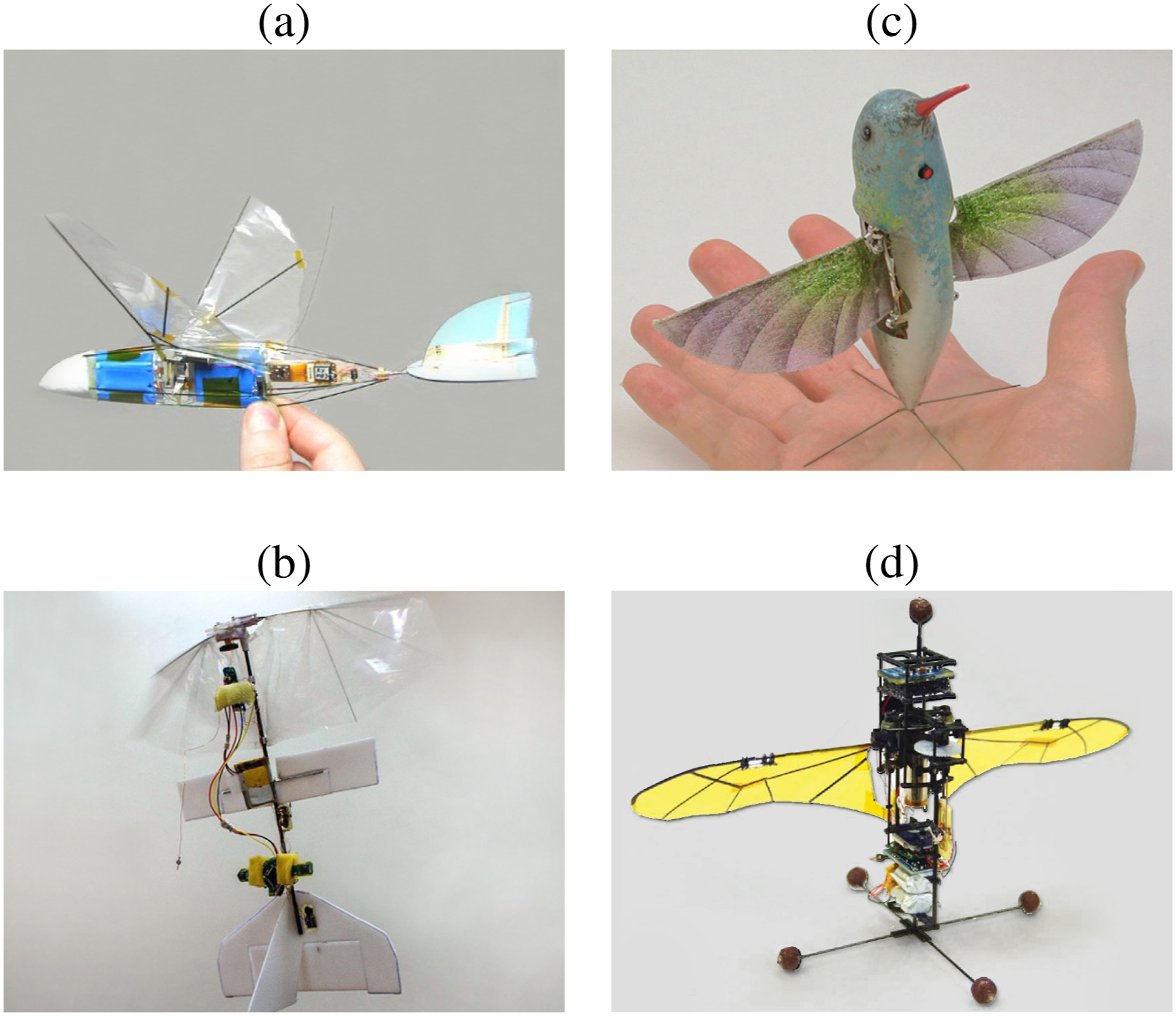
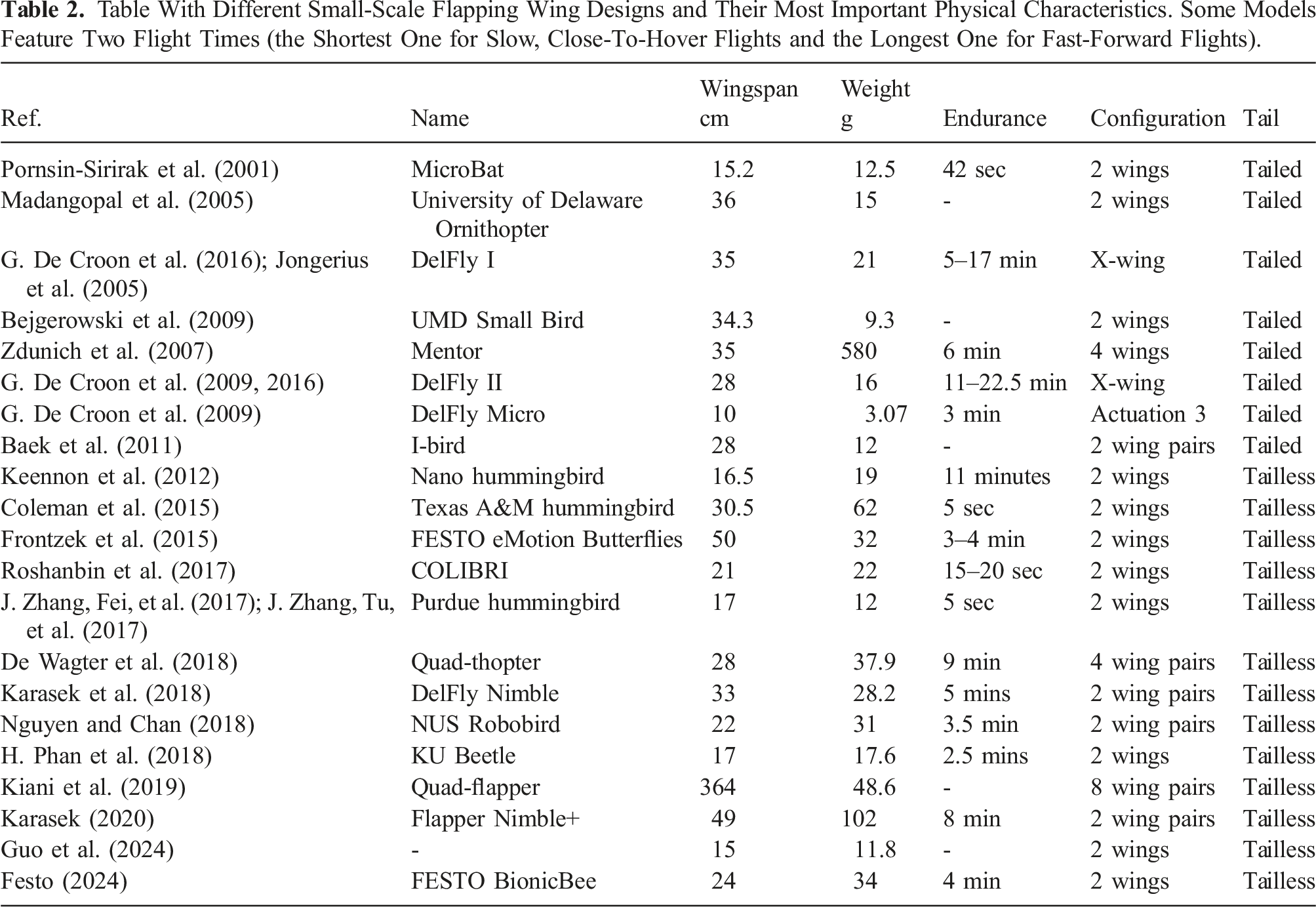
Table With Different Small-Scale Flapping Wing Designs and Their Most Important Physical Characteristics. Some Models Feature Two Flight Times (the Shortest One for Slow, Close-To-Hover Flights and the Longest One for Fast-Forward Flights).
3.1.1. Tailed designs
Initial designs used the wings only for thrust generation and used a plane-like tail (Figure 10) for attitude stabilization and control (Bejgerowski et al., 2009; Jongerius et al., 2005; Madangopal et al., 2005; Pornsin-Sirirak et al., 2001). The lift generated by the tail surface in forward flight has a passively stabilizing effect on the drone’s attitude. Given the correct center of gravity, an increase in the angle of attack of the entire flapper results in the tail creating a downward pitch moment to stabilize the platform (Koopmans et al., 2015). Active elements on the tail, such as a rudder and elevator, can then be used to introduce moments, for example, pitching and yawing.
The advantage of tailed flapping-wing drones is that, in forward flight, they do not need onboard attitude estimation and control. A major disadvantage is that the actuator effectiveness of the active tail surfaces depends strongly on the airspeed. In a windstill environment, hovering then becomes a considerable challenge (Verboom et al., 2015) as the tail surfaces have very little control authority. On the other hand, the control gains should be scheduled with airspeed, as with increasing airspeed, the surfaces generate larger moments. Finally, the drag of the tail exacerbates the problem of susceptibility to wind and wind gusts.
3.1.2. Tailless designs
Insects control their motion by changing their wing dynamics. Besides the nominal flapping motion and passive wing morphing, the flapping motion requires additional degrees of freedom. The “Nano hummingbird” was the first tailless flapping wing drone to demonstrate this in a free-flying prototype (Keennon et al., 2012) (Figure 5(c)). The main advantage of this type of design is that direct control over the main flapping forces results in much bigger generated moments. This enhances the drone’s control authority, making it less sensitive to gusts than tailed designs and enabling it to hover and perform agile flight maneuvers. For example, the “DelFly Nimble” was able to mimic agile fruitfly escape maneuvers so closely that it helped explain the dynamics of these maneuvers (Karasek et al., 2018).
Since the Nano Hummingbird, several tailless flapping wing designs have been introduced, with different designs for generating pitch, roll, and yaw moments. For instance, the Nano Hummingbird (Keennon et al., 2012), Colibri (Roshanbin et al., 2017), and KU Beetle (H. V. Phan et al., 2020; H. Phan et al., 2018) changed the wing twist over the flapping cycle to generate moments. For example, if the left wing has a higher angle of attack over the flapping wing cycle than the right wing, the flapper will roll to the right. Pitching forward is achieved by having a higher angle of attack on the backstroke compared to the front stroke. Finally, yawing is achieved by having a higher angle of attack for the forestroke of one wing and the backstroke for the other wing. In contrast, the robotic hummingbird from Purdue (J. Zhang, Fei, et al., 2017) and the DelFly Nimble (Karasek et al., 2018) vary the center of the wing stroke to generate pitch. These designs generate roll moments in a different manner. Designs such as the DelFly Nimble (Karasek et al., 2018) and the NUS Robotic bird (Nguyen and Chan, 2018) create roll moments by differentiating the left and right flapping frequency. Instead, the Purdue hummingbird (J. Zhang, Fei, et al., 2017) changes the flapping amplitude for roll moment generation. Furthermore, yaw moments of the DelFly Nimble are generated by twisting the wing roots. The Purdue hummingbird changes the flapping amplitude mid-cycle so that one wing has a larger amplitude on the forestroke while the other has a larger amplitude on the backstroke. Finally, less bio-inspired designs have been proposed, such as the “quad-thopter” (De Wagter et al., 2018). As the name suggests, the “quad-thopter” has a similar design to quadrotors, with the rotors replaced in this case by double wings. Roll and pitch generation is performed by driving the four wing pairs at different frequencies. Moreover, yaw moments are achieved by placing the wing pairs obliquely. A recent flapping-wing robot, Festo’s “Bionic Bee,” twists the wings and rotates the flapping mechanism to perform thrust vectoring to achieve the desired control moments.
3.2. Insect-sized flapping-wing drones
The major design categorization that we use to distinguish “small” from “insect-sized” drones is the absence of an electromagnetic rotary motor. A key constraint that drives the design of insect-sized (
The physics of small scale largely eliminates using rotary electromagnetic motors because of prohibitive increases in losses in the coil. If it is assumed that the magnetic coils are operated at the limit of their ability to dissipate heat before melting (to get the highest power-to-weight ratio), then coil losses vary in proportion to the length scale of the aircraft (∼ℓ), which means that power dissipation per unit volume ∼ℓ−2 (Trimmer, 1989). A reduction in scale by a factor of 10 is accompanied by a 100-fold increase in the relative amount of power dissipated. Furthermore, friction losses in gearing increase relative to the energy produced by the motor because Coulomb friction scales with area (∼ℓ2), whereas energy available from a battery ∼ℓ3.
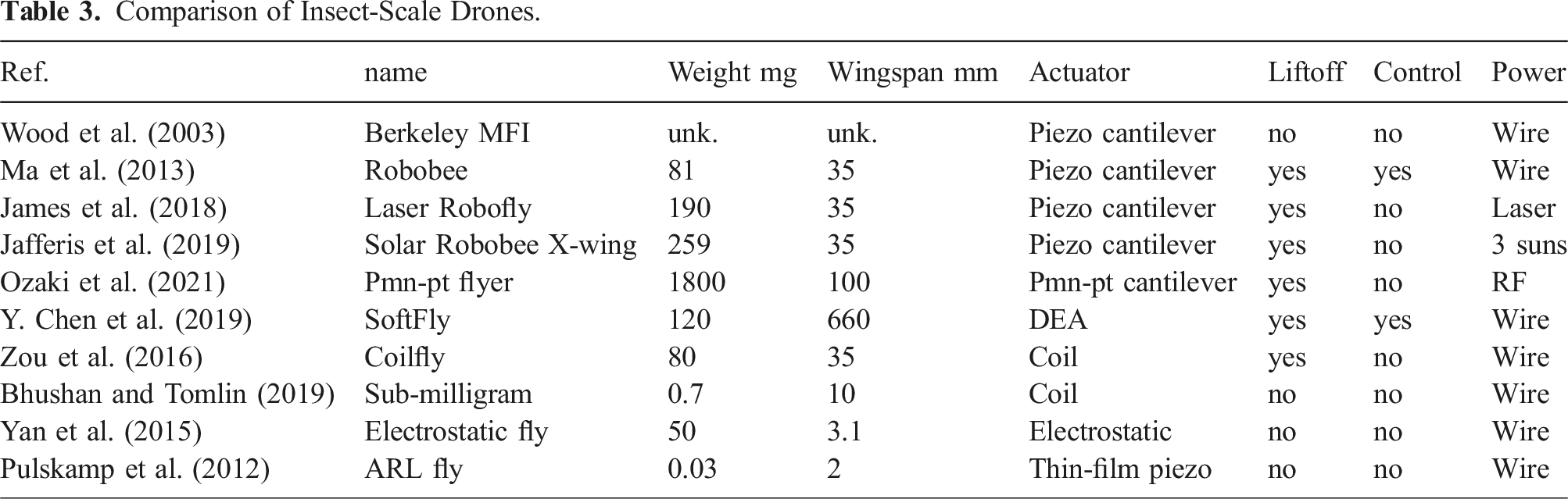
Comparison of Insect-Scale Drones.
Fabrication of Insect-Sized Drones. Two main approaches have been attempted. The first is to build a mechanical structure on a silicon wafer using lithographic approaches derived from the semiconductor industry. This approach is capital- and time-intensive, but can produce extremely small features 1 μm or smaller. A process known as “Smart Composite Microstructures” (SCM) was introduced in Wood et al. (2008) that entails laser-based micromachining that is well-suited to slightly larger features measuring 10−20 μm. Comprising a short-wavelength laser in the 532–355 nm range, thin layers of material are individually cut, bonded using a sheet adhesive, and then subsequently featured in the part guide, folding into a desired 3D shape. Such lasers can ablate nearly an unlimited material set, allowing for parts made from metals, carbon fiber composites, and piezoelectric ceramics.
3.2.1. Piezo-actuated insect-sized drones
Early on, Berkeley’s MFI (micro-flying insect) recognized that electrostatic actuators could outperform magnetic actuators at a small scale, so early prototypes quickly settled on this as their actuation technology (Wood et al., 2003). After transitioning from metal to lighter-weight carbon fiber, the MFI attained a high flapping frequency but was unable to lift its own weight due to a complex mechanism (Figure 6) A key innovation by one of the graduates of that program, Rob Wood, was to allow the angle of attack to rotate freely rather than actuating it, which dramatically reduced weight and led to a lift greater than weight (Wood, 2008). A later incarnation explored an insect-inspired approach to control that separated power actuators from control actuators (Finio and Wood, 2012), but an alternative design composed of two independent actuators, both of which could provide power and control, turned out to be lighter, simpler, and capable of the first controlled hovering flight of a sub-gram aircraft (Ma et al., 2013). Insect-sized flapping-wing systems actuated by piezo. (a) Berkeley Microrobotic Fly (Wood et al., 2003) constructed from composite materials; (b) Harvard Robobee attained first controlled flight (Ma et al., 2013); (c) U. Washington attained the first untethered flight (James et al., 2018); (d) Toyota employed compliant PMN-PT material to introduce a simpler direct-drive actuator, and radiofrequency-powered flight (Ozaki et al., 2021).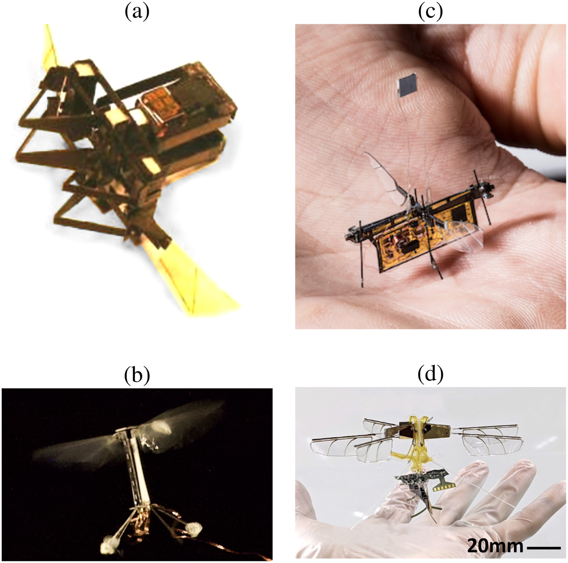
Newer piezoelectric materials, for example, single-crystal PMN-PT (lead magnesium niobate-lead titanate), have the potential for higher efficiency and energy-per-weight than PZT (lead zirconium titanate). A design that exploits this idea was shown in Ozaki et al. (2021) and was able to attain untethered flight.
At the very smallest extremes, piezoelectric material can be directly deposited, but only in very thin layers (
3.2.2. Coil-actuated insect-sized drones
The drone in Zou et al. (2016) attained liftoff using an airframe fabricated using SCM-derived processes (Figure 7). Magnetic coils have distinct advantages over piezoelectric actuators, including a low voltage (1.1 V in this case) and no chance of cracking, but it remains to be seen whether efficiency can be improved. The coil consumed approximately 1.2 W for a lift of 80 mg, which equates to an efficiency of 0.65 mN/W. More recently, Bhushan and Tomlin (2018) introduced a coil-actuated design that improved efficiency threefold to 2 mN/W, but this is far below that of the best combined piezo and voltage boost circuit efficiency of 23 mN/W reported in Jafferis et al. (2019). Insect-sized flapping-wing devices actuated by other technologies. (a) Electromagnetic coil (Zou et al., 2016); (b) sub-milligram coil (Bhushan and Tomlin, 2019); (c) microgram scale thin-film piezo material (Pulskamp et al., 2012); (d) dielectric elastomer (Y. Chen et al., 2019); (e) electrostatic (Yan et al., 2015).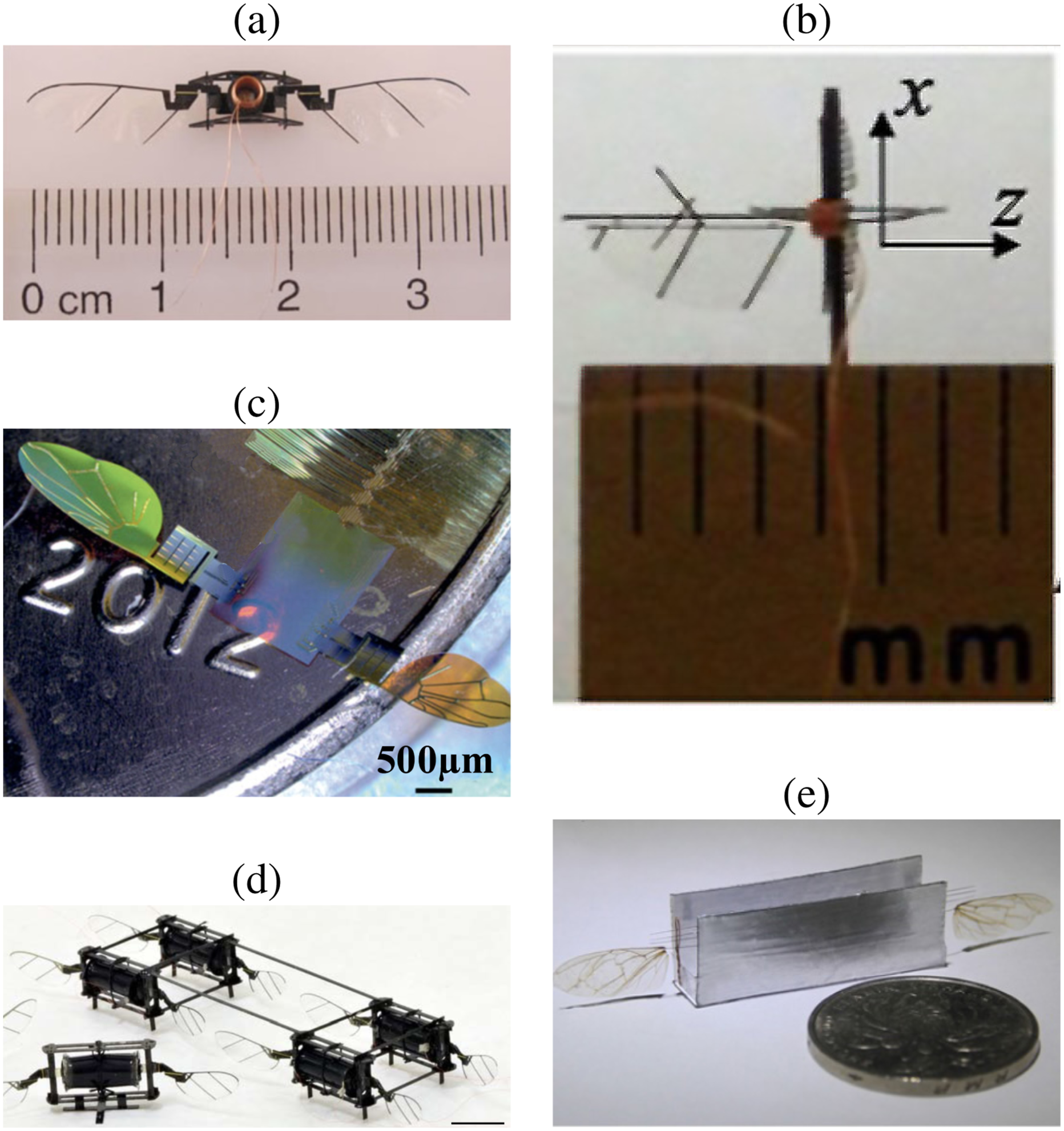
3.2.3. Electrostatically-actuated insect-sized drones
A 600 mg aircraft actuated by a dielectric elastomer actuator demonstrated controlled flight in (Y. Chen et al., 2019). This is a promising alternative to piezoelectric cantilever actuators because of a lack of cracking, but it requires high voltage (600 V–2 kV), and it is not known whether it can obtain an efficiency that is compatible with battery-powered flight. A pair of wings weighing 3 mg actuated by electrostatic actuators was able to lift off, suggesting the potential of this technology (Yan et al., 2015). Key challenges include that this reported mass does not include the required electrodes, which are substantially more massive and require a high voltage of 5 kV.
4. Large-scale systems
4.1. Flapping wing systems
4.1.1. Thrust and lift generation and control
Birds flap to generate thrust and lift at the same time. Different flapping mechanisms can be used to obtain the reciprocating flapping motion, including one motor and effective transmissions or two independent servomotors to drive wings on laterals, with more maneuverability in theory.
Understanding the structural, aerodynamic, and behavioral patterns of natural flyers is needed for developing robust and high-performance flapping-wing aerial robots. However, accomplishing this task is no simple feat! Despite extensive research efforts spanning several decades, the flight dynamics of natural flyers are still not fully understood (Floreano et al., 2009), particularly those of bats and birds (D. D. Chin and Lentink, 2016). Small flying creatures rely on high-frequency flapping to produce the required aerodynamics for flight. The flapping frequency (flapping cycles per second) of birds varies according to the type of bird. In Pennycuick (1996), the results of many observations of samples with frequencies lower than 13 Hz were presented. The following expression provides an estimation of the frequency: The definition of the parameters for flapping frequency estimation and up/down stroke.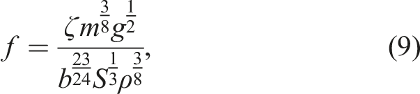
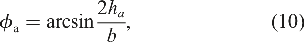
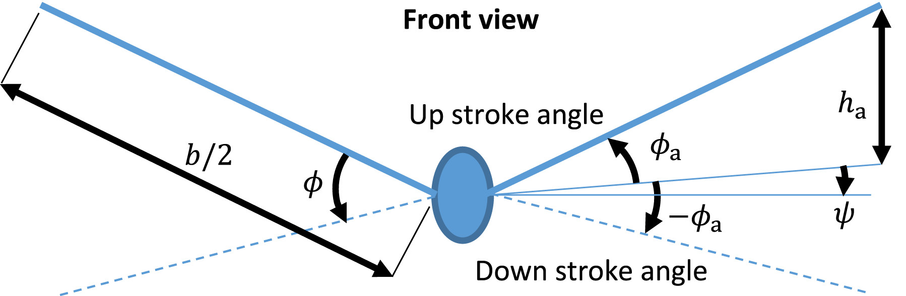
Equations (9) and (10) could be used for estimation of the flapping frequency and initial selection of the flapping angle when a robot is designed and built. The asymmetric movement of the wings during flapping produces the roll, pitch, and yaw moments needed for maneuvering. As seen below, their wings will be accompanied by quick folding in the flapping process. The larger flying animals have simpler basic flapping with their wings flapping almost in a plane when cruising. They also use mechanisms such as flap-gliding and flap-bounding to save energy (Sachs, 2017; Usherwood, 2016). Flapping-wing aircraft mostly cannot achieve basic flight and attitude stabilization at the same time, only by flapping their wings. Then, the tail wing is still required to balance the pitch fluctuation of the body attitude and resist sideslip (see Section 4.1.3).
Natural flyers have remarkable attributes in their locomotion that are challenging to understand and decipher (Shyy et al., 2010b). For example (i) they leverage various aerodynamic mechanisms to generate and enhance lift and thrust, (ii) they avoid obstacles and accommodate wind gusts by employing diverse dynamic and kinematic patterns with their body, tail, and wings (Cuthill and Guilford, 1990; Sarmiento and Murphy, 2018), (iii) they dynamically adjust the structural flexibility of their wings to obtain wing deformations that enhance aerodynamic performance (L. Zhao et al., 2010), and (iv) they have distributed biological units for actuation and sensing across their surface which are crucial for maintaining flight stability in extreme environmental conditions (Shyy et al., 2010b).
Comprehending the aforementioned features of natural flyers requires a deep understanding of their unsteady three-dimensional aerodynamics, boundary and shear layer transitions, dynamic wing morphologies, bilateral fluid–structure interactions, and complex flight dynamics (Shyy et al., 2010b). Once these biological principles are understood, the subsequent challenge lies in abstracting specific desired features and engineering them into aerial robots, a task that is as complicated as the former. The ability to change the morphology of the wings allows birds and bats to perform more versatilely than can be achieved by fixed-wing aircraft. In particular, by reducing the wing area, they can decrease the required energy for fast flight.
4.1.2. Wing
Wings possess the majority of the surface in a flapping-wing robot or an aircraft, hence, they are the major source of drag and lift. The conventional lift force model with flapping wings is given by (Mueller et al., 2010):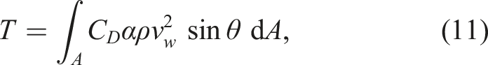
4.1.3. Tail
The tail can play a role in maintaining stability and balance. It generates lift at low speed to effectively reduce induced drag. This induced drag was obtained by Thomas (1996) using Munk’s stagger theorem, which expresses that the total interference drag 4 of any system of wings/tail, is unchanged if the lifting surfaces are moved relative to each other along the line of flight if the total lift remains the same. It also employed Prandtl’s biplane theory, based on the assumption of an elliptic spanwise loading on both wings, according to which the influence on the induced drag of any tail area behind the point of maximum span can be neglected. As a result, the interference drag and total induced drag of the wings and tail are obtained by using Prandtl’s relation.
The flight control of flapping-wing robots is predominantly handled by the tail. Most ornithopters feature a tail with two degrees of freedom. In an FWFR, the longitudinal motion is controlled similarly to any winged aircraft, that is, through the deflection of the horizontal tail surface. However, in ornithopters, the flapping-induced pitch oscillations that perturb both the airflow and the servo actuation require more profound analysis. Additionally, the lack of ailerons significantly increases the difficulty in lateral control. Section 4.2 will present different types of tail configurations to control the ornithopter.
4.1.4. Wind and air currents
Only some large and medium-sized birds in nature have the capability of long-distance flights (Bruderer and Boldt, 2001). When large birds are soaring and gliding, their wings are locked at a specific position and hardly move. This is similar to fixed-wing systems and gliders, which rely on the pressure difference between the upper and lower surfaces of the wings to generate lift to achieve flight (Ejeh et al., 2019). Thus, when the ornithopter’s wings are locked at a certain position within its flapping stroke, it could be considered a fixed-wing aircraft.
Using rising air currents, some large birds can maintain flight without flapping. These birds may alternate glides with periods of soaring in rising air. Thus, the warm air heated by the sun can rise from the hot ground and into the sky, which is so-called “thermal.” Soaring birds can also find rising air in places where the wind is forced to flow up the side of a hill. Smaller objects such as trees or houses produce ridge lift too, though it may not be enough to keep a bird in the air. There is also dynamic soaring, which does not rely on rising air currents (Mir et al., 2018). Instead, it uses the difference in wind speed between the ground and higher up. Dynamic soaring can be used by birds, such as the albatross over the ocean (see Figure 1), to reduce energy consumption effectively, and then finally greatly improve flight efficiency to support continuously flying for months without landing. The challenge here is to imitate the complicated flight mechanisms and strategies of these birds to have very efficient, sustained flights for a long time.
There are different species of birds, including ospreys, kestrels, and kingfishers, that can hover at low altitudes, facing the wind and keeping their heads stationary about the Earth’s surface (Penn et al., 2022; Weyer, 1984). This ability allows them to observe small prey moving below them. Soaring, without flapping the wings, can occur when birds are in the presence of appropriate updrafts on hill slopes. This involves dealing with the atmospheric turbulence typical of these situations. It has been observed that kestrels, when in this hovering position, can deflect their head by less than 6 mm, while exposed to turbulent wind (Penn et al., 2022). Although wind tunnel studies have been carried out to characterize its behavior, the control mechanisms to maintain stability by canceling disturbances are still not well known.
There are also studies on suspended flight by flapping its wings, as the hummingbird does (video), remaining in hovering for one or 2 minutes. Hummingbirds make adjustments to increase force production and improve stability. These adjustments range from modifying the stroke width and flapping plane angle to adjusting the tail fan angle. Furthermore, when in turbulent conditions, they adapt the frequency and amplitude of the flapping, as well as the angle of the flapping plane, the speed of rotation of the tail, and the angle of the tail. However, the energy demand is significantly high in all of these cases. Laboratory studies (Altshuler and Dudley, 2003) were conducted to examine how air density and oxygen partial pressure influence flapping and flapping parameters. The influence of weight has also been studied in different species of hummingbirds, and its relationship with the amplitude and frequency of wing beating to increase the angular velocity of the wings and generate the required lift. The implementation of flight strategies, including the previously mentioned hover flight, makes it essential to continue research into new ornithopter configurations and the corresponding control strategies, using wind sensors integrated with inertial measurement units.
4.2. Morphological characteristics
4.2.1. Size and weight
One of the pioneer large-scale unmanned flapping-wing vehicles (ornithopters) was presented in 2008 (Ueno et al., 2008). The wingspan was 100 cm with wing area of 1605 cm2 and weight of 408 g. The horizontal control was automatic using global positioning system (GPS) feedback, and the attitude was connected to the manual remote controller. A commercial flapping prototype with 35 cm wingspan was used for the installation of a lightweight camera and study of optical flow (Bermudez and Fearing, 2009). The aerodynamics and lift/thrust coefficient computations for low Reynolds numbers were investigated using an experimental prototype (Grauer et al., 2011). The weight of the flapping-wing robot was 0.45 kg, and the motion analysis was done using a visual tracking system due to the limited payload of the robot. Bigger prototypes result in more surface on the wings, which could be used as solar panels for recovering energy for the batteries, since a significant payload of the FWFR can be used by the batteries. The flight time is a function of the power supply as well. In 2015, the use of solar panels on the flexible wings of RoboRaven was investigated (Perez-Rosado et al., 2015b). Despite this obvious benefit of solar panels and the mentioned attempt, nowadays, such a flying FWFR rototype is missing in the recent literature. The computation of the lift coefficient was done through a set of experiments using HITHawk FWFR mounted on stationary sensors for measurements based on airfoil theory (Xu et al., 2019). Sato et al. presented a robot with the possibility of take-off with a wingspan of 760 mm and a total weight of 85 g (Sato et al., 2019). The mentioned systems are a selection of experimental systems in flapping wings with large wingspans between 2008 and 2019, presented in Figure 9. A selection of early-stage prototypes of large-scale FWFRs from 2008 to 2019. (a) A 408 g prototype with 100 cm wingspan (Ueno et al., 2008). (b) A commercial 35 cm wingspan prototype (Bermudez and Fearing, 2009). (c) A 450 g flapping-wing robot (Grauer et al., 2011). (d) A four-link elbow configuration for FWFR (J.-S. Zhao et al., 2014). (e) Passive morphing wings adapted from the bat with 40 cm wingspan (Stowers and Lentink, 2015). (f) Bat (Colorado et al., 2018). (g) Solar panels on RoboRaven (Perez-Rosado et al., 2015b). (h) HITHawk FWFR (Xu et al., 2019). (i) Self-take-off robot (Sato et al., 2019).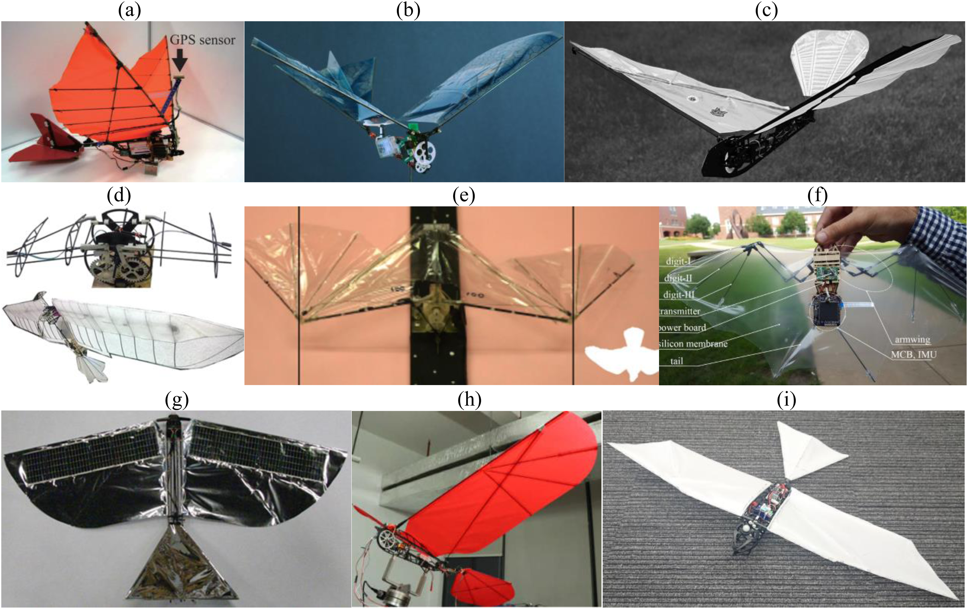
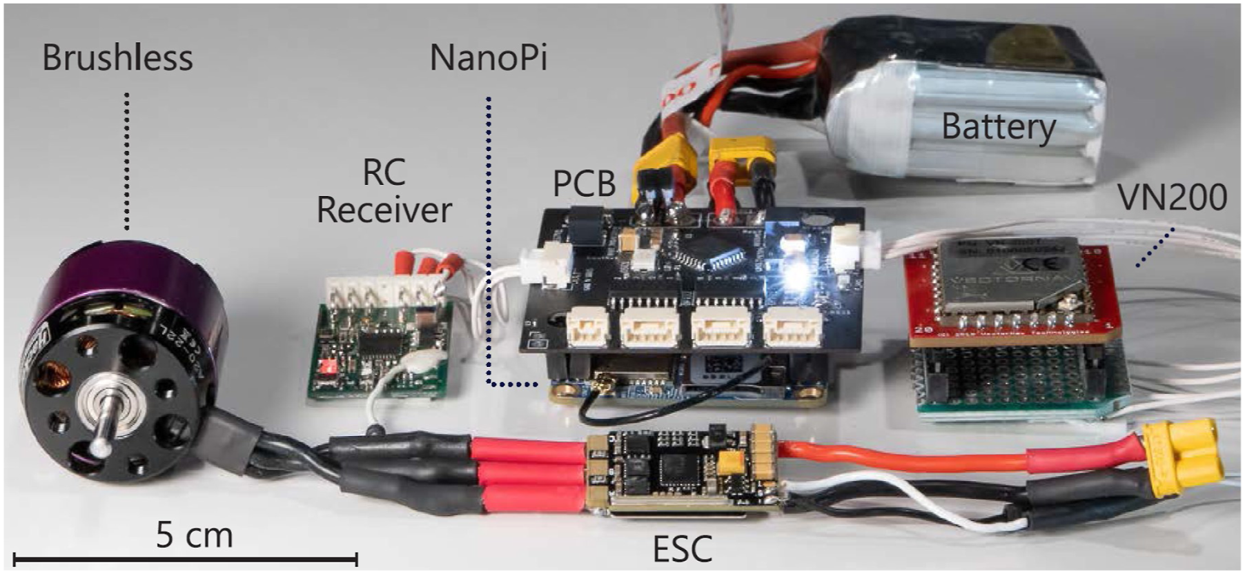
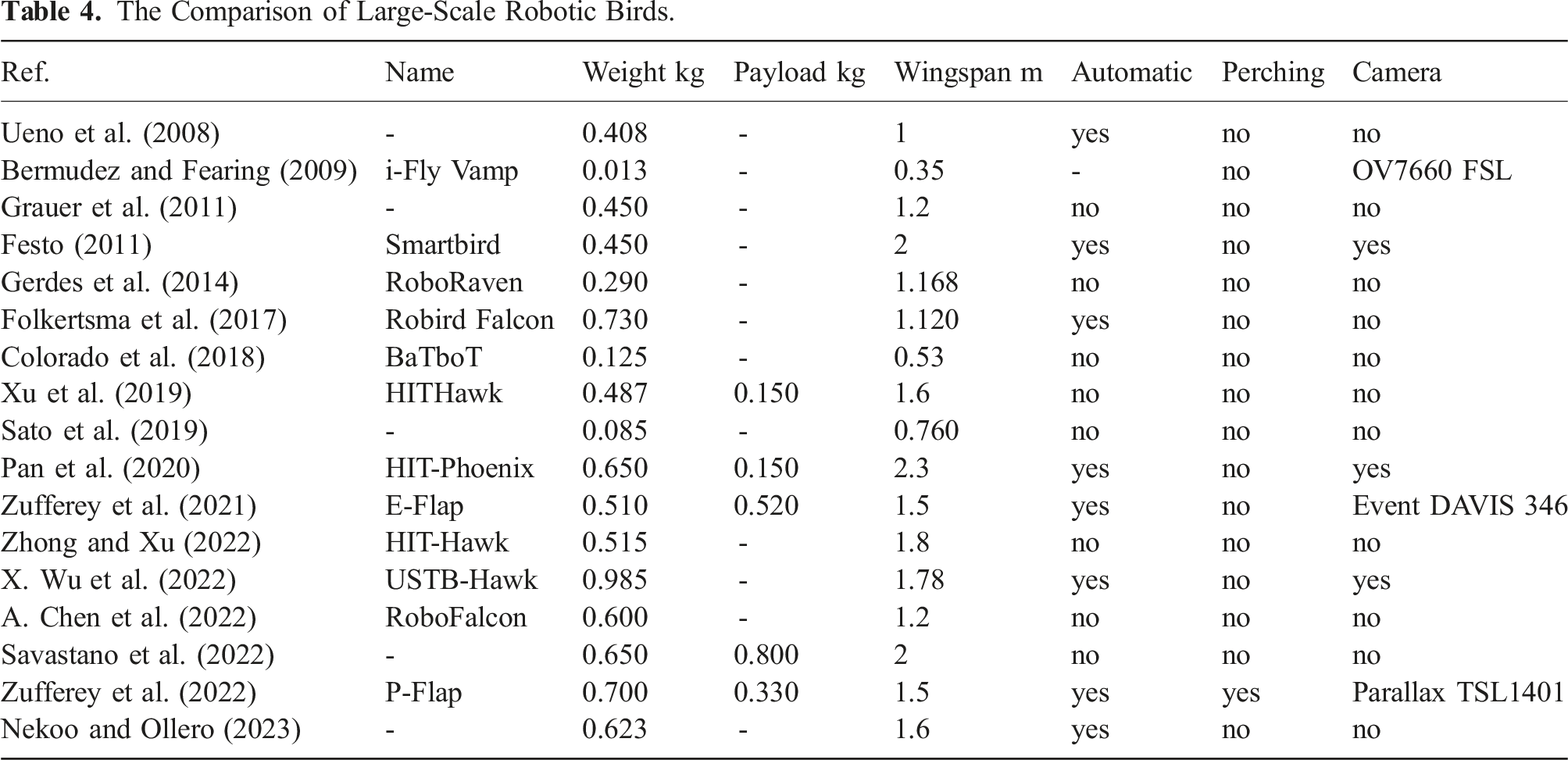
Increasing the wingspan results in more payload for the flying system. The potential items as payload are cameras, sensors, and manipulators. Pan et al. increased the wingspan to 2.3 m for an FWFR with the weight of 650 g and 150 g payload (Pan et al., 2020). The payload was a camera and its stabilizer for monitoring applications. The stabilizer was helpful since the motion of the robot was disturbed by periodic oscillation caused by flapping. The investigation of different types of tails was done, resulting in three categories: D-tail, inverted T-shape, and V-shape tails (Guzman et al., 2021). In all the mentioned tails, two servomotors were used for controlling the bird. The D-tail is closer to bird tails, and the inverted T-shaped tail was adopted from airplanes (Figure 10). Although the three types of tails showed similar longitudinal performance in flight, the inverted T-tail was selected for the design of a high payload E-Flap prototype (Zufferey et al., 2021). The electronics of E-Flap were selected to keep the weight at a minimum rate using customized boards and a Vector NAV VN-200 sensor, which included a GPS and an inertia measurement unit (IMU) on one board, as shown in Figure 11. This robot presented a 510 g platform with a payload of 520 g. Zhong and Xu modeled and experimented with a large 1.8 m-wingspan FWFR in forward flight (Zhong and Xu, 2022). Tang et al. investigated the morphing of flapping raptors using robotic birds (Tang et al., 2022). A comparison of some flapping-wing robotic birds is presented in Table 4. The three types of tail configuration: (a) delta-shaped tail, (b) inverted T-shaped tail, and (c) V-tail configuration. The electronics of the E-Flap prototype; a 510 g robot with 520 g payload (Zufferey et al., 2021). The Comparison of Large-Scale Robotic Birds.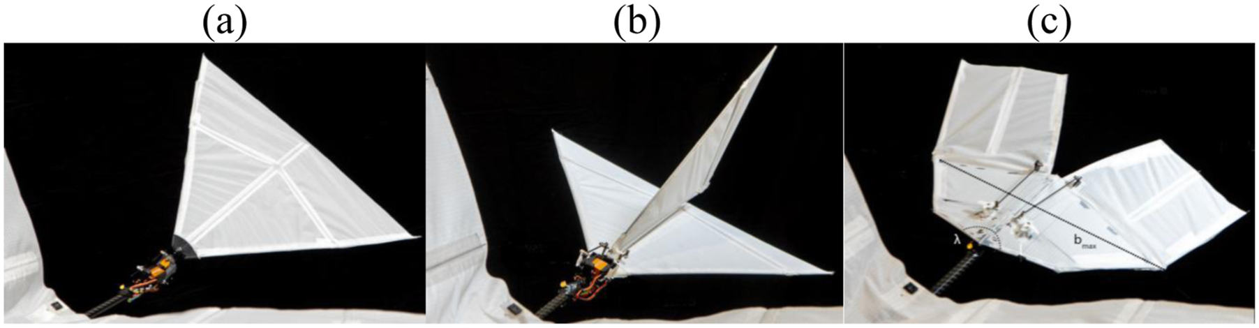
4.2.2. Morphing
Exploring morphing in a flight of a flapping-wing robot is motivated by the application and the performance. The application leads the robots to pass through narrow spaces, increase velocity in diving, change shape after perching, etc. One example reported increased maneuverability of flight for a bat-shaped flapping wing with morphing capability in flight (Colorado et al., 2018). The enhanced performance also provides a natural way of flapping and motion in flight, changing the lift and thrust force, drastic direction changes in flight, etc.
Folding a wing is a way of moving toward bio-inspired prototypes. The wing fold can be represented as a relative rotation of the outer wing part (handwing) about the inner part (armwing). The significant change in the maximum folding angle effectively alters the overall angles of attack. Consequently, by the highest positive lift and thrust decrease, the negative peaks decrease even more significantly. In Fan et al. (2021), the folding of the arm and handwing segments of a bat were studied. Throughout the cycle, the armwing maintained a positive effective angle of attack, while the handwing exhibited a smaller negative angle peak. This was due to the additional flapping motion of the handwing about the armwing, which altered the effective velocity direction of the handwing segment, particularly during the upstroke. Unlike the case when the wing was not folded, the armwing generated positive lift consistently, whereas the handwing produced minimal negative lift during the upstroke. Furthermore, the significant drag experienced by the handwing during the downstroke vanished. This observation indicates that, similar to wing twists, incorporating wing folding could allow for the use of a less powerful motor. In Ruiz et al. (2022a), it was shown how the wing fold using a passive biased elastic joint (biased torsional spring with rigid joint for bending) can be used to increase the payload (16%) and decrease the energy consumption (10%) validated in flight. A bias angle performs an asymmetry between upstroke and downstroke, thus modifying passively the projected area and, hence, the generated lift smoothly. Other types of wing folding were presented as well (Fan et al., 2021; Mu et al., 2022). Y. Shen et al. (2021) presented a design with an elbow joint in the middle of the wings to change the lift coefficient in flight. The mathematical model using open-loop flight data was validated, and linear control design was tested on the platform. The folding wing not only showed more bio-inspired systems but also proved more efficient in flight (Fan et al., 2021).
The maneuverability can also be improved by the wing-tip active tucking. The limited area of the wing is conceived to supply a controlling surface, motivated by the dynamic morphing of limit feathers observed in bald eagles. It is used to imitate the hawk’s distal feathers’ usefulness amid flight. This approach gives a steadier elective to that tail-based control in ornithopters. Here, the morphing method comprises presenting an energetic semi-sweep point, influencing the driving edge shape and, thus, the wing damp range. The strategy depends on the flexible decencies of the double-stiffness leading-edge arrangement. In Savastano et al. (2022), the lower idleness of the external rib granted a semi-folding deformation created by a 0.5 mm nylon wire associated with a root-placed servomotor. The wingtip texture depended on a 1 mm thickness of Smooth-On Ecoflex.
The wingbeat pattern was a nice extension to the topic of folding wings (morphing) that generated a highly agile flapping-wing system for a 1.2 m wingspan robot with 600 g total weight (A. Chen et al., 2022). The folding mechanism reduced the wing surface rapidly, which generated a quick maneuver to the left or right. The flexibility of the large wing and folding of the tip of the wing with a smaller folding area (w.r.t. Ref. (A. Chen et al., 2022)) resulted in a high payload capacity of 800 g in flight (Savastano et al., 2022). More details can be found in a particular review survey on folding wings (J. Zhang et al., 2023).
Morphing can be extended to other parts of the robot, such as the tail. Then, the motion of the tail could be more natural, similar to real birds. Continuous motion is another advantage of morphing in tail design. Microfiber composite was used as actuators of the system for building a bio-inspired tail for a flapping-wing robot (Perez-Sanchez et al., 2021). The actuators showed continuous and unified motion for the tail during the flight tests outdoors.
The integrated modeling and control of a flapping-wing robot with morphing properties is a relevant challenge. The application of the Port-Hamiltonian framework in Section 2.4 could be very valuable to take into account the multi-domain physical properties, including structural and fluid mechanics, in those models.
4.3. Functional characteristics
4.3.1. Time of flight and range
The Flight Time Comparison of FWFRs.
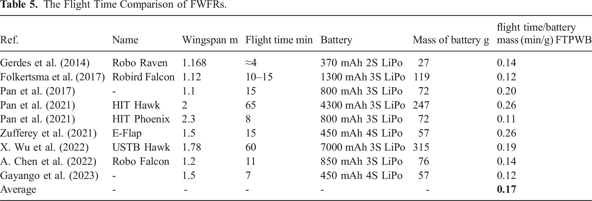
The size of the battery, the weight, and the payload also change this flight time significantly. Adding payload might reduce the flight time by
The flight range is linked to flight time, with only one difference: the communication range of the remote controller for the pilot, for the safety of the operation. In the case of manual flight, the flight range is limited to the range of the remote controller, reported 1 km in Sato et al. (2019) and 1.6 km in Gayango et al. (2023); please note that Gayango et al. (2023) reported both manual and autonomous flight. This range can be increased if the autonomous control is used with GPS positioning, subject to getting permission to fly without a pilot and manual remote control coverage as a safety feature.
4.3.2. Launching and landing
The primary way of launching a large-scale robotic bird is to start flapping and throwing the robot by hand to provide initial speed and sufficient height for the flight; this has been the frequent method for launching the systems, especially in outdoor experimentation (Gayango et al., 2023; Maldonado et al., 2020; Pan et al., 2021, etc.). While manual launching is easy, practical, and rational, providing automatic launching demonstrates other advantages, such as (1) obtaining similar initial flight conditions and (2) removing humans from the loop in case of having an automatic landing. The first mentioned point is also necessary for indoor experimentation when the flight area is limited space and repetition of flight is required for validation of control methods (Nekoo and Ollero, 2023) or applications (Scalvini et al., 2023; Zufferey et al., 2022).
Design and development of an FWFR launcher is relatively easy, while the landing/perching is more challenging. Linear guides with servo actuation, in addition to a customized holder, can be used to design a launcher (Zufferey et al., 2022). The initial speed of the launch was 4 m/s in the perching application. Perching on a branch is one of the most challenging “landing” methods for an FWFR, presented for the first time at the University of Seville (Zufferey et al., 2022). Before that, several methods presented “landing” using flapping-wing systems. One of the primary reports on perching on a surface was done in 2013 for large-scale FWFRs (Paranjape et al., 2013). Closed-loop control using wing actuation was presented for trajectory control without a rudder on the tail. Similar work using adaptive nonlinear control of a 1.5 m wingspan FWFR in gliding for landing was presented in Maldonado et al. (2020).
Going back to the landing subject, taking the bird by an operator is feasible and reported in the literature since the FWFRs are lightweight and safe for interaction with humans (Gayango et al., 2023). Landing on a net was also reported for indoor short flights, then the robot safely landed without impact to the ground when the trajectory of the robot is important in the limited space (Nekoo and Ollero, 2023). Launching, landing automatically, and taking off again pave the way toward completely autonomous FWFR without a human in the loop; the idea of performing several flights without interference from humans is an open research topic so far.
5. Control
5.1. Control approaches
Having command over the orientation and position of the robot directly increases functionality and provides stable flights and maneuvers for applications; hence, the controller design for flapping-wing systems is a necessary step in operation and can be categorized into: (1) Manual control. It refers to the conventional control of a pilot over the FWFRs using radio control (RC) for transmitting the command signals to the actuators. The minimum hardware components for the manual operation of a flapping-wing robot with an RC are flapping/tail actuators, an RC transmitter, a receiver, and a battery. The weight of the electronics with these minimum items depends on the selection of the actuators and the battery; however, automatic orientation control is not available for the pilot. The augmentation of an IMU for easier control over the robot requires the installation of a microcontroller or microcomputer for the computations. Manual control is common in many platforms since one of the safety features for flight is the supervision of a pilot on the flight trajectory and operation of the system. So, in addition to automatic control based on localization and feedback, that is, GPS, and Vicon, switching to manual flight is necessary to override the command of the automatic controller as a safety feature. (2) Open loop control. The application of open-loop control is frequent in flapping-wing systems to validate aerodynamics/dynamics terms and parameter identification. The method is to define a proper open-loop reference for the actuators to obtain a stable flight; the more is better for recording the motion and orientation of the robot. Then, the model and parameters can be validated based on the applied inputs and measured outputs. An example of a 2 s flight in an indoor testbed was presented for the validation of simplified dynamics for an FWFR (Sanchez-Laulhe et al., 2022). (3) Closed-loop control. The control loop can be designed by means of control techniques. Two methods exist: (a) Onboard computations and (b) Ground station communication with the robot. Onboard computation is more popular and frequent in the literature and requires a microcontroller, or preferably a microcomputer, installed on the robot bird. The processor must read the IMU/GPS feedback, compute the control actions using a control law, and generate pulse-width-modulation (PWM) signals. Those signals can be generated directly by microcontrollers; however, in the case of some microcomputers, such as Raspberry Pi boards, it is recommended to use PWM modules, such as PCA9685, to increase the number of ports for the output signals (Nekoo and Ollero, 2023). Linking microcontrollers (STM32) to microcomputers (Nano Pi NEO) was also reported to use them as PWM modules in addition to other tasks (Zufferey et al., 2022). The feedback to the robot can also be generated by a motion capture system (i.e., Optitrack or VICON). However, this will reduce the range of the flight to the range of visual localization of the robot. Communication with the robot is a helpful option when the weight of the microcomputer and the required battery cannot be implemented on the smaller FWFR with a small payload. Then, the computation of the controller and the visual feedback are done on a ground station, and only the input PWM signals are sent to the digital board on the robot. The list of applied closed-loop controllers and a brief survey will be presented in Subsection 5.5.
5.2. Control implementation
A general schematic representation of a closed-loop control block diagram is expressed in Figure 12. The feedback can be obtained through the positioning system (IMU, GPS, OptiTrack or Vicon motion capture system, ultra-wideband sensor, etc). The data must be continuous and noiseless and fed to the control unit. The controller commonly tries to reduce the error in orientation dynamics and also the position variables, especially height. There is a complex relation between the actuators and the generalized coordinates, with interaction within the generalized coordinates, that is, changing the pitch angle increases/decreases the height of the robot; an increase in flapping can also increase the height and forward speed. So, the relation between the output of the control unit in Figure 12 and the PWM signals of actuators is not easy to find. Therefore, a mixer matrix block is introduced, which includes the transformation between the control and PWM signals and also changes the scale of the signal from force/position to PWM digits. The PWM signals actuate the flapping wing motor (faster or slower) and command some corrections on the tails/rudder. The block diagram of a control, actuators, and dynamics of a flapping-wing system.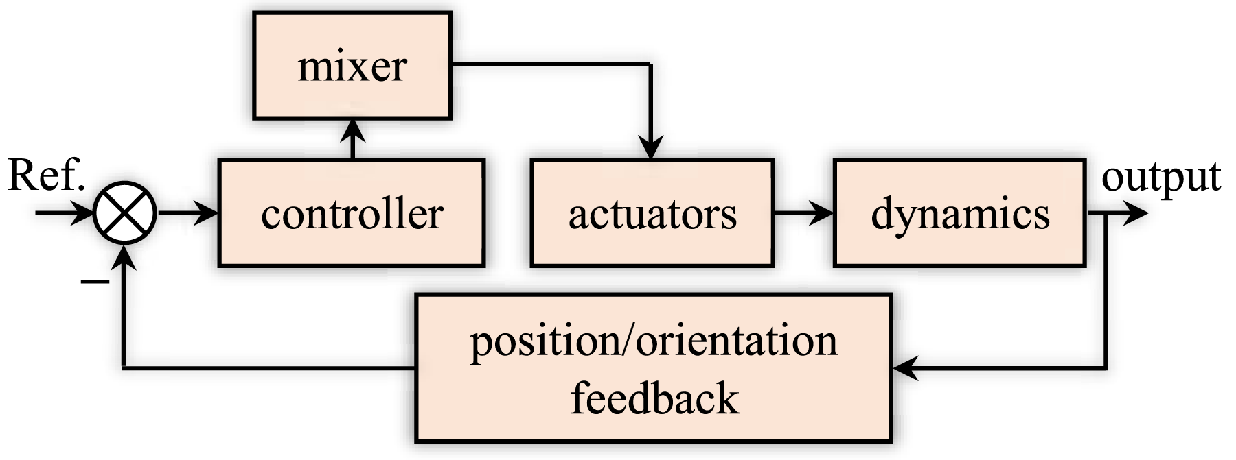
Moving toward bio-inspiration for robotic birds, the vertical rudder in the tail can be removed, and the rotation of the wings can compensate for the missing actuator; that method generates asymmetric lift force, which results in turning left or right (A. Chen et al., 2022; Folkertsma et al., 2017; Gerdes et al., 2014).
5.3. Actuations
The actuators of the flapping-wing robots are split into two parts: flapping and tail/wing control. The generation of flapping is commonly done by brushless direct current motors. The high-speed rotation is reduced through a set of reduction gears and then translated into a reciprocating motion through a crank or cam mechanism. The majority of the flapping actuation for large-scale birds uses brushless DC motors; however, rarely, servomotors were used to generate this action as well (Diez-de-los-Rios et al., 2021; Huang et al., 2022). Failure in high-speed flapping was a reported problem for servomotors as flapping actuators, which means the command is faster than the capacity of the servomotors to finish their flapping range. If one increases the flapping frequency a lot, the range of motion reduces significantly.
Servomotors are the best choices for tail/rudder actuation, considering the simplicity of implementation in control and mechatronics. The industry provides a significant variety of servomotors with different weights and torques. The torques for servomotors of the tail were reported as 3.2 kgcm (Nekoo and Ollero, 2023), 4.3 kgcm (Nekoo et al., 2022b), and 1.5 kgcm for RoboRaven (Gerdes et al., 2014), which normally result is less than 15 g weight. Servo-actuated tails provide a rigid control surface for the robot; however, alternative continuous actuation can be achieved using smart materials (Perez-Sanchez et al., 2021). Continuous actuation is a tendency toward bio-inspiration and gaining more control over the system, and it can be applied to the tip of the wings. A change in the tip of the wing can change the lift force of the wings, then change flight direction (Savastano et al., 2022).
5.4. Sensors
The installed sensors on an aerial robot present two functionalities: localization and positioning of the robot itself, and monitoring/data collection for an application. Here, in this subsection, the first type of sensor is studied, which helps the robot to fly and receive feedback on its orientation and position such as conventional IMUs, GPS, global navigation satellite system (GNSS), wind sensors, and environment perception (conventional RGB cameras, event cameras, other sensors).
The popular tools for positioning an FWFR are an IMU for orientation and a GPS for translation of the robot. While the precision of IMUs is satisfactory, the translation positioning systems provide data with an accuracy scale of meters, specifically height measurement. The GPS precision satisfied large trajectory tracking in outdoor maneuvers (A. Chen et al., 2022; Gayango et al., 2023; G. Liu et al., 2022; X. Wu et al., 2022); the total station is another method to generate more accurate feedback, but limited to up to 1.5 km distance (Rodriguez-Gomez et al., 2021). Hence, to use GPS and cover large distance trajectories and gain precision at least close to the end of trajectories (i.e., for applications such as landing/perching), visual perception can be used. Visual perception using an event camera was also applied to an FWFR for target detection (Eguiluz et al., 2021). The RGB cameras can serve for perception as well, though the disturbance of the flapping to the camera’s field of view disrupts the image processing significantly. This disturbance and negative effect on the visual system was amended using compensation mechanisms and a camera stabilizer (Pan et al., 2020).
Motion capture systems, that is, OptiTrack or Vicon trackers, are high-precision localization methods for position and orientation measurements. They are limited to closed-limited spaces covered by the arranged cameras, usually in an indoor testbed. The flapping-wing systems are indeed preferable in outdoor flights, though indoor testbeds offer advantages such as steady conditions for experimentation, especially wind, which significantly affects the flight performance and sometimes cancels the flight if that is severe. The validity of research, such as testing a controller or an application, needs repetition and steady conditions that motivate using motion tracking systems for indoor experimentation. Some examples are the implementation of a nonlinear control on a flapping-wing robot (Nekoo and Ollero, 2023), backward integration in optimal control (Nekoo and Ollero, 2024a), circular flight (Sanchez-Laulhe Cazorla et al., 2024), kinematic analysis (Rongfa et al., 2016), or a perching application (Zufferey et al., 2022), all demonstrated several datasets for validation of the approach.
The wind sensor is not related to the localization of the robot; however, it detects important information on the disturbance from the environment. While there are many works on insect-sized robots studying wind gusts, control, and disturbance rejection, this subject has not been studied sufficiently. The information on the wind, that is, the direction of the wind, will allow a user to fly the bird in the correct direction, benefit from a gliding state, and avoid crashing in turns.
5.5. Closed-loop control methods
To use model-based controllers, a dynamic model of the FWFR represented in state-space form should be utilized. The high-fidelity FWFR model (8) is highly nonlinear with cross-couplings between the main body and wing dynamics. It presents the most complete case, the body of the bird, and the articulated wing components with aerodynamic terms. Therefore, designing control systems for such models is quite a challenging task. Instead, simplified models are more practical and capture the dominant dynamics for control. Furthermore, since FWFRs are mainly used in non-acrobatic flight regimes, it is standard to locally represent the orientation using Euler angles, leading to the state space of this simplified models-for-control being 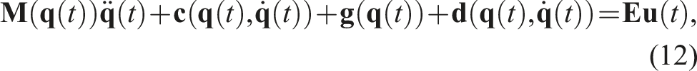
The state-vector of the system is set as 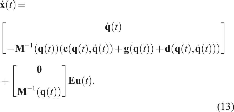
The dynamics (12) is an example, resulting from Section 2. This equation models the robot and, based on the necessity of the designer, can include more degrees of freedom and wing/tail components, and release a similar structure with bigger dimensions. Finally, the state-space representation will be produced as (13) to be used in control design algorithms. This example was made to show the link and connection between the dynamic structures in Section 2 and control designs in Section 5. This section applies the controllers based on the transformed dynamics in the following generic form that will be used for control:
The state-space dynamic (14) can represent different configurations, such as planar 2D models of the main body with height and pitch angle as generalized coordinates (n = 4 states in total), or 6-DoF modeling by considering 3D translation and Euler angles as generalized coordinates of the main-body (n = 12 states in total).
To develop controllers on nonlinear system (14) and solve the differential equation on simulations,
The number of actuators in the majority of modeled cases in the literature is limited to 3 inputs or, in some cases, 4. One of the inputs is flapping frequency, and the rest are blade actuation, either in the wings or tails. Then, the dynamics of a large-scale flapping wing are normally under-actuated since m < n/2. One consequence of under-actuation is a lack of control over all degrees of freedom, that is, hovering cannot be easily achieved by large robotic birds, even if some birds do in particular wind conditions (see Section 4.1). The assumption of the constant-velocity forward flight was usually made in modeling and control design.
The control input signals, u
i
(t) for i = 1, …, m, are gathered in 

The mixer matrix can be found using aerodynamics equations, CFD methods, etc. One example of a flapping system reported the mixer matrix using an experimental approach (Nekoo and Ollero, 2023). Then, the control law can be defined using linear methods for each motor using the well-known PD/PID u
i
(t) (Pan et al., 2020; X. Wu et al., 2022; Zufferey et al., 2022), or the LQR method in vector/matrix design
The PID controller does not need information on the system dynamics (16). The dynamics of subsystems such as pitch, yaw, or altitude can be modeled as
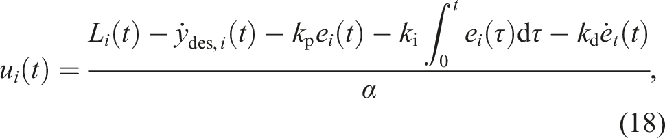
The dynamic of a subsystem (17) presents a limited model of the whole system (14) to enhance the performance of a pure PID. To enhance the contribution of the model in the control design, a linearized version of system (16) can be presented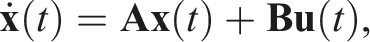
The PID input law does not have any limits and requires gain tuning to reach reasonable actuation and flights, the iPID (18) needs the convergence of subsystem dynamics (17), and finally, the LQR control law needs the controllability and observability of the matrices {
A control design was reported for a large-scale flapping-wing robot to benefit from the nonlinearity of the system (16) and present a sub-optimal policy using the state-dependent Riccati equation (Nekoo and Ollero, 2023). The nonlinear system is preserved by representing the system as a state-dependent coefficient (SDC) parameterization:
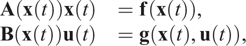
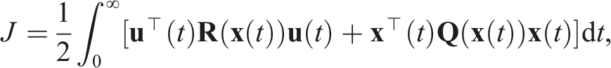
The observability condition states that the pair of {
Then, the control law of the SDRE can be used for the regulation or tracking of the system (Nekoo and Ollero, 2023):
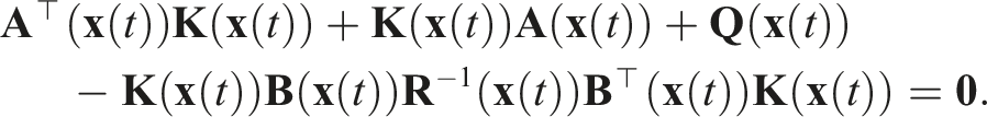
Comparing the control law of the SDRE (20) with the linear version of that, LQR, more contribution of the nonlinear terms inside the control law and control gain
6. Intelligent functionalities
Achieving intelligent functionalities with flapping-wing robots is a burgeoning but challenging research area. The research in this area faces three major challenges. First, flapping-wing robot designs are less mature than other types of flying robots, such as fixed-wing or quadrotor drones. The main consequence of this is that to work on intelligent functionalities, a research group needs to have expertise in flapping-wing robot design and control, and/or AI. This strongly limits the number of groups working on this topic. Second, compared to other types of flying robots of similar size, flapping-wing robots are typically lighter, with less payload capability. Especially for small or even insect-sized flapping-wing robots, the resource restrictions in terms of computational power and sensors become extreme as compared to typical flying robots. A flapping wing-robot such as the DelFly Nimble has a payload capability in the order of a few grams (e.g., 2.54 g in (Olejnik et al., 2020)) and an insect-sized flapping-wing robot even in the order of milligrams (e.g., 6 mg in (Fuller et al., 2022)). Consequently, there are few studies on the autonomous flight of flapping-wing robots involving external sensing and/or processing (e.g., with motion tracking systems for flight control of very light-weight 10-g flapping-wing robots (Hsiao et al., 2012; Ndoye et al., 2023)). For onboard sensing and processing, the severe resource restrictions require novel, highly parsimonious approaches to realizing intelligent functionalities. One consequence of this is a large focus on vision as a sensing modality since cameras should act as passive, energy-efficient, lightweight sensors. Third, the flapping wing motion has a substantial effect on sensor measurements. Most notable is that vision measurements are strongly affected by the flapping wing motion. For example, when using a standard rolling shutter camera, the flapping wing motion makes the images blurry and deforms the shapes of objects in view, as the last line in the image is recorded at a different point in the flapping cycle than the first line (G. C. De Croon et al., 2012). Active camera stabilization can be a solution to this problem. However, the required additional hardware has restricted its use to larger flapping-wing robots. For example, Pan et al. designed a three-DoF stabilizer for the vision system of a 2.3 m wingspan flapping-wing robot (Pan et al., 2020). The sliding mechanism for the translation compensation of the flapping reduced the vibration of the camera and increased the quality of the data. Another illustrative example is (X. Wu et al., 2022), in which a custom-made, 66-g stabilizer was implemented on a 1.78 m wingspan flapping-wing robot. An alternative solution is to use an event-based camera since it can capture visual data with extremely low latency in the order of microseconds. For instance, in (Eguiluz et al., 2019), a DAVIS 346 event camera was installed on a flapping-wing robot with onboard computation. Rodríguez-Gómez et al. presented a dataset on the perception of a flapping-wing robot (Rodriguez-Gomez et al., 2021). The data of event camera perception, IMU, and Leica MS50 total station were presented in these references. Dong et al. used the vision system for object localization for a bird-sized flapping-wing system (Dong et al., 2021). Currently, the relatively large size of commercial event-based cameras has limited their use to larger flapping-wing robots.
Besides these challenges, early flapping-wing robots had one advantage with respect to contemporary quadrotor robots: their tails provided passive attitude stability. This meant that early on, research on flapping-wing robots could skip work on attitude control and focus on higher-level tasks such as visual servoing (Baek et al., 2011), height control (G. De Croon et al., 2009), and obstacle avoidance (G. C. De Croon et al., 2011). It must be noted that intelligent functionalities are not limited to vision-based systems; tactile sensing is a powerful tool for sensing the environment, especially for microflappers (Tu et al., 2019). High-frequency microflappers usually will not lose the stability of flight when touching an object. They bounce back slightly and retrieve the flight mode. This makes them an interesting perception method in addition to vision-based systems for autonomous systems.
Still, as one may expect, the above challenges have been limiting the level of flight autonomy of flapping-wing robots. In (Floreano and Wood, 2015), three levels were defined: (1) sensory-motor autonomy for capabilities such as controlling attitude, velocity or position, (2) reactive autonomy for avoiding obstacles, coordinating with other drones, taking off and landing, and (3) cognitive autonomy for skills such as navigating between relevant places in the environment, recognizing objects, and learning. Below, we will give examples of flapping-wing robots performing elements that belong to all three of these autonomy levels.
6.1. Visual servoing
Visual servoing is a fundamental robotic vision task that allows robots to make precise maneuvers with respect to a visual target. This skill is essential for observation missions or for moving to a given target, for example, as required for perching on a branch. An early example of visual servoing is to follow a paper trail on the ground using an onboard camera and external processing (G. De Croon et al., 2009). The first onboard example of visual servoing was presented in (Baek et al., 2011) and involved a 13 g ornithopter equipped with a Wii-mote infrared camera.
The maneuverability of flapping-wing robots plays an important role in visual servoing. The main problem is the missing visual features being tracked due to the pattern leaving the camera’s field of view because of the lack of maneuverability and the oscillation of the camera pointed out above.
Image-based visual servoing (IBVS) by tracking linear features was also implemented in the E-Flap (Eguiluz et al., 2021). When applying IBVS, the flapping-wing robot velocity commands are computed from the errors between the goal positions of the features 
The kinematics of the image feature can be expressed as
The IBVS is more difficult in flapping-wing systems than in multi-rotor systems because the compensation of the rotational motion by projecting the visual feature into a virtual frame (Eguiluz et al., 2020; Jabbari et al., 2014) has greater risks of missing the feature tracks. This rotational compensation, with flapping-wing robots, is subject to the constraints of the underactuated systems. Thus, for instance, the robot must tilt to control the altitude, and the roll and yaw rotations are coupled to control the lateral motion. Therefore, a compromise solution should guide the flapping-wing robot in translation while keeping the features within the camera’s field of view. This should be taken into account when computing the rotational part of the Jacobian
For tailless flapping-wing robots, maneuverability is less of a problem, as near hover, their behavior is similar to that of multi-rotors. In Olejnik et al. (2020), onboard visual servoing was applied to follow a line with the tailless DelFly Nimble. Line following was implemented with a rope having high contrast against the floor. The coordinates of the centroid of the line and the position and orientation of the line at some point in the lower half of the image were used as input to the control system, which generates yaw and roll commands. Subsampling methods were considered to accelerate image processing. Flight through circular gates was also achieved using a probabilistic Hough transform to compute the desired lateral and vertical position to drive the vehicle roll and thrust, respectively.
Finally, in order to deal with the flapping frequency and flight at higher speeds, in Eguiluz et al. (2021), an event-based camera was used for navigation, guidance, and control of the FWFR robot. The vision system detected a triangular shape as the target, and the controller regulated the bird toward the final point by using visual servoing.
6.2. Autonomous landing and perching
Perhaps the most popular way of launching and perching FWFRs so far has been manual throwing and grasping the bird by a human operator, thanks to the safety and lightweight characteristics of the robot. Though moving toward autonomy, removing the human from the loop, and landing/perching have been highlighted in the recent literature. Visual servoing is one of the needed ingredients to allow flapping-wing robots to perch. Perching is a very important functionality to interact with people and the environment and perform applications such as static long-time observations, picking accurately small objects, such as a tiny branch or a leaf of a tree (Nekoo et al., 2022b; Nekoo et al., 2023), for sampling in environment conservation, and contact inspection of elevated pipes, power lines, and other structures difficult to reach for people in charge of inspection and maintenance. The autonomous recharging of batteries also relies on landing or perching. The accurate perching of flapping-wing robots, particularly large-scale systems, is difficult due to high-speed actuation and precise timing requirements. Furthermore, high-impact resistance is also needed. Notice that the oscillation of the flapping-wing motion is very relevant for accurate perching, making it much more difficult than for fixed-wing and multi-rotor systems.
Bioinspired perching on a branch is performed by grasping using a suitable claw. Claw-shaped perching mechanisms for fixed-wing were presented in W. Stewart et al. (2022). Multi-rotor perching with a claw was presented in Broers and Armanini (2022) and Roderick et al. (2021), where the multirotor provided stable flight conditions for a bio-inspired leg to demonstrate the perching capability of the system.
The first autonomous large-scale flapping-wing robot perching on a branch was presented by the GRVC team
5
(Zufferey et al., 2022). The flapping-wing robot was controlled in pitch-yaw-altitude. A leg-claw system implemented a close-range correction with a bistable claw appendage design that could grasp a branch within 25 milliseconds and reopen. The system was validated with an evolution of the E-flap prototype (Zufferey et al., 2021) with a 700 g robot in total (520 g without the perching appendage) and replicated with a second robot, presented in Figure 13. The success rate of the perching and experiments was reported at 66% (Zufferey et al., 2021), and it increased by improvement and modifications to 88.3% (Nekoo et al., 2024). This claw is powerful and can maintain the body fixed after perching, but it is unsuitable for human interaction. In (Gomez-Tamm et al., 2020), a bio-inspired soft claw was presented for flapping-wing robots, considering the lightweight design and using shape memory alloy (SMA) actuators. Later, it was controlled using an SMA legs/claw mechanism with a state-dependent differential Riccati equation control strategy, taking into account the SMA dynamic behavior (position and temperature) and the actuator saturation (Perez-Sanchez et al., 2023). The perching of E-Flap on a rigid branch in the indoor testbed of the GRVC group, University of Seville. The video of the perching demonstration in September 2023: video.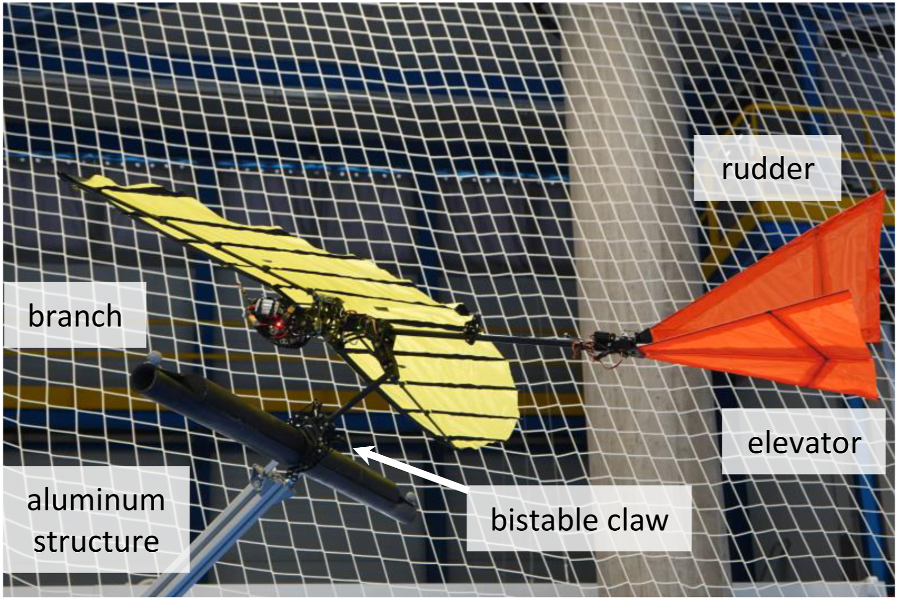
Although most research on perching has involved larger flapping wings able to carry claws, perching is also important to smaller flapping-wing drones. In Graule (2016), the perching of the centimeter-scale and 100 mg Robobee was presented. This perching was executed under a flat ceiling, leveraging electrostatic adhesion.
6.3. Obstacle avoidance
Even though soft-flapping-wing robots typically deal well with collisions, it remains important to avoid both static and dynamic obstacles. This represents a higher level of autonomy, as the visual appearance of obstacles varies substantially over different environments.
Much of the earlier research on autonomous flapping wing flight predominantly focused on the avoidance of static obstacles. Optical flow is an important monocular vision cue for insects and has been investigated for obstacle avoidance on rotorcraft (Franceschini et al., 2009; Serres and Ruffier, 2017). As optical flow calculations can be done in computationally efficient ways, it was also a prime candidate for use on flapping-wing robots (Bermudez and Fearing, 2009; Duhamel et al., 2012). However, due to the flapping wing motion, rotational optical flow dominates the translational optical flow. Consequently, it turned out to be very challenging to extract distance information from the flow. This led to alternative approaches, such as the use of an “appearance variation cue” (G. C. De Croon et al., 2011), the onboard machine learning of monocular distance cues (Lamers et al., 2016), or stereo vision (De Wagter et al., 2014; Tijmons et al., 2017) (Figure 14). Time-lapse of autonomous flight of flapping-wing robots. (a) Visual serving of the 13-g “i-Bird” using a “Wii-mote” sensor (Baek et al., 2011). (b) Autonomous indoor exploration of the 20-g “DelFly Explorer” using a 4-g stereo camera (De Wagter et al., 2014).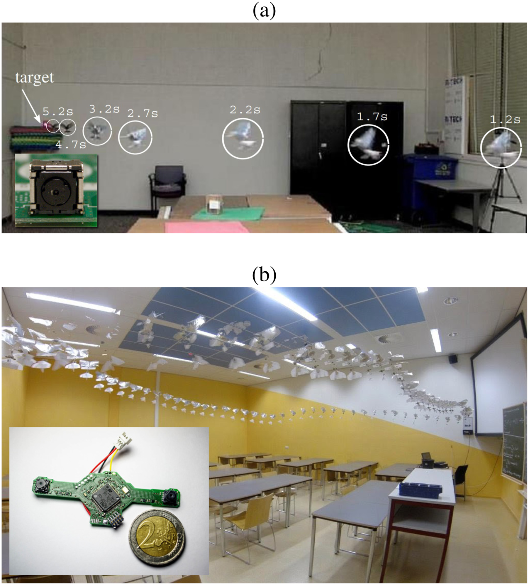
To date, the latter option of stereo vision has achieved the most robust results for onboard autonomous avoidance of static obstacles. The “DelFly Explorer” in De Wagter et al. (2014) and Tijmons et al. (2017) weighed 20 g, including a 4 g stereo vision system (cameras and STM32F04 processor). A main challenge was posed by the dynamics of the tailed flapping-wing robots with which the experiments were performed; it was not able to hover autonomously. Hence, a specific obstacle avoidance strategy was designed that circled in front of any obstacle within the visible field of view. This allowed the flapping-wing robot to avoid any obstacle while looking for a new flight direction. Later, the onboard algorithms were extended to achieve autonomous, multi-room exploration. The robot moved from one room to another and passed through the doors (Scheper et al., 2018). Specifically, the onboard stereo vision algorithm was to this end, complemented with a monocular “Snake-Gate” algorithm to locate doors.
Work on the avoidance of dynamic obstacles is more recent. The fully autonomous FWFR flight in Rodriguez-Gomez et al. (2022) used a fully onboard system with an event camera, which triggered pixel information due to changes of illumination in the scene, such as those produced by dynamic objects, and performed event-by-event processing to detect obstacles and evaluate possible collisions with the robot body. The onboard controller actuates over the horizontal and vertical tail deflections to execute the avoidance maneuver. The scheme was validated in both indoor and outdoor scenarios using obstacles of different shapes and sizes. Figure 15 illustrates the method. The success rate in dynamic obstacle avoidance was reported at 89.7%. The event-by-event processing nature and efficient implementation allowed fast onboard computation even in low processing capacity hardware, providing high rate estimations (250 Hz in the reported experiments). Sense and avoid scheme (top), and experiment (bottom).
6.4. Autonomous navigation
The described capabilities in Subsection 6.3 could allow the flapping-wing robots to explore unknown environments. However, for many real-world applications, the robots will have to be able to autonomously navigate to relevant places in the environment. In outdoor environments, for this purpose, GPS can be used (Bruck and Gupta, 2023; Roberts et al., 2014). For GPS-denied environments, other solutions have to be employed. One option is to install external infrastructure such as wireless beacons in order to form an indoor positioning system, for example, with ultra-wideband (Ledergerber et al., 2015). However, for many applications, installing external infrastructure is too expensive or simply impossible (e.g., think of search and rescue). In such cases, the robot will have to navigate using its onboard resources. The main approach to autonomous navigation is to employ simultaneous localization and mapping (SLAM) (Fuentes-Pacheco et al., 2015; Thrun, 2008). Subsequently, the robot can use the map to plan its path to different targets in the environment. However, a drawback of visual SLAM algorithms is that the involved algorithms are typically computationally expensive. Hence, for flapping-wing robots, alternatives are also of interest. For example, bug algorithms (K. N. McGuire et al., 2019; K. McGuire et al., 2019; Ng and Bräunl, 2007) were used for navigation by tiny,
7. Conclusions
7.1. Concluding remarks
Bio-inspired flapping-wing robots decrease the risks in interactions with humans/environment. This paper introduced their main properties by including thrust/lift generation, control, the tail’s role in maintaining stability, and wing morphing to increase maneuverability and flight endurance. Gliding and soaring using rising air currents, or the difference in wind speed between the ground and higher up (dynamic soaring), were discussed as means to increase flight endurance and range without energy consumption. This work presented dynamic and aerodynamic models that could be used to predict and plan the trajectories of the FWFR and track them. The dynamic system can be modeled as several interconnected subsystems: a rigid body and flexible wings. Aerodynamic models were also considered, discussing the limitations of adopting the linear conventional airflow models in fixed-wing vehicles. Existing approaches to dealing with the inherent complexity of flapping wings were reviewed in the paper. Furthermore, a port-Hamiltonian framework was presented to unify the treatment and bridge the gap between modeling, simulation, model-order reduction, and model-based control.
The paper reviewed the existing literature, classifying it into three main groups. The first group is insect-sized ones with mass
The inherent safety of flapping-wing robots, without propellers, provides advantages for many applications involving flights close to people or even in physical contact with them. One of these applications is monitoring and visual inspection, flying over infrastructures or in urban and industrial environments. Furthermore, the FWFR, in the gliding mode, can perform perfect sampling, that is, recording video of animals without disturbing them with noise, for a limited time (or more, depending on a favorable wind). The application of flapping-wing robots can open other applications, such as monitoring environmental conditions in populated industrial and urban areas, by including an air quality and noise sensor. The FWFR can also be applied to the inspection of infrastructures and industrial assets by including contact inspection after perching. Finally, the FWFRs are also useful for tiny object delivery to people, for example, in balconies or other urban and domestic infrastructures, and thus they could be used for last-mile delivery. We are convinced that the above applications will play a significant role in opening new research lines in aerial robotics.
7.2. Summary of the review
This work reviewed the flapping-wing robots, classifying them into three categories, and in each category, analyzes the important features of this technology in flight, control, and applications. The weight of the systems was highlighted as a restricting challenge in all categories of the FWFR, which limits the computational capacity of the robots. Despite this constraint in this line of technology, autonomous prototypes were demonstrated in trajectory tracking, online path planning, and obstacle avoidance, as reported in this paper.
7.3. The technology, design trend, and tangible insight
The design and technology of flapping-wing systems started with rudimentary platforms using small digital boards and customized wing and structure designs, then transitioned to microelectronics and customized on-structure installation of the electronic components; one example was reported in Zufferey et al. (2022). To move on and reach a big trend in the use of ornithopters, off-the-shelf particular boards and actuators must be developed to provoke the investments of the companies. Different potential applications (as business cases) are the use of FWFRs in monitoring, inspection, and interaction with humans. Low technology-readiness-level (TRL) prototypes showed successful missions in the mentioned areas, but FWFRs as products in the market are still missing.
Moreover, for reaching the full potential in economic and societal applications, FWFRs will have to operate as autonomously as possible. This not only implies that the robots have to fly and navigate, but also avoid obstacles. The FWFRs will also need to perform missions for extended times and recharge. Extending the autonomy capabilities of FWFRs will not only derive from advances in sensing and AI but also from enriching the body and available actuation. For example, providing FWFRs with robotic legs for walking and jumping capability can reduce the pressure on highly precise landings, extend operation time, allow for self-righting maneuvers after a fall, and make takeoffs possible in more locations (cf. C. Wu et al., 2024). We expect that the interaction between robotic advances and real-world applications will lead to further innovations that will make flapping-wing flying robots more mature as a technology—surpassing traditional flying robot designs in specific application areas.
Footnotes
Declaration of Conflicting Interests
The author(s) declared no potential conflicts of interest with respect to the research, authorship, and/or publication of this article.
Funding
The author(s) disclosed receipt of the following financial support for the research, authorship, and/or publication of this article: The authors acknowledge support from the HORIZON EUROPE European Research Council, Advanced Grant of the European Research Council GRIFFIN, Action 788247; The Advanced Grant of the European Research Council PortWings, Action 787675; The European ROBotics and AI Network (euROBIN, Grant agreement ID: 101070596), and The European Commission’s Marie Skłodowska-Curie Action (MSCA) Project RAICAM (GA101072634) 2024.