
Abstract
Unified force-impedance control (UFIC) aims at integrating the advantages of impedance control and force control. Compliance and exact force regulation are equally important abilities in modern robot manipulation. The developed passivity-based framework builds on the energy tank concept and is suitable for serial rigid and flexible-joint robots. Furthermore, it is able to deal either with direct force measurements or model-based contact force estimation. Thus, in this theoretical framework, the most relevant practical systems are covered and shown to be stable for arbitrary passive environments. Particular focus is also laid on a robust impedance-based contact/non-contact stabilization methodology that prevents abrupt, unwanted, and potentially dangerous movements of the manipulator in case of contact loss, a well-known problem of both impedance and force control. The validity of the approach is shown in simulation and through various experiments. Our work roots in Haddadin (2015); Schindlbeck and Haddadin (2015), where the basic UFIC regulation controller was proposed. In the present paper, we significantly advance this idea into a complete theoretical UFIC tracking framework, including rigorous stability analysis and extensive experimental evidence.
1. Introduction
The ability to physically interact with the environment is fundamental in today’s robot design. Position-controlled robots were not capable of doing so because they could not provide the necessary compliance for physical contacts, let alone the ability to track a desired wrench profile. As a result, over the past decades, continuous progress has been made in both hardware and software design to enable reliable force and motion control suitable for contact/non-contact scenarios. One of the most significant advancements came with the introduction of impedance control in Hogan (1985), enabling torque-controlled robots not only to follow desired trajectories in free space but also to establish and shape desired interaction behaviors when in physical contact. Additionally, if the task is to regulate the interaction wrench, one approach is to shape the impedance or the desired trajectory based on the sensed wrench, known as Indirect Force Control (Salisbury, 1980; Whitney, 1977; Lutscher et al., 2017). Yet, to avoid energy over-accumulation in the motion controller’s compliance, the Direct Force Control approach, where the robot’s input torque is directly linked to the wrench error, can be used (Eppinger and Seering, 1987; Zeng and Hemami, 1997; Villani and Schutter, 2016). The similarity and distinction between these two approaches are highlighted in Volpe and Khosla (1995) and Won et al. (1997), respectively.
As the diversity of tasks that a robot should perform autonomously increases, having a single interaction controller capable of controlling both motion and force can eliminate the need for constant controller switching and the associated instability issues (Whitney, 1987). Moreover, there are numerous manipulation tasks where force and motion must be controlled simultaneously, see Figure 1. Therefore, the development of simultaneous force-motion controllers has drawn considerable attention for a long time. Controlling the contact wrench at high performance over complex, discontinuous, and possibly compliant surfaces requires exact and robust force and compliant motion control.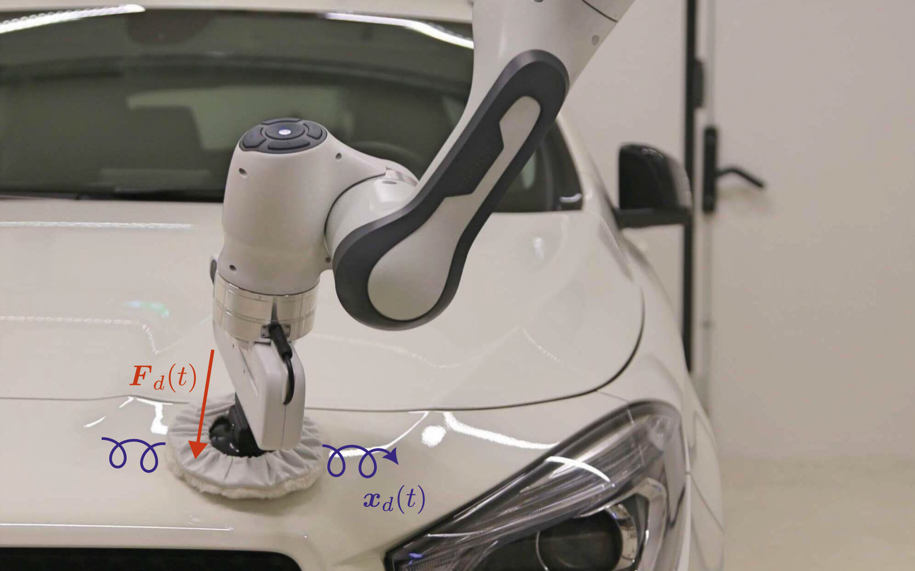
One of the most well-known approaches is the Hybrid Force-Motion control, initially introduced in Raibert and Craig (1981), where the output of a direct force control is superimposed onto the motion controller’s output. The approach was further improved in subsequent works. In Khatib and Burdick (1986) and Khatib (1987), the dynamics effects of the manipulator and the force sensor were incorporated into the motion control loop. The singularity-related instabilities of the motion control were tackled by incorporating the robot dynamics in Yoshikawa (1987), adjusting motion controller gains in An and Hollerbach (1987), and implementing nullspace controllers in Fisher and Mujtaba (1992). In Anderson and Spong (1988), an impedance controller was employed in the motion control loop. This was the case also for more recent works (Bodie et al., 2020; Brunner et al., 2022) for fully actuated aerial vehicles. Moreover, in Su et al. (1992), the robot’s desired motion was defined in the joint space. Finally, another common approach is based on the use of indirect force control, known as the External Force Feedback Loop approach (Hirzinger, 1983; De Schutter and Van Brussel, 1988; Almeida et al., 1999; Lopes and Almeida, 2008). In this method, the force is regulated in an outer loop, and its output is added to the input of the inner loop motion controller.
Irrespective of the specific controller used, a fundamental restriction exists in simultaneously regulating force and motion: it is generally not possible to control both in the same direction (Hogan, 1985). This limitation led to the incorporation of the Selection matrices 1 right from the earliest attempts in simultaneous force-motion control designs. The selection matrix ensures that the force and motion control tasks are performed in orthogonal (reciprocal) spaces. Typically, force control is applied in the direction of the environment constraints, while motion is controlled in unconstrained directions (Mason, 1981).
Using a selection matrix introduces some inherent issues. Firstly, as elaborated in Duffy (1990), concerns arise during investigations of orthogonality, such as the choice of units and reference frames. Moreover, the selection matrix must be compatible with the constraints imposed by the environment, necessitating a precise model of the environment for its derivation. However, as stated in Paul (1987), one of the biggest challenges in force-motion control is the lack of a perfect environment constraint model. That is why another class of controllers, known as Parallel force-motion controllers, was introduced. These controllers relax the strict requirement for orthogonality by imposing higher priority on either the force or motion control task. Examples include Chiaverini et al. (1992); Chiaverini and Sciavicco (1993); Chiaverini et al. (1998); Siciliano (1996); De Schutter et al. (1998), where the force controller takes higher priority by incorporating an integrator part in the feedback loop. Such a policy is not always practical. Specifically, if the force controller takes over in an unconstrained direction (e.g., during a contact loss), the robot can accelerate, resulting in a hazardous situation. Similarly, if the motion controller takes higher priority in a constrained direction, significant penetration of the setpoint into the surface can lead to extreme contact wrenches. Hence, to avoid such unstable scenarios, it is crucial to incorporate a good enough environment model even in the parallel control policies.
There have been adaptive force-impedance control approaches aimed at addressing uncertainties in the environment model. One of the pioneering examples is West and Asada (1985), where the selection matrix continuously changes according to the newly imposed constraints. In Namvar and Aghili (2005), an adaptive hybrid controller is proposed, and the environment geometry is continuously estimated under certain assumptions, such as the maximum slope on the surface. In Doulgeri and Karayiannidis (2007); Karayiannidis and Doulgeri (2009), a soft hemispherical tip is assumed for the robot end-effector, and an adaptive term is introduced in the control input to handle uncertainties in the estimated surface normal direction. Other recent work on handling uncertainties in the environment model when using impedance control include Lin et al. (2021); Hathaway et al. (2023); Dyck et al. (2022).
Estimating the environmental constraints solely based on force and motion information is not always straightforward. A typical example involves confusing the surface friction force with a motion constraint. In such cases, not only should we refrain from stopping the motion control in the presence of friction, but we might also want to add a feed-forward force to the motion control output to compensate for the friction (Bona and Indri, 2005). A comprehensive study on the relationship between surface sliding motion and reactive frictional force is presented in Howe and Cutkosky (1996). Another challenge in such model-based approaches is that the environment model might be either complicated or dynamically changing. Therefore, estimating the environmental constraints might not be practical. As a result, rather than heavily relying on the estimated environment model to avoid the aforementioned instabilities, the force-motion control policy should be designed to be robust to possible model dependencies. This robustness ensures that the control approach remains effective even in the presence of uncertainties or variations in the environment.
1.1. Problem statement
In this paper, our aim is to develop a robust force-motion controller that avoids the instability issues associated with force control in unconstrained directions and motion control in constrained directions without requiring knowledge or estimation of a perfect environment model.
As motivated earlier, we will employ the direct force control method to gain explicit control over the interaction wrench. Additionally, to ensure effective interaction with unmodelled environments, we will leverage impedance control to regulate motion. The cornerstone of our approach to guarantee stability in simultaneous force and motion control is the concept of passivity. Passivity analysis offers a solution to tackle the aforementioned instabilities linked to force control during motion and motion control during contact.
The passivity-based control approach was initially introduced in Ortega and Spong (1989) within the context of adaptive control for robot manipulators. However, the concept of passivity dates back to the 1950s in the field of network analysis (Youla et al., 1959). Passivity-based control has found widespread application in robotics to ensure the stability of controllers. In Kanaoka and Yoshikawa (2003) and Hatanaka et al. (2015), systematic approaches for investigating the passivity of controlled systems are presented. One of the common applications of passivity-based approaches is teleoperation. For instance, in Secchi et al. (2006), passivity is employed to address position drift during remote motion control of a robot. Particularly when dealing with time delays, passivity analysis becomes a powerful tool to ensure stability (Yokokohji et al., 2000; Hannaford and Ryu, 2002; Franken et al., 2011; Franchi et al., 2012). Furthermore, passivity-based control is utilized in Chopra and Spong (2006); Secchi et al. (2012); Tognon et al. (2018) for collaborative multi-robot scenarios and in Ott et al. (2004); Albu-Schäffer et al. (2004); Ott et al. (2008) the stability analysis of the flexible-joint robots. Finally, in a scenario more closely aligned with our objective, in Siciliano and Villani (1996), the concept of passivity is employed to ensure force and motion regulation when interacting with elastically compliant surfaces, yet without addressing the contact-loss instability problem.
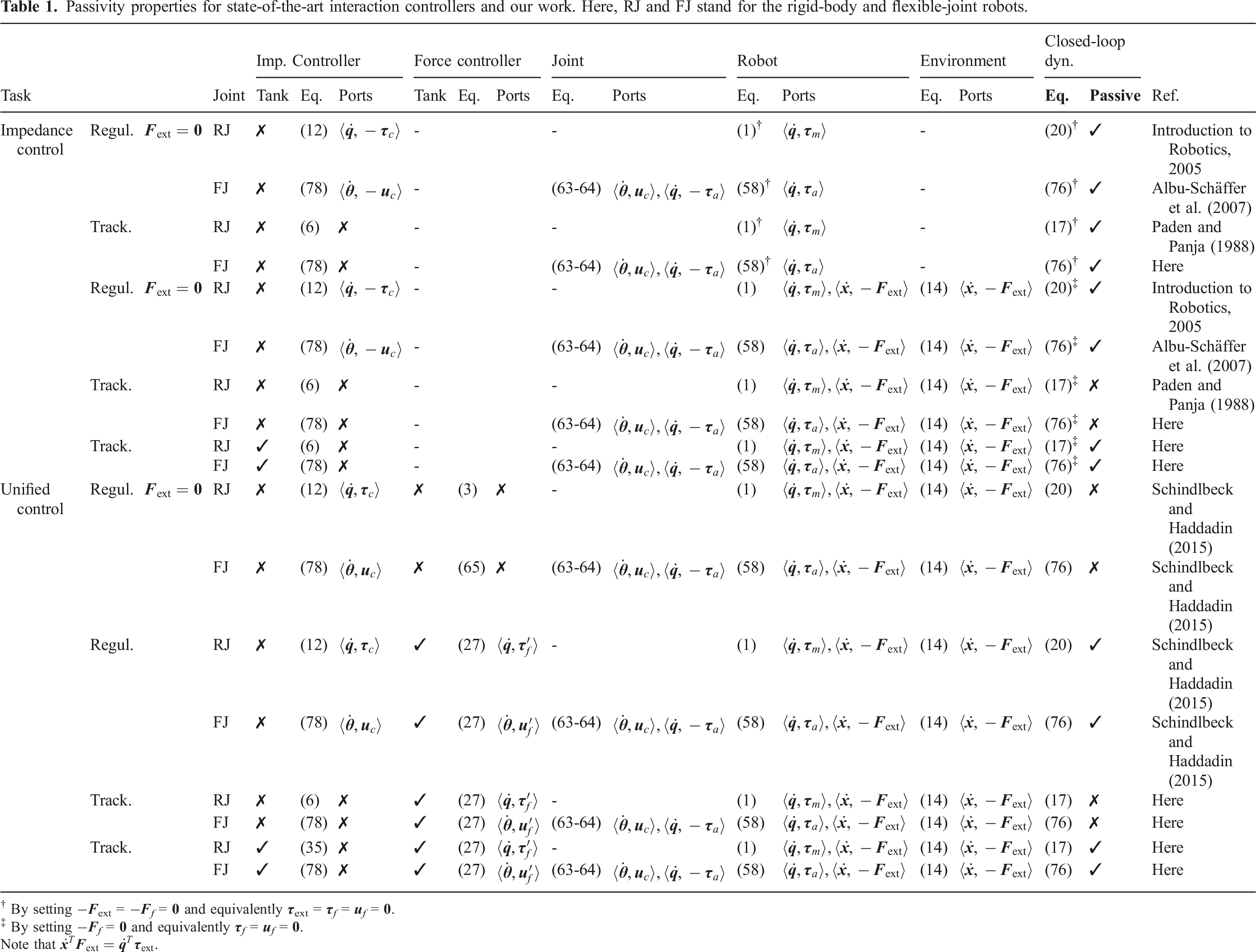
Passivity properties for state-of-the-art interaction controllers and our work. Here, RJ and FJ stand for the rigid-body and flexible-joint robots.
† By setting −
‡ By setting −
Note that
One of the first explicit use cases of virtual energy tanks was Secchi et al. (2006), where they preserved the passivity of scattering-based communication channels. The approach was also implicitly applied earlier in Secchi et al. (2006), using the so-called power continuous control terms to ensure stability. Over time, energy tanks gained popularity and found applications in different control design policies. In Franken et al. (2009), tanks were employed to stabilize teleoperation setups with discrete time-varying delays, and in Franken et al. (2011), an approach was presented to feed back the dissipated energy into the tank for a two-layered control architecture. Energy tanks have been widely utilized in various contexts, including the stabilization of cooperative multi-robot systems (Franchi et al., 2012; Secchi et al., 2012; Shahriari et al., 2022), time-varying impedance control (Ferraguti et al., 2013; Tadele et al., 2014; Kronander and Billard, 2016; Michel et al., 2020), trajectory modification in dynamic movement primitives (Shahriari et al., 2017), control of aerial vehicles (Rashad et al., 2019; Brunner et al., 2022), pneumatically actuated antagonistic joints (Toedtheide et al., 2017), controller switching policies (Ferraguti et al., 2015), and safety (Tadele et al., 2014; Lachner et al., 2021).
The energy tank augmentation approach serves as a method to control and limit energy generation from identified sources, which might otherwise result in unbounded energy production. Specifically, in our case, these sources are the force control action in the presence of non-orthogonal motion and the motion control action in the presence of non-orthogonal wrenches. By attaching tanks to each of these actions, we ensure that the generated energy remains bounded. A significant challenge in tank-based approaches lies in determining the initial energy of the tanks. Although, in our scenario, the environment model can assist in identifying the tank’s initial energy, we can still estimate the required initial energy even without this information. This estimation can be achieved by prioritizing control objectives based on their potential instabilities. In other words, we assess to what extent we allow potentially passivity-violating actions to perform their tasks. Consequently, many conventional limitations associated with simultaneous force-motion control designs can be mitigated. For instance, we can select arbitrary coordinates for each task and rely on the tank to ensure stability through its coordinate-free metric – energy. While our earlier work (Schindlbeck and Haddadin, 2015) introduced the basic concept, it focused on regulation tasks. The present study strives to offer a universal, all-encompassing solution to the challenge of simultaneous force and motion control, including the tracking case. To the best of the authors’ knowledge, this work represents the first systematic effort to unify impedance with force control under a single paradigm, overcoming the conventional limitations typically associated with such integration. We expanded our previous work to also encompass tracking tasks, which required the development of a dedicated energy tank for the impedance controller. Moreover, we devised a new control law and passivity analysis, taking into account the impact of joint flexibility when employing flexible-joint robots. Additionally, we made a concerted effort to provide a thorough elucidation of various aspects, with special emphasis on energy tank design and initialization strategies. As demonstrated in the experimental section, this approach significantly enhances practicality by minimizing the number of parameters that need tuning.
1.2. Contributions
The main contribution of this paper can be summarized as follows: 1. A stable controller capable of tracking wrench and/or motion without conventional requirements, such as space reciprocity or the need for an environment model. 2. Control design and stability proof for both rigid-body and flexible-joint robots. 3. Base-case virtual tank energy initialization strategy. 4. Systematic experimental analysis of performance, robustness, and accuracy using a seven degrees-of-freedom (DoFs) joint torque-controlled lightweight robot.
1.3. Structure
The remainder of the paper is organized as follows. Section 2 provides the fundamentals of rigid-body robot modeling and wrench sensing as a basis for the following theoretical concepts. Subsequently, Sec. 3 presents the Unified Force-Impedance Controller for rigid-body robots. Section 4 details a passivity analysis of the considered systems with virtual energy tank synthesis to guarantee the overall passivity. In Section 5, an approach for the initialization of the proposed energy tanks is outlined, followed by the contact-loss stabilization method based on coupling the impedance controller to the force controller in Sec. 6. Note that despite the focus of the paper is to a large extent on rigid robots and lightweight robots, 2 we also provide the theoretical framework for the flexible-joint case in the Appendix. This would also allow to apply UFIC to intrinsically elastic systems with constant joint viscoelasticity. For validating the theoretical framework, several challenging manipulation experiments are performed with the Franka Emika Robot (Haddadin et al., 2022) in Sec. 7. Finally, the paper concludes in Sec. 8.
2. Preliminaries
2.1. Notation
In this paper, we adopt the subsequent notation. The robot end-effector pose
2.2. Rigid-body robot model
The well-known dynamics of a second-order rigid-body robot model with n degrees-of-freedom are described by

3. Controller design
The control framework is developed in two steps. First, the primary force and impedance controllers are introduced in this section. Thereafter, in Sec. 4, the two energy tanks for the respective force and impedance controllers are deduced based on passivity analysis. Note that in the coming sections, we will focus on the rigid-body robots while the derivations for the flexible-joint robots can be found in the Appendix.
3.1. Cartesian force controller
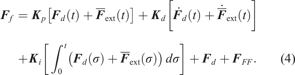
A direct PID force controller with a feedforward term can be designed in Cartesian space and mapped into joint space via the end-effector Jacobian matrix. For rigid robots the control law becomes

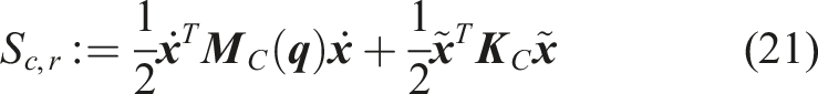
3.2. Rigid-body Cartesian impedance control
3.2.1. Tracking
It is well-known that in order to have a closed-loop Cartesian impedance behavior with the desired stiffness 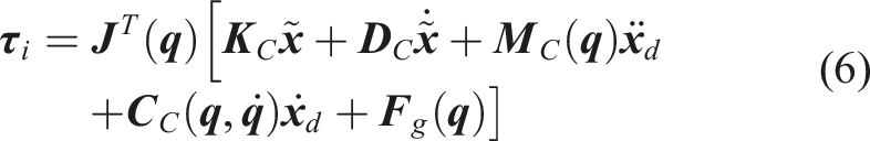


3.2.2. Regulation
In case the impedance desired pose is stationary 
For both cases,
3.3. Naive force-impedance controller
Summing (3) and (6) leads to a naive combined force-impedance controller
4. Stability analysis
4.1. Preliminary passivity analysis
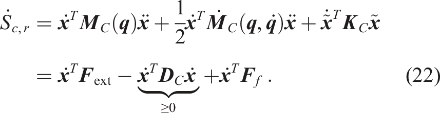
The first step of the passivity analysis is to perform a port-based decomposition of the closed-loop system, that is, a division into blocks that only communicate via their respective power variable pairs, namely, efforts and flows. The chosen blocks are the environment and the combined rigid-body dynamics with force-impedance controller. In the following, we analyze these blocks w.r.t. their passivity properties.
4.1.1. Environment
An important advantage of passivity-based control is that there is no need to exactly model the considered environment to prove stability except for assuming it to be passive. In other words, there is no restriction to specific types of environments, which on the other hand is typically assumed in stability proofs of force controllers (Wen and Murphy, 1990; Jung et al., 2004). In fact, it is sufficient to assume that the environment is passive w.r.t. the pair 
4.1.2. Force-impedance controlled rigid robot
4.1.2.1. Tracking
Considering (1), (8), (9), and (10), the dynamics model of the robot in the Cartesian becomes
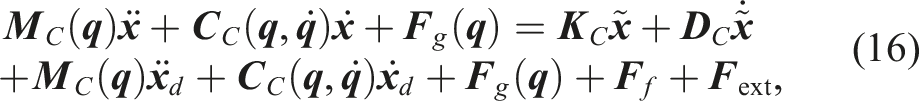
where the skew-symmetry of
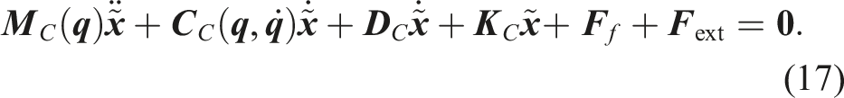
4.1.2.2. Regulation
For compliance control (12), the closed-loop dynamics (17) becomes
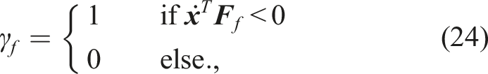
4.2. Tank augmentation: Force controller
In order to solve the problem of passivity violation, the concept of virtual energy tanks is applied. The subsequent concept and proof follow similar lines of thought as we proposed in Schindlbeck and Haddadin (2015) and Shahriari et al. (2018). First, we introduce the virtual energy tank for the force controller, that is, for the port 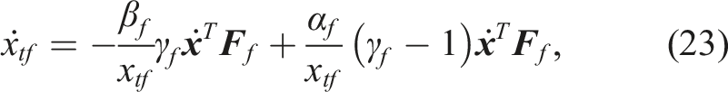


4.2.1. Note
The entire design of (23)-(28) could have been done also with
4.3. Tank augmentation: Impedance controller
Following the same approach as for the force controller, a second tank is defined for the port 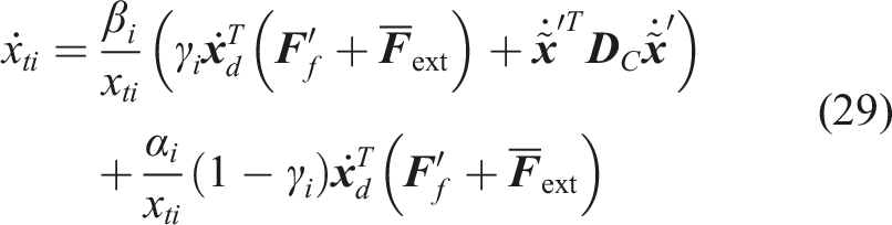


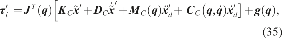
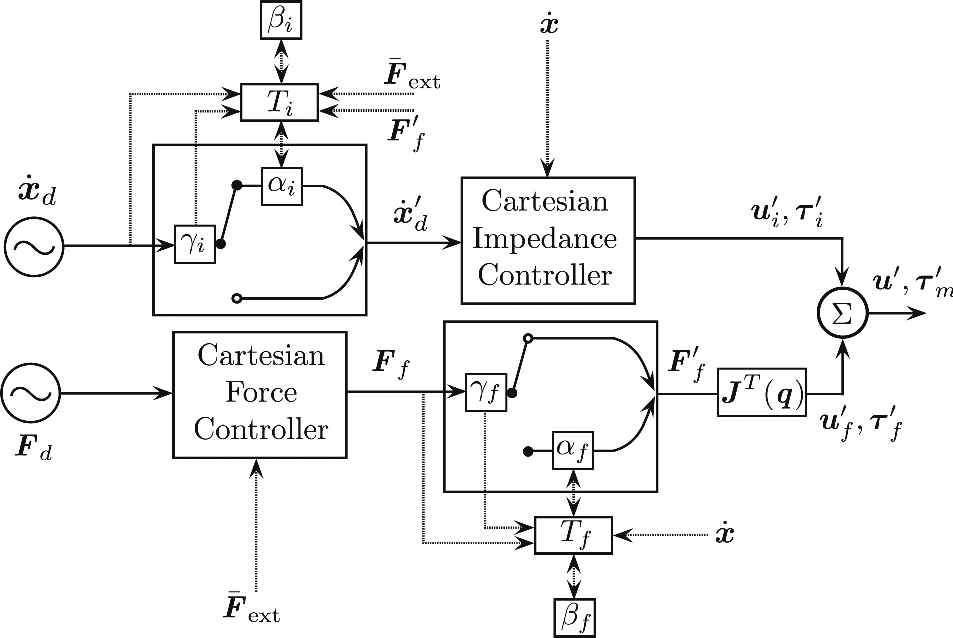
4.4. Final passivity-based force-impedance controller
Considering (27) and (35) the passivity-based Cartesian force-impedance controller for the rigid-body robot is Force and impedance tank architecture for UFIC.
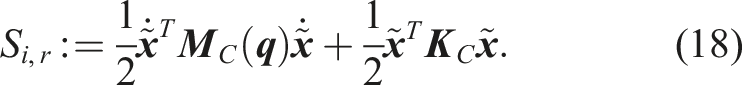
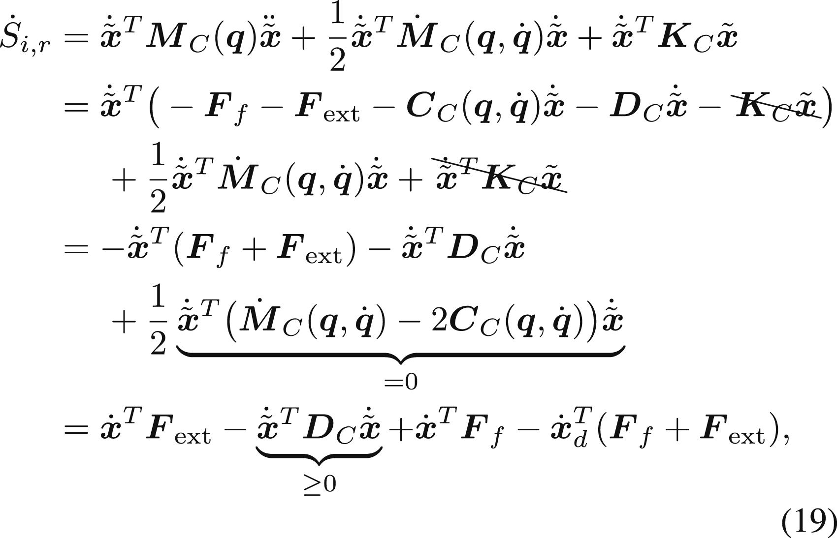
4.5. Passivity analysis after tank augmentation
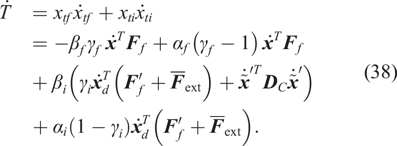
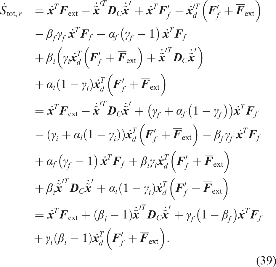
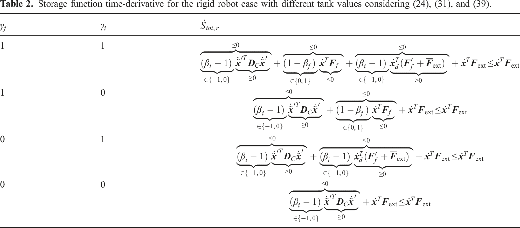
With the new controller design, the storage function for the whole system becomes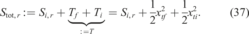
4.5.1. Note
Depending on the task, the desired wrench
4.6. Stability analysis via Lyapunov function
Let us define the overall system’s state variable to be: 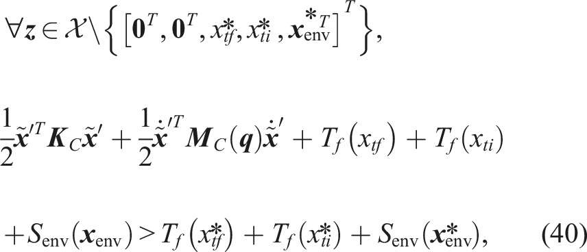
where 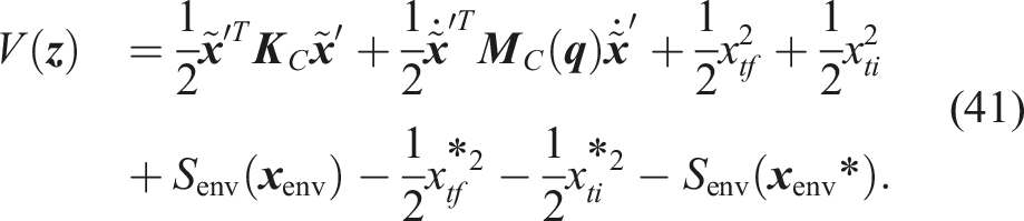
It can be seen that V (


The control objective achievement at 
4.6.1. Passivity cushion
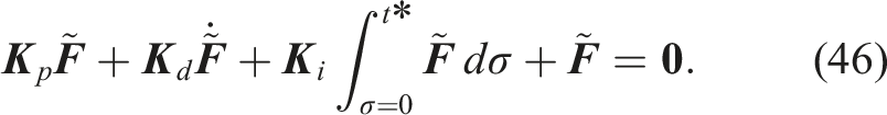
As long as the controller and tank as a combined system behave passive, the force controller (46) converges with its own dynamics to
4.6.2. Passivity violation
If the system of the controller within the passivity cushion behaves non-passive, it will be smoothly detached from the overall system not to violate the overall stability. In that case,
5. Controller initialization
Note that for the sake of clarity, the time dependency of the desired twists and wrenches are dropped. Furthermore, to maintain brevity, we have presented only one exemplar case for classes 1, 2A, and 2B among different coordinates.
By augmenting virtual energy tanks, the conventional rule that force and motion control need to belong exclusively to reciprocal spaces is overcome. However, two main problems remain when wrenches and velocities (twists) share non-orthogonal components.
First, achieving an arbitrary value for the interaction wrench and the motion in the same direction is generally not feasible (Hogan, 1984). Therefore, one of these objectives needs to be compromised to attain the other one or generally be chosen such that it is inherently consistent with the primary one due. This process can, for example, be accomplished by suitable controller parameterization to prioritize one control objective over the other.
Second, even after attaching the tanks, potentially passivity-violating actions, that is, force control in motion and motion control in contact may still occur. The extent of these actions depends on the amount of energy that can be provided by the tanks. Consequently, a design question arises: How much energy should the tanks reserve and provide?
Before addressing these two challenges, let us first examine the most relevant scenarios that may indeed lead to non-orthogonal forces and motions.
As explained earlier, a common approach for simultaneous control of force and motion is to control force in constrained directions while controlling motion in unconstrained directions. However, this necessitates online an exact geometrical model of the environment. As no model is free from errors and environmental changes, for example, due to the continuous interactions with the robot may lead to model discrepancies, the actual geometrical model is unlikely to match the coordinates in which the force and motion controllers are defined. Consequently, even though tasks are defined in reciprocal spaces, motions in the force control direction and wrenches in the motion control direction occur. Furthermore, even with a perfect geometric model of the environment, the dynamics of the environment may lead to non-orthogonal force and motion components. A classic example is surface friction. Even if motion control is specified in unconstrained directions, friction inherently induces process wrenches along the motion direction. Similarly, compliant surfaces lead to the generation of motion in the direction of the applied wrench. In the following, practical suggestions are presented to address these scenarios.
5.1. Task parametrization
To ensure that force control and impedance control function in reciprocal spaces, it is essential not only to define orthogonal desired motions and wrenches but also to properly set the associated controller parameters. Specifically, referring to (6), the elements of the stiffness and damping matrices
Subsequently, the force-impedance control tasks are categorized based on the kinematic constraints imposed by different surface classes as follows: • Class 1: Unconstrained point contact (e.g., filing, indentation, button pushing) • Class 2A: Unconstrained surface contact (e.g., screwing, polishing, or grinding a 2D surface) • Class 2B: Semi-constrained surface contact (e.g., polishing or grinding a 3D surface) • Class 2C: Constrained surface contact (e.g., docking maneuver) UFIC task variable configurations and contact reaction models.
Valid task variable combinations of the UFIC control inputs 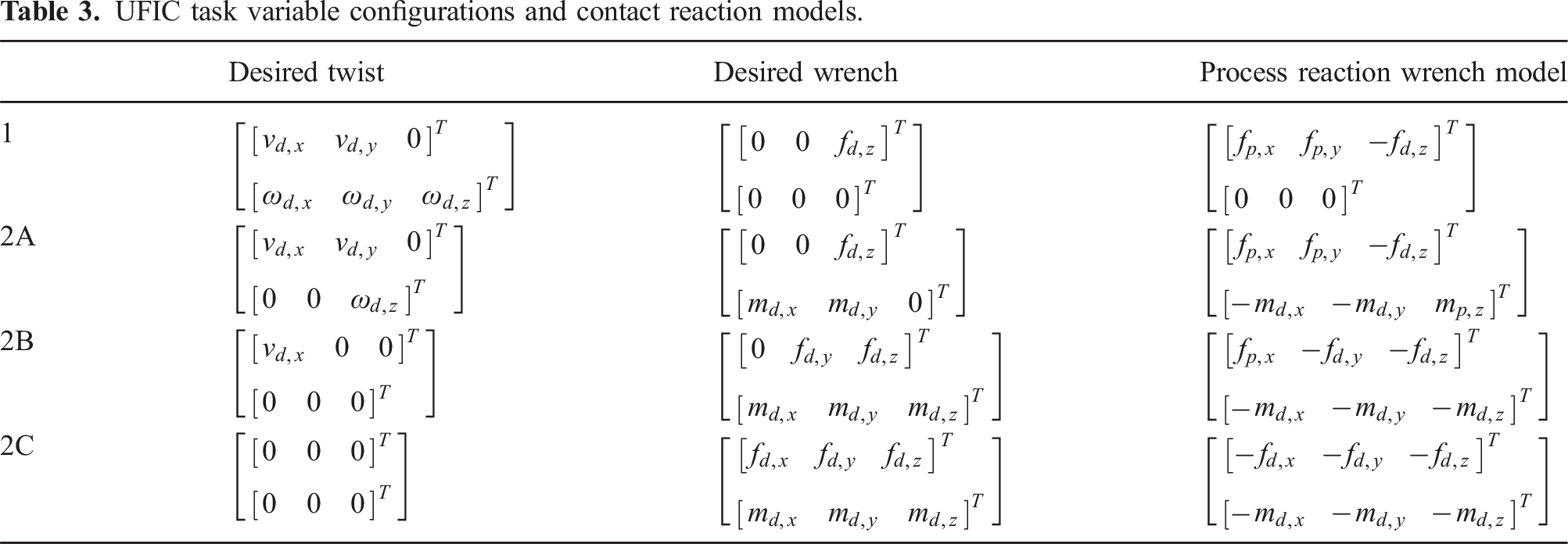
As explained earlier, a model discrepancy may lead to passivity violation even if the force and motion control tasks are designed to be reciprocal. Such discrepancy is not always unintentional. In certain cases, when the environment has a complex geometric shape, it may be more practical to employ a simplified model to construct the task coordinates. For instance, assuming a straight flat surface can be an appropriate approach when the surface curve is continuously changing. In this scenario, a practical approach is to increase the compliance of the impedance control, that is, decreasing the stiffness and damping values in directions where neither controlling force nor controlling motion is critical. By doing so, we allow the robot’s end-effector to adapt to the surface (see Sec. 7.4 for an example). In this case, it may be more sensible to define the force control task in the end-effector coordinates to ensure passive behavior. However, this approach can result in non-orthogonal force and motion control tasks if, due to the high compliance, the end-effector pose changes. To address such a situation, a suitable gain structure is to be implemented encoding whether force control or motion control should take precedence in a given direction. A common method involves prioritizing the force controller by using relatively higher values of the integrator feedback gain (Villani and Schutter, 2016).
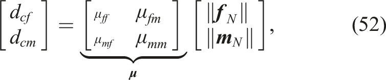
In addition to the environment kinematics model, the process dynamics characterized by friction, viscoelasticity, wearing behavior or even switching interaction dynamics have significant impacts. Such effects may be addressed through explicit consideration of the expected process wrenches, denoted as
5.2. Tank initialization
Even though stability is proven, this does not necessarily mean that the task can be fulfilled as desired. If any of the tanks is not loaded with a sufficient amount of energy, the force controller will be deactivated, or the impedance control will transition to compliance control. If this happens during manipulation, the intended task goal will not be achieved since the wrench cannot be regulated accordingly or the desired trajectory is not followed properly. To solve this problem, the concept of initial task energy E T was introduced in Haddadin (2015); Schindlbeck and Haddadin (2015). E T is defined as the minimal energy to be initially stored in the tanks for fulfilling all requirements of a manipulation task. This task energy or at least an estimated lower bound needs to be known prior to execution if not only stability but also correct task execution and performance are to be achieved. Obviously, the simplest strategy would be to use a practically high enough energy amount. However, since the provided energy is utilized for potentially passivity-violating actions, such as force control in motion and motion control in contact, prioritizing safety suggests avoiding overloading the tanks. Therefore, an approach should be pursued to estimate the minimum required initial energy for the virtual tanks. This estimation can be based on the task or the environment models. Alternatively, with the recent advances in machine learning, data-driven or model-informed hybrid approaches could be employed. For example, in Shahriari et al. (2019) and Benzi et al. (2022), two approaches are introduced for adapting the tank configurations, which prove especially useful in environments undergoing changes. In this study, we present a general base-case strategy for systematically initializing the energy tanks of the UFIC, laying the foundation for future learning-based initialization methods. In the following, we propose a few model-based approaches for the tank initialization process.
5.2.1. Force control tank
To determine how much energy is initially required in the force control tank to fulfill the task, let us first consider the scenarios where tank energy would be drained. As explained in Sec. 4.2, those scenarios occur as soon as the power
The robot accurately performs the desired linear force control task such that it is fully compensated by the surface reaction force and moment, that is, For simplicity, the environment is assumed to behave linearly elastic,
5
leading for this case with assumption 1 to Finally, another scenario where the force control tank can be drained is due to the feedforward term 

5.2.2. Impedance control tank
As discussed in Sec. 4.3, the power associated with the impedance control tank is the summation of powers
On the other hand, • disturbance 1: clamping due to unforeseen obstacles or faulty material • disturbance 2: jamming due to the surface friction or the dynamics effect of an object being carried
Disturbance 1 is clearly an unwanted fault and needs to be detected rather than coped with. Since it is directly related to the contact force, it is reasonable to assume that 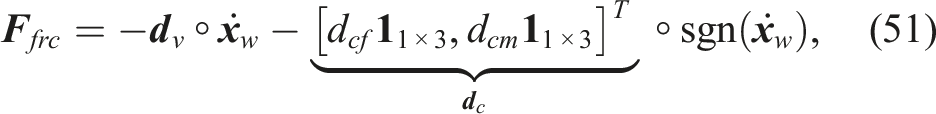
Because of assumption 1 it follows that
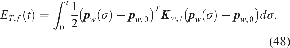
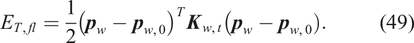
Because the robot accurately performs the motion tracking task for stationary contacts, we assume With these simple assumptions—essentially, they correspond to assuming the UFIC is correctly working—the estimated initial impedance tank energy becomes Obviously, the initial energy estimations (48) and (53) have to be tailored to the specific UFIC task at hand, that is, the surface class the robot is dealing with and the desired motion. Table 3 (last column) enumerates the process reaction wrenches according to the described estimation assumptions for all surface classes expressed in the local contact coordinates. The elements of the process wrench 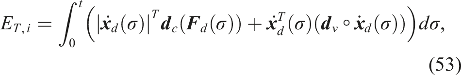
5.3. Effect of sensory errors on tank performance
So far, we have assumed access to accurate sensed or observed signals like
6. Contact-loss stabilization
A typical necessary, though not sufficient condition for contact loss is unwanted motions in force control directions. 7 Dealing with such behavior in the UFIC framework could in principle, be done with the energy tank design if, at the moment of contact loss, the remaining force control tank energy would be sufficiently low to cause a halt before a desired threshold travel distance. However, in reality, this is complex and impractical, given the many objectives the tank has to fulfill simultaneously and the fact everything needs to be designed in the energy domain.
Therefore, we employ a Supplemental state-based control policy alongside the derived energy tanks. This ensures that the energy in the force control tank is exclusively utilized according to the tank initialization procedure and handles abrupt contact-loss scenarios extremely well.
6.1. Controller shaping function
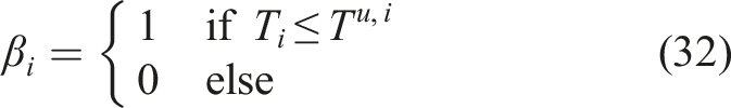
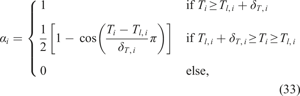
Our solution to the contact-loss problem centers around the basic principle of UFIC, namely, the full integration of impedance control and force control into a unified framework. Specifically, the underlying idea is as simple as it turns out to be effective: Valid contact corresponds to the Cartesian impedance deflection vector 
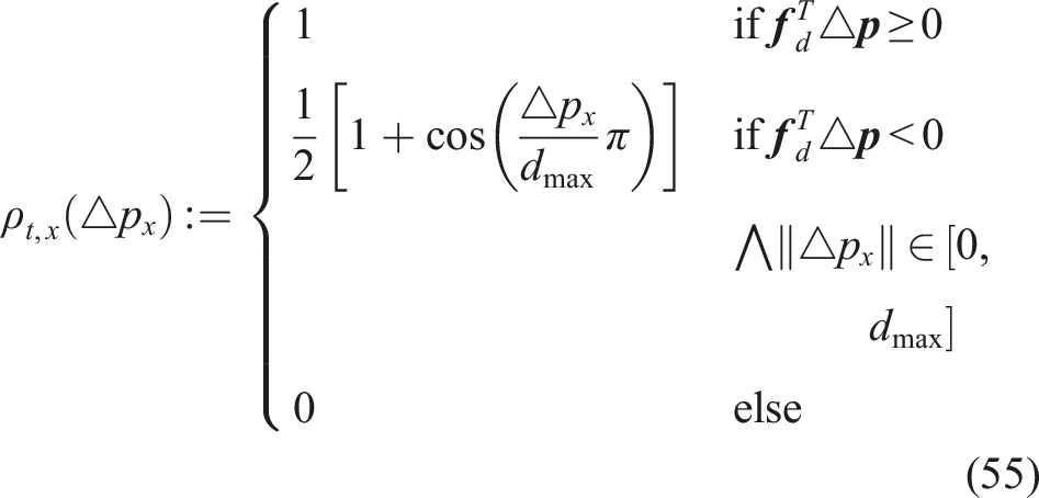
The shaping function ρt,x (△p
x
) for the translational case is constructed such that the force part of the controller is active when the desired force Left column: Impedance controlled robot with robustness region dmax for translation (upper) or ψmax for rotation (lower). Right column: Controller shaping function for the translational (upper) case and rotational case (lower).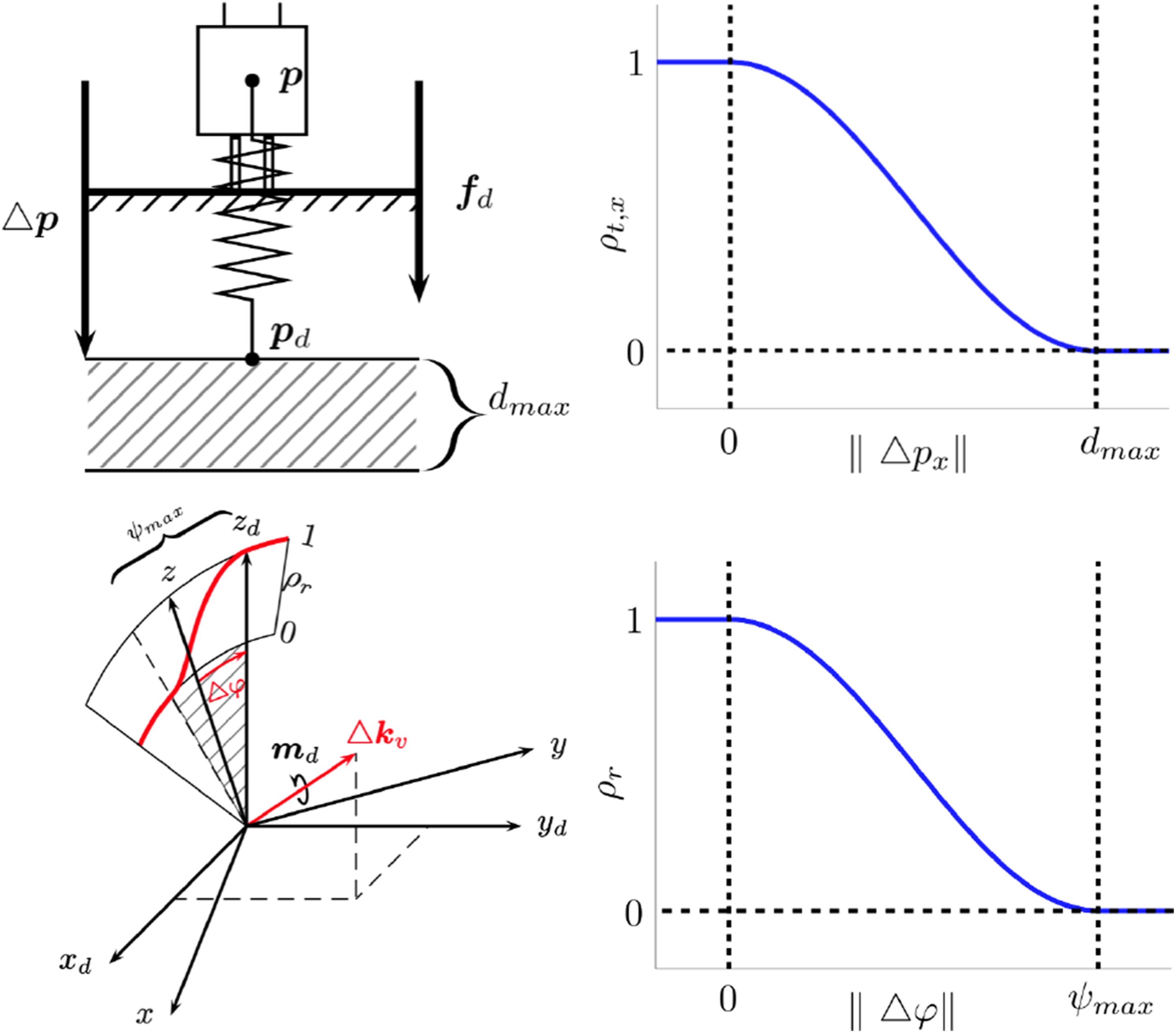
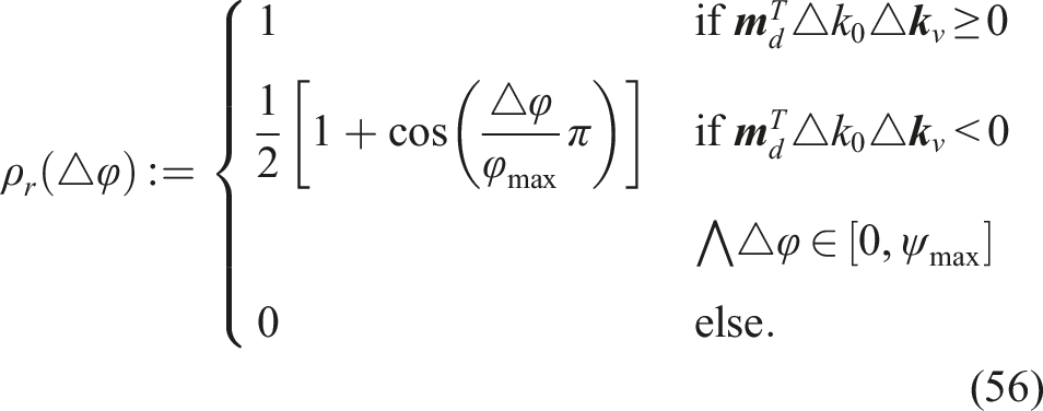
Similarly, the rotation controller shaping function ρ
r
(△φ) is constructed. To avoid singularities ρ
r
(△φ) is based on quaternions, see also Sec. 5. The rotation error is defined as △
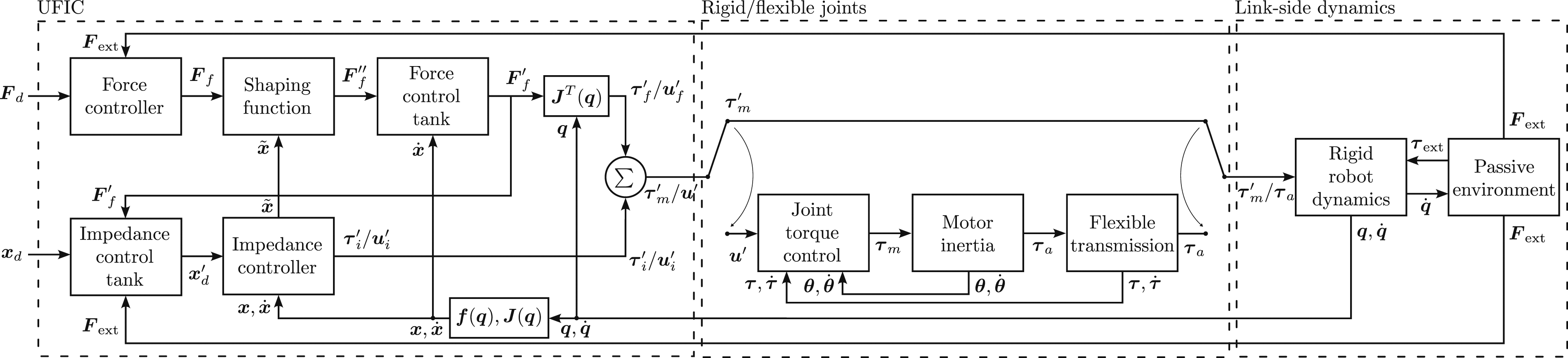
From a stability point of view, since the shaping function only scales the force controller part of the combined force-impedance controller, (28) can simply be redefined as Block diagram of the UFIC, robot system (rigid-body and flexible-joint), and passive environment.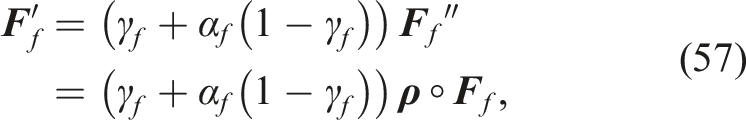
6.2. Discussion on soft-material
Overall, the proposed contact-loss shaping avoids abrupt and unsafe behavior by systematically coupling the advantages of force and impedance control. The robustness regions give the user also an intuitively interpretable design variable to shape the overall behavior of the task at hand.
Note that during tracking the desired force in contact with soft material, the robot might pass the impedance controller set point, although it is still in contact. As a result, the shaping function would decrease the effect of the force controller. This shows that not only the energy of the tank should be initialized and adapted, but also dmax and ψmax. The design and learning process obviously would need to properly reflect the rigidity and damping of the environment so that the shaping function does not unnecessarily stop the force controller before contact loss. This aspect, however, is beyond the current work and needs future analysis.
7. Experiments
For experimental validation, we conduct six experiments A-F with the Franka Emika robot (Haddadin et al., 2022). The built-in external force Experimental setups with Franka Emika Robot. Experimental gains and parameters.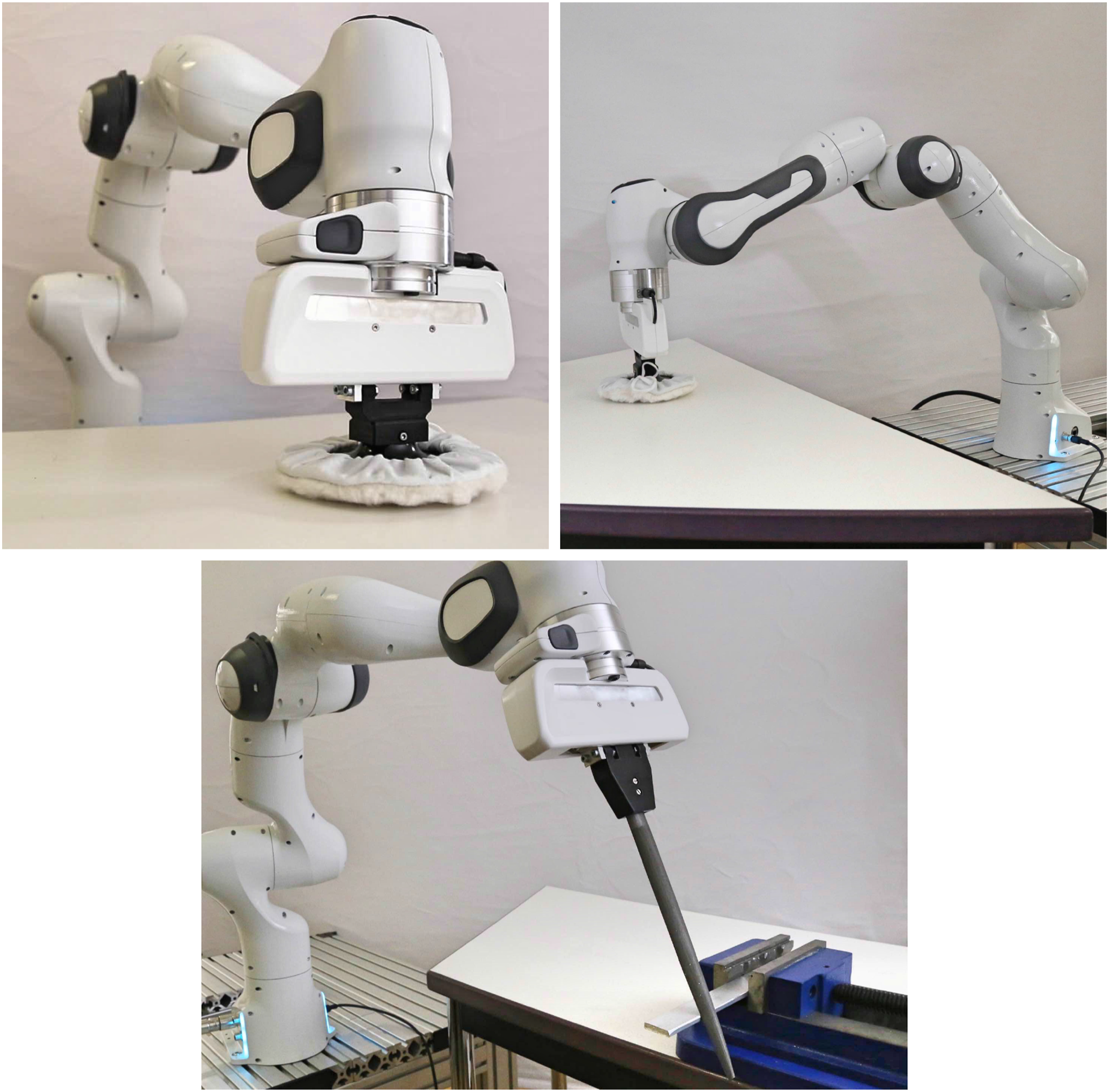
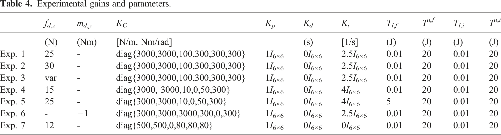
7.1. Experiment 1: Controlling contact and motion—polishing
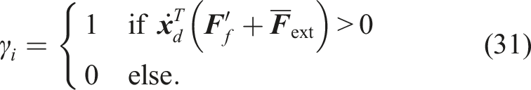
In the first experiment, the task is to control a normal force and execute orthogonal motion, exemplified by polishing a table. In Phase 1, contact is established via plain impedance control. Then, in Phase 2, UFIC control is activated to apply a specific desired force, and in Phase 3, circular motions on the table plane are commanded. Figure 6 depicts the force error in z-direction, the respective energies of the impedance control tank T
i
and force control tank T
f
, as well as x- and y-position of end-effector. Obviously, due to the low effective velocity in z-direction, the change in force control tank energy is negligible. Taking into account the tank dynamics (29), since the desired wrench and motion spaces are reciprocal, the force control output does not have an impact on the energy level of the impedance control tank. The remaining power values influencing the tank are Experiment 1: Force error, force, and impedance control tank energy and end-effector position for polishing task with different phases: Establishing contact (Phase 1), applying force (Phase 2), simultaneous polishing (Phase 3a), impedance control tank fill up (Phase 3b). Tank limits are indicated by green and red dotted lines.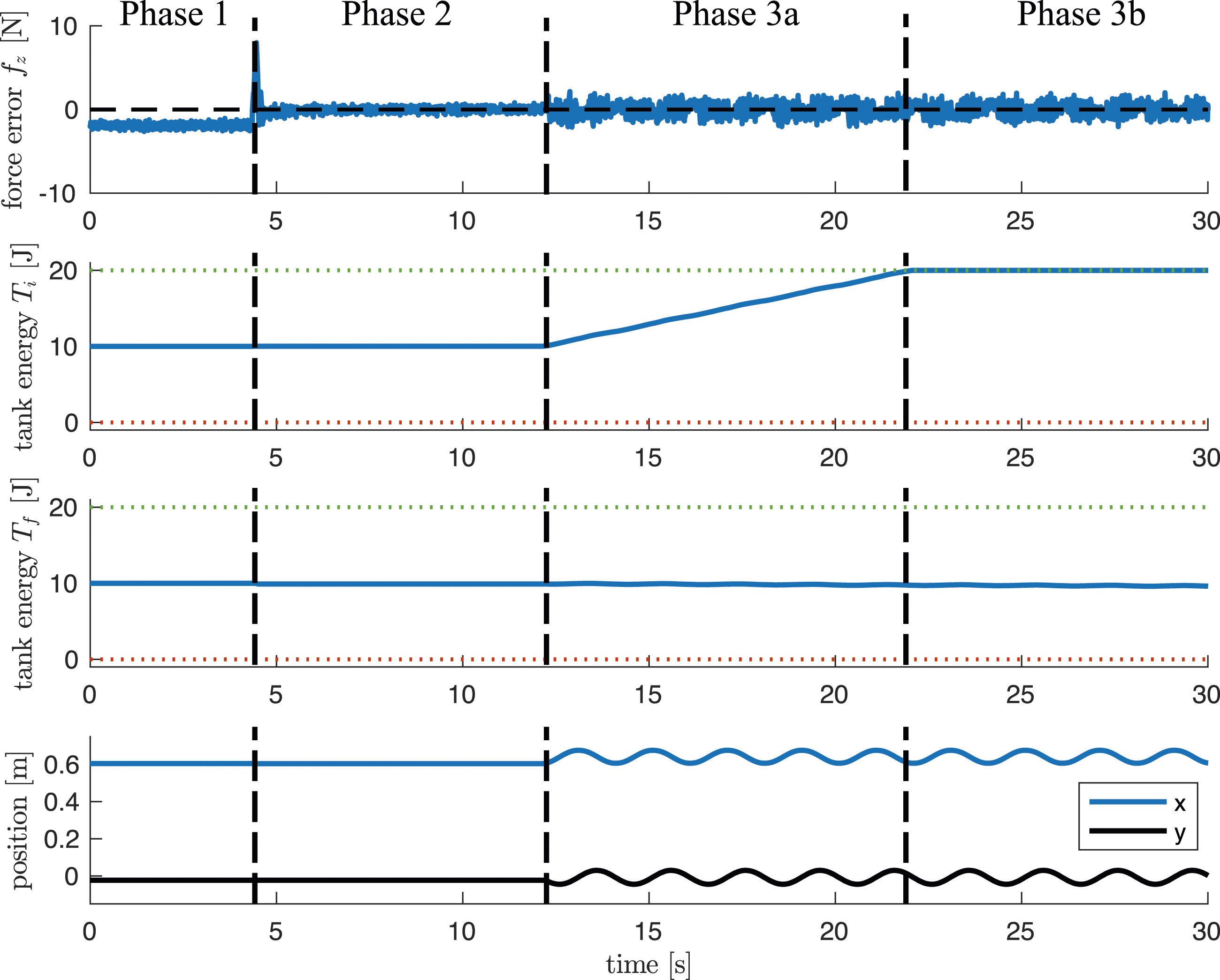
7.2. Experiment 2: Robustness—losing contact
To show how unexpected contact loss is handled as described in Sec. 6, the end-effector is placed on the table and in Phase A is controlled to apply the same desired force as in the previous experiment. Simultaneously, a constant velocity is commanded in x-direction, inducing a movement towards the edge of the table until contact is lost. Figure 7 depicts different phases of the experiment, and Figure 8 shows the force error, the energy level of the force control tank T
f
, shaping function ρt,z according to (55), and the end-effector position z. Experiment 2: Phases of contact-loss experiment. Experiment 2: Movement in x-direction (Phase A), movement beyond table edge (Phase B).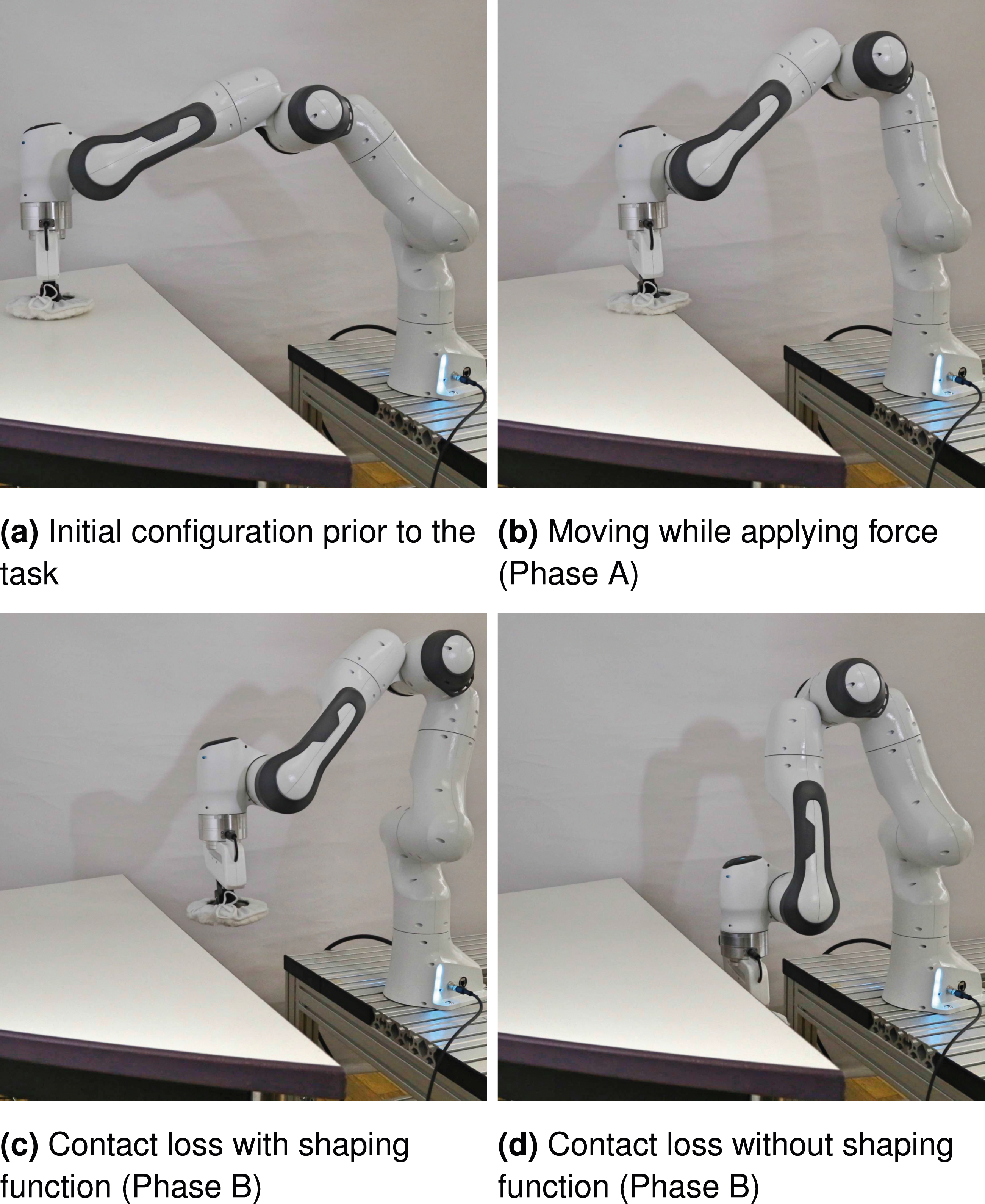
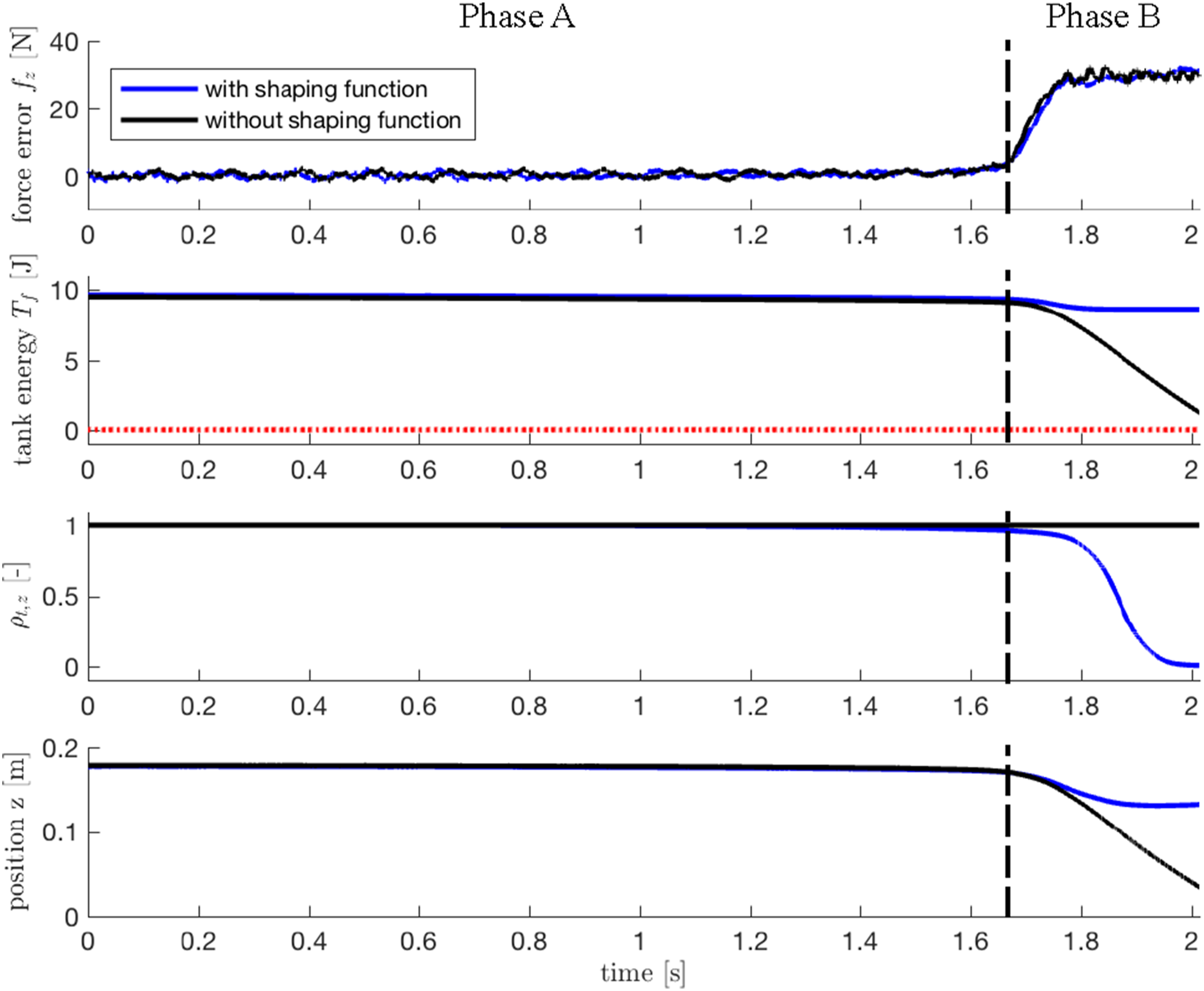
The experiment is done for two parameterizations. In the first case, the shaping function is activated with dmax = 0.05 m. As can be seen in Phase B immediately after the contact is lost, ρt,z smoothly decreases from 1 to 0. In turn, despite the force error ramps up to
7.3. Experiment 3: Force tracking—bandwidth
To experimentally evaluate the force tracking bandwidth, a sinusoidal wave with increasing frequency is used as a desired force while keeping the impedance controller’s setpoint constant. Figure 9 (upper) shows the tracking behavior for half a period of a sine wave at different frequencies. This time-domain plot is constructed from the concatenation of results from different experiments after some periods for each experiment. Figure 9 (lower) shows the mean absolute error measured for different frequencies with and without considering the phase lag. Even high tracking accuracy can be achieved up to 3.2 Hz. For higher frequencies beyond the mechanical system bandwidth, the phase lag starts causing significant tracking errors. Experiment 3: Force tracking performance at various frequencies, considering the time lag between the actual and desired values.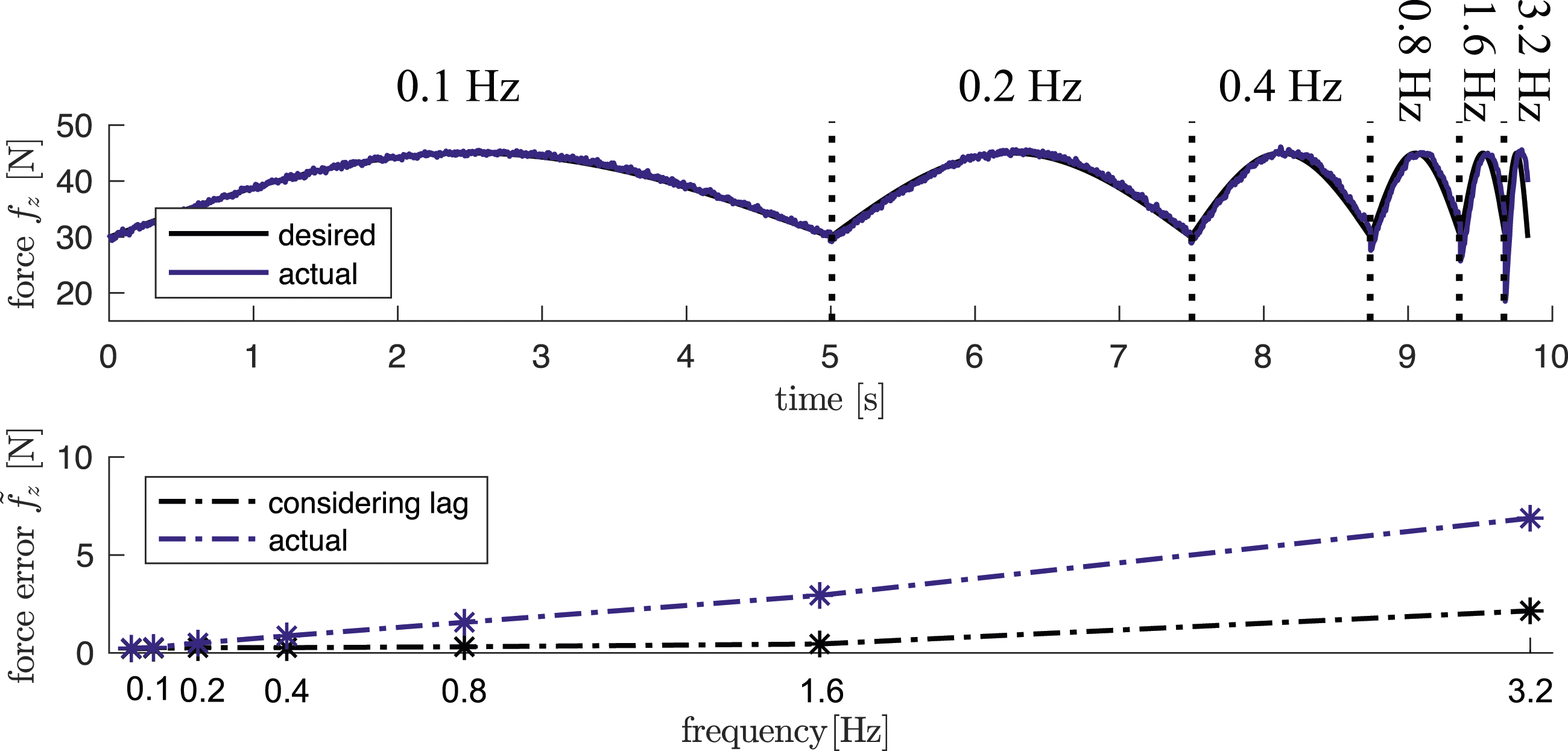
7.4. Experiment 4: Controlling contact and motion under heavy disturbance—aluminum seesaw
In order to show how a robot under UFIC control can robustly adapt to an unknown environment even under unexpected heavy disturbances and contact loss, a seesaw setup is used, see Figure 10. The environment is neither modeled nor do we use a vision system or other external sensors to monitor the seesaw state. As in experiment A, the task goal is to polish a surface at a constant normal force; however, in this experiment, the surface is not always horizontal. To tackle such disturbance, while the impedance control task is defined in the world frame (e.g., attached to the table), the force control task is defined in a coordinate frame aligned with the robot’s end-effector. Additionally, the rotational stiffness of the impedance control is set to zero (see Table 4) to let the end-effector—and thus the polishing plate—passively align with the surface. As a result, while the impedance controller moves the robot along the table, the force controller applies a perpendicular wrench to the seesaw surface. Please note that as explained in Sec. 4.5, such coordinates misalignment between the force and motion control does not violate the stability proof. Experiment 4: Phases of the seesaw experiment. Positive and negative signs indicate velocity signs in y-direction. The seesaw can freely rotate at low friction around its lateral axis.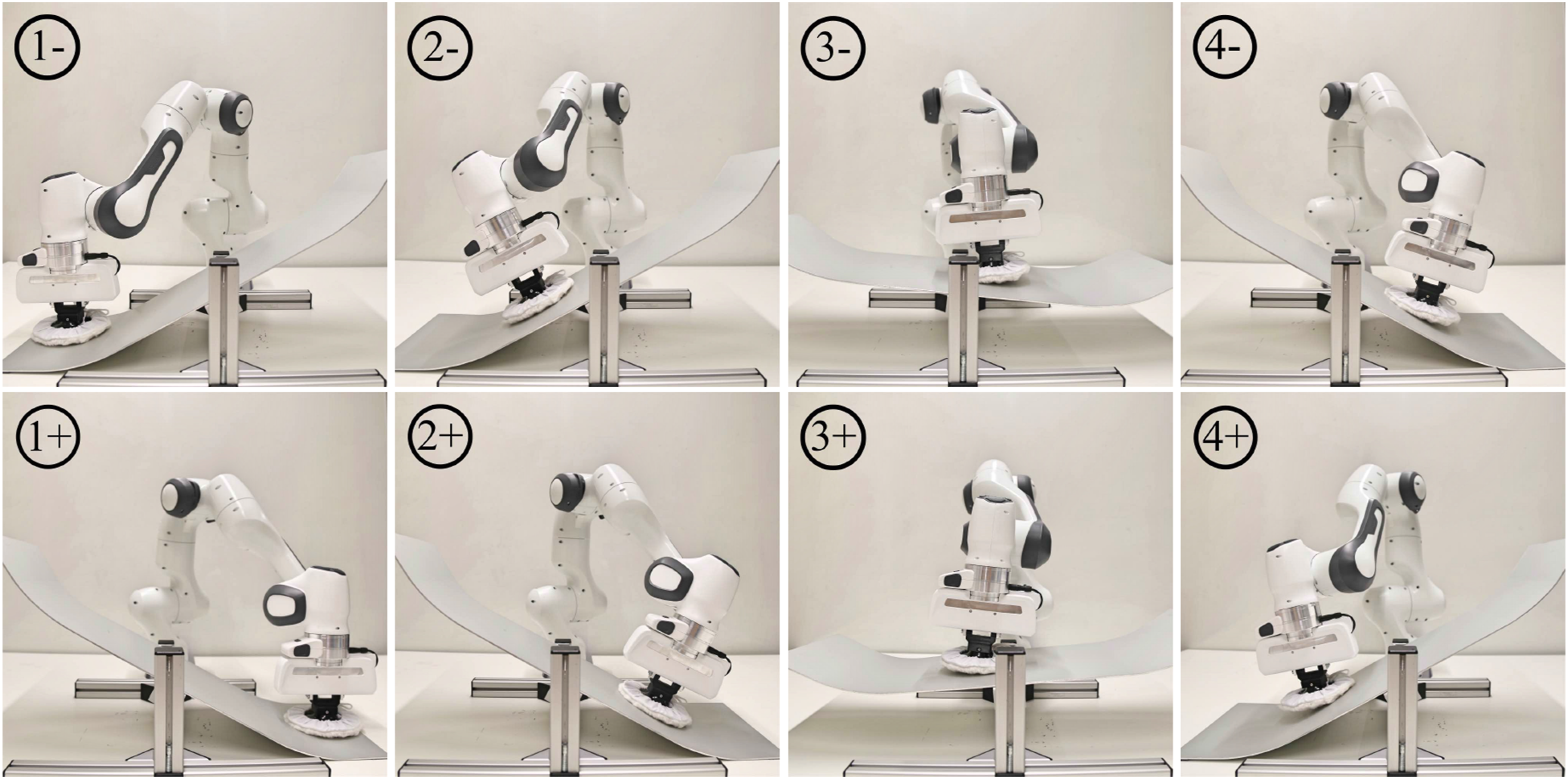
The experiment proceeds as follows, see Figure 10. The robot starts from an initial position ① and initiates sinusoidal polishing in x-direction and linear motion in y-direction. The desired setpoint depth is initiated slightly below the table surface. During the motion process ②, the end-effector pose adapts quickly to the inclination present in the geometry of the seesaw by regulating the desired moment to Experiment 4: Force error, impedance and force control tank energy, and end-effector position.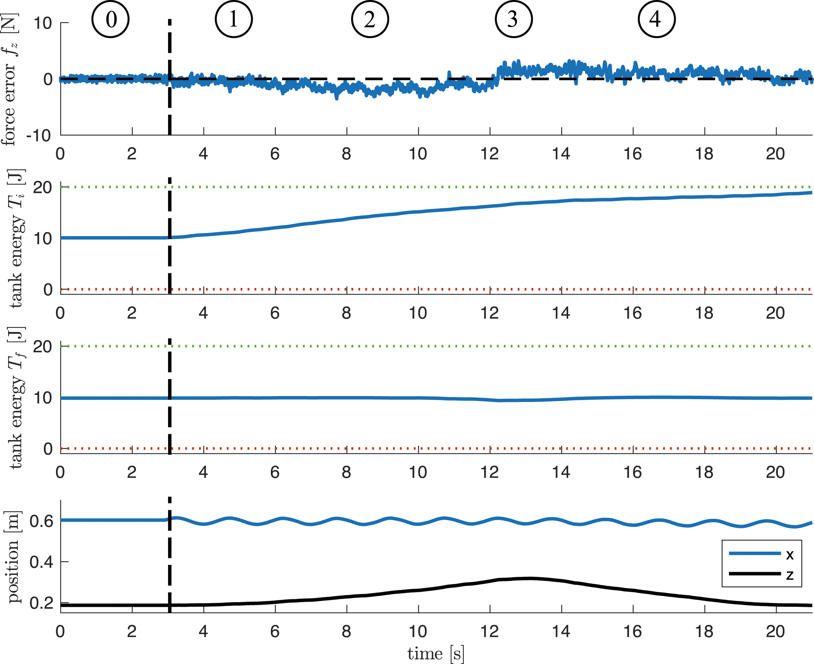
7.5. Experiment 5: The influence of energy tank limits
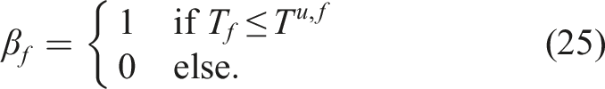
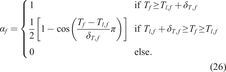
To show the effect of the tank with not enough energy, the previous experiment is performed multiple times in a row in a more dynamic setting. First, the lower tank limit is increased from 0 J to 5 J. Second, the desired velocity in y-direction is higher than before, and third, a higher force is commanded such that more energy is drained during the experiment. Looking at Figure 12 it can be seen that during the third iteration (i.e., ③) at t ≈ 23 s, the force controller tank energy is drained. This leads α
f
to switch from 1 to 0. As a result, the force controller is deactivated, and the force error reaches 25 N. In practice, when force control is applied without a solid contact, unintended robot motion in the direction of the desired wrench can occur. Through tank augmentation, we constrain the associated energy and thus this potentially hazardous motion. This is particularly crucial in scenarios involving contact loss, where failing to restrict the resulting robot’s acceleration could lead to an unsafe impact. The same rationale applies to the impedance control tank, as penetration of the desired trajectory into a contact may generate a significant interaction wrench, posing a potential hazard to both the robot and its environment. As demonstrated in this experiment, the tank effectively prevents such occurrences. Experiment 5: Force error, force controller tank energy, and lower limit key as well as end-effector position in z-direction.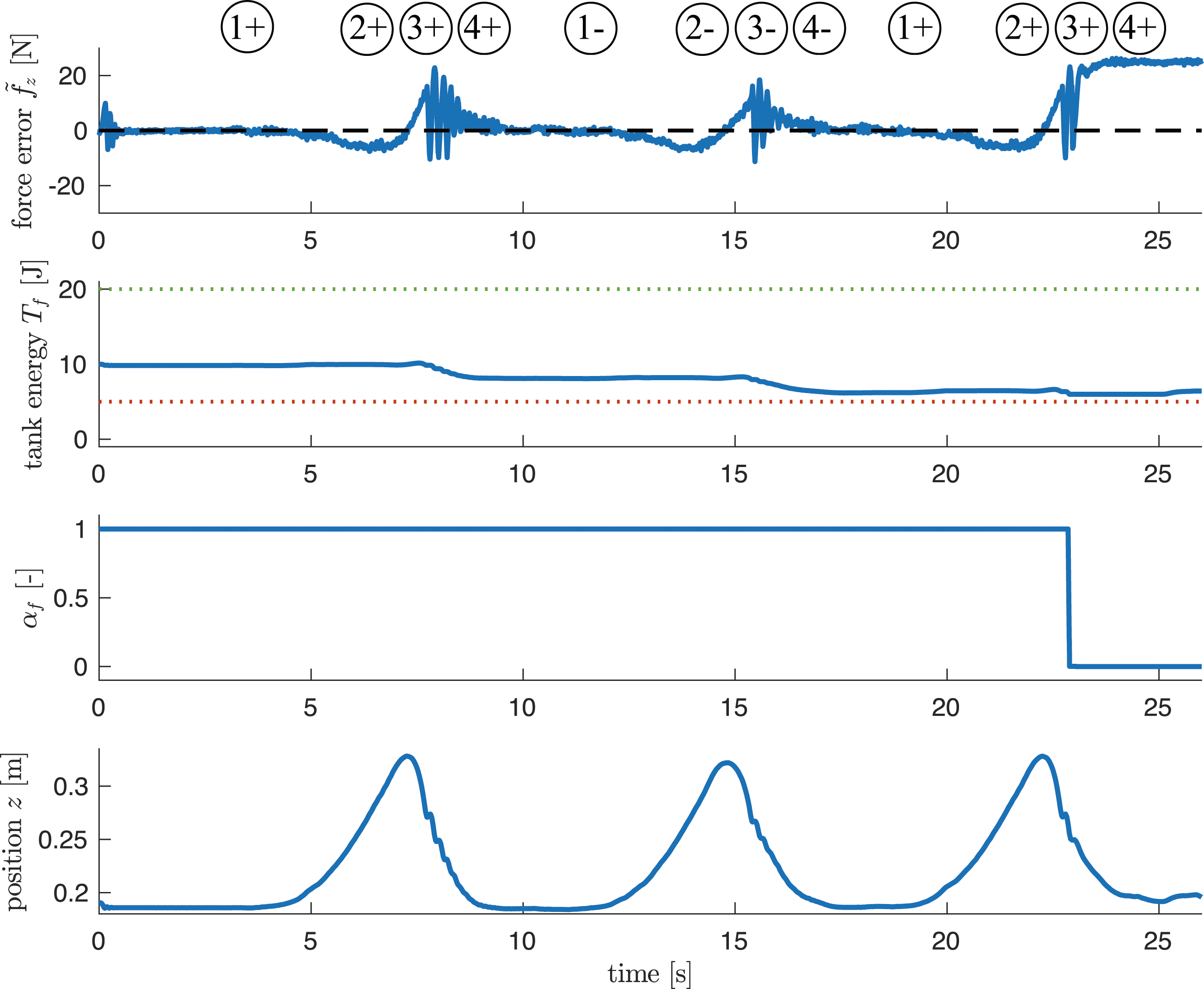
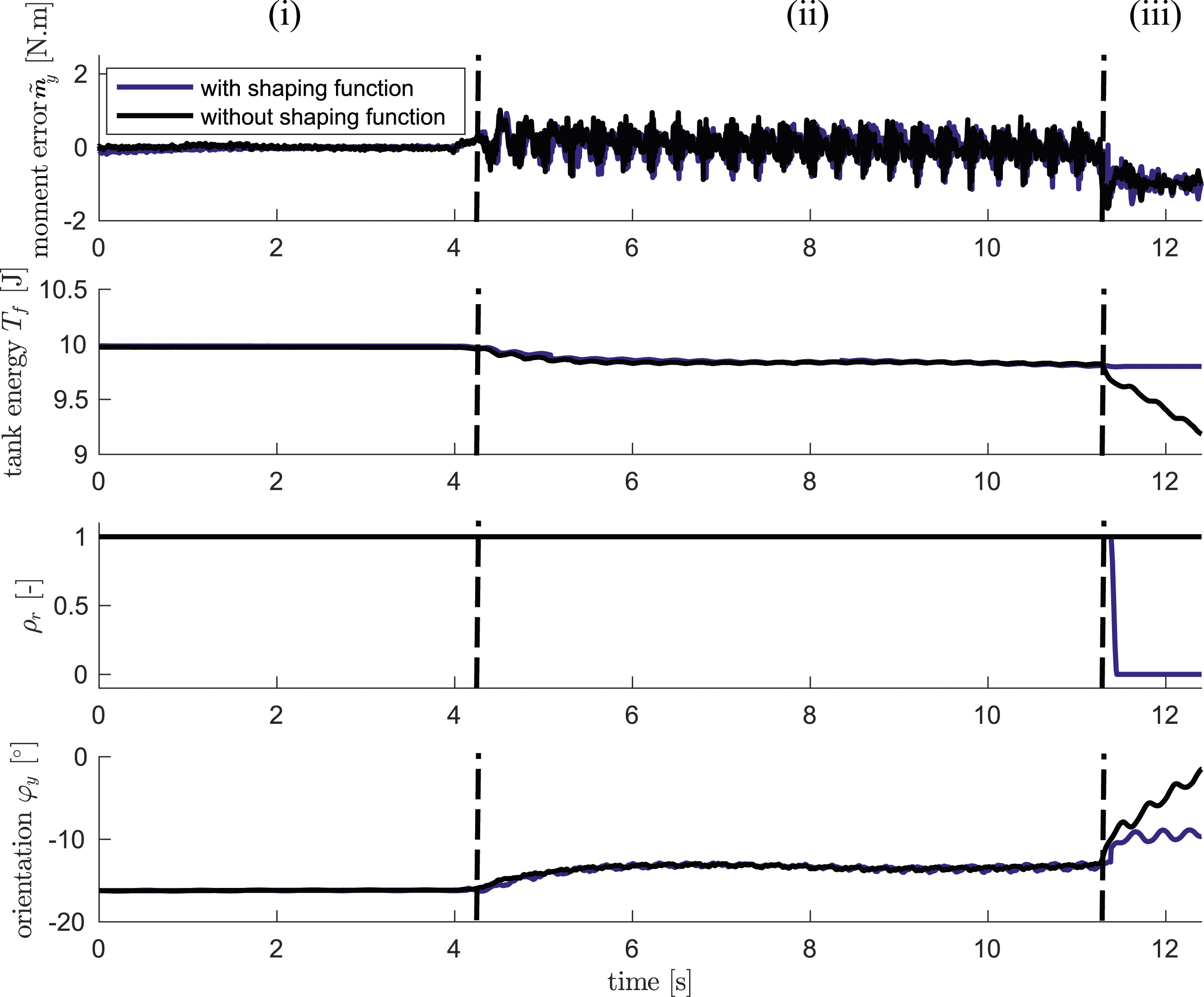
7.6. Experiment 6: Metal filing
The final experiment focuses on the regulation of rotational moments. For this, a metal filing application serves as a real-world evaluation task with the desired moment of Experiment 6: Phases of filing experiment. Experiment 6: Force error, force controller tank energy, shaping function, and end-effector orientation around y-direction.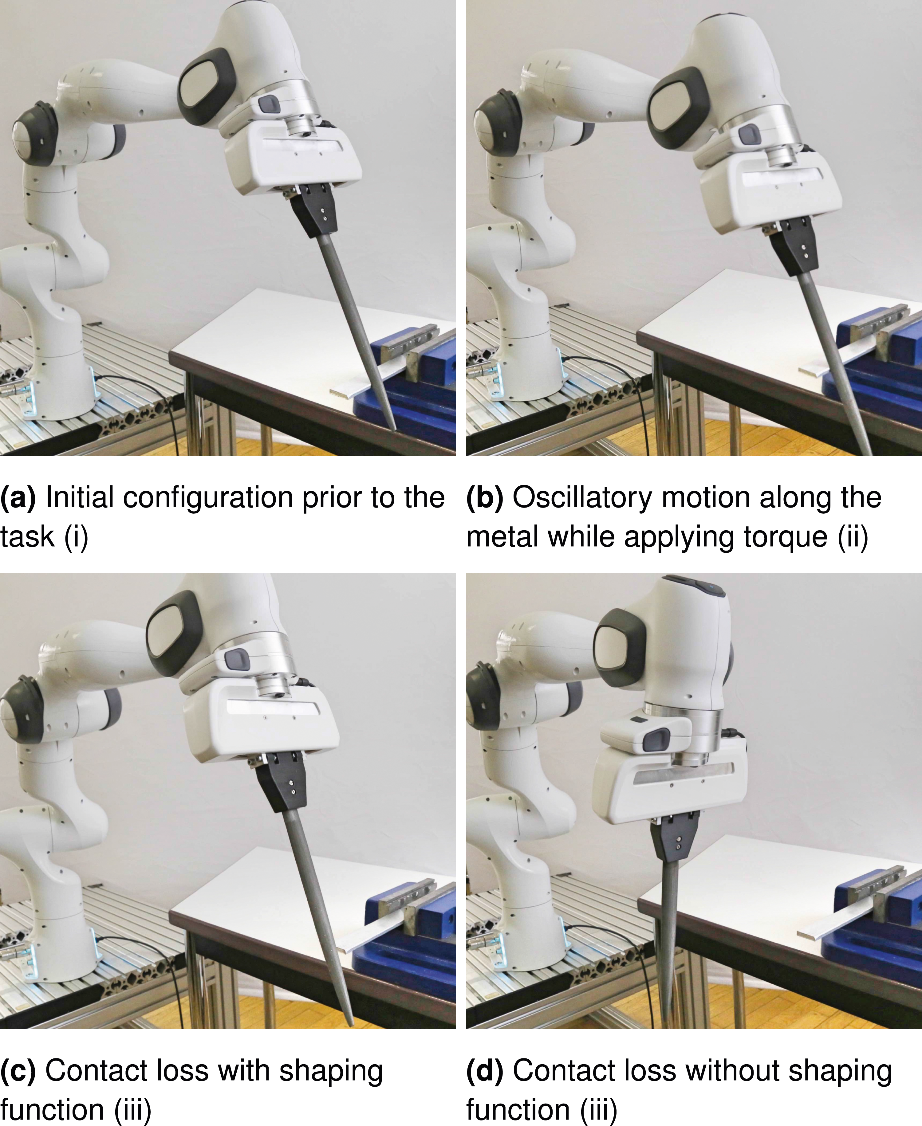
To sum up, the UFIC control framework allows for robust, safe, and accurate simultaneous control of forces, moments, and motion, allowing even extremely challenging contact manipulations such as filing or polishing under heavy process disturbances. Noticeably, the UFIC framework is fully integrated into the Franka Emika robots.
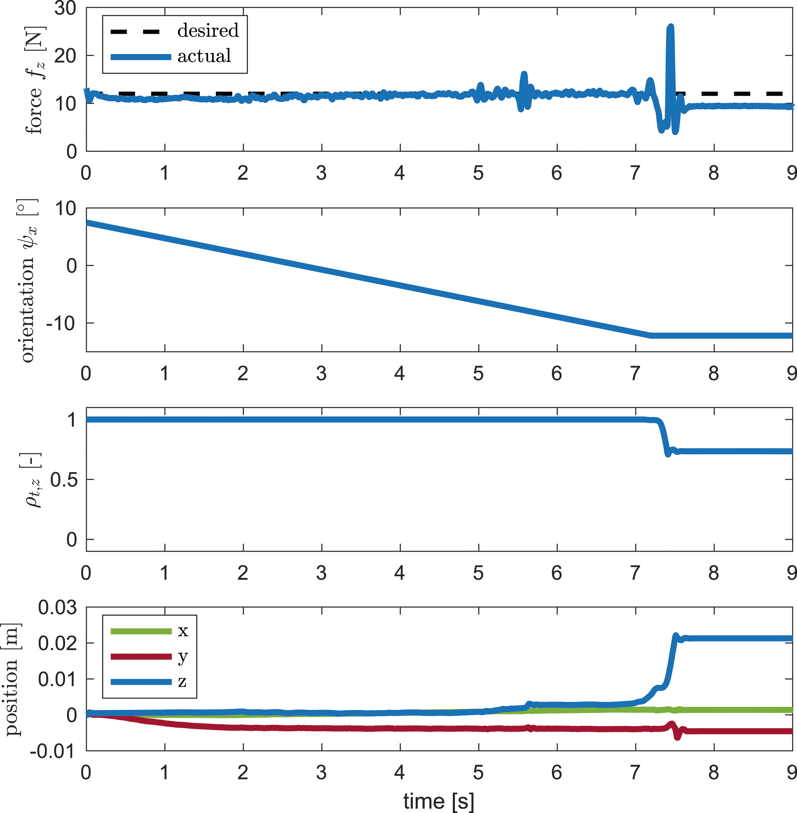
7.7. Experiment 7: Key insertion
In this experiment, the UFIC framework is utilized for a peg-in-hole task, specifically focusing on inserting a key into a keyhole (refer to Figure 15). The experimental setup begins with the robot positioned such that the key tip is in contact with the keyhole, yet the orientation of the end-effector remains heavily misaligned (Figure 15(a)). Consequently, the desired motion is configured to maintain a stationary position while continuously adjusting its orientation (Figure 15(b)). To ascertain the appropriate orientation, the output of the shaping function is consistently monitored. When this output begins to decrease, indicating alignment, the setpoint orientation is fixed. Throughout the experiment, force control is activated with a target force of 12 N in the end-effector’s z-direction. The stiffness of the impedance control in this direction is set to 0 N/m. Upon achieving alignment of the end-effector orientation with the keyhole, the force control is engaged to guide the key into the hole (Figure 15(c)). Figure 16 illustrates the variations in each variable throughout the experiment. Note that this is just one of many solutions one could generate with UFIC. Other strategies could involve active force patterns or combinations of both, leading to poking type behaviors. Experiment 7: Desired orientation is continuously adjusted until the key successfully enters the keyhole. Experiment 7: Interaction force, end-effector orientation around x-direction, shaping function, and end-effector position.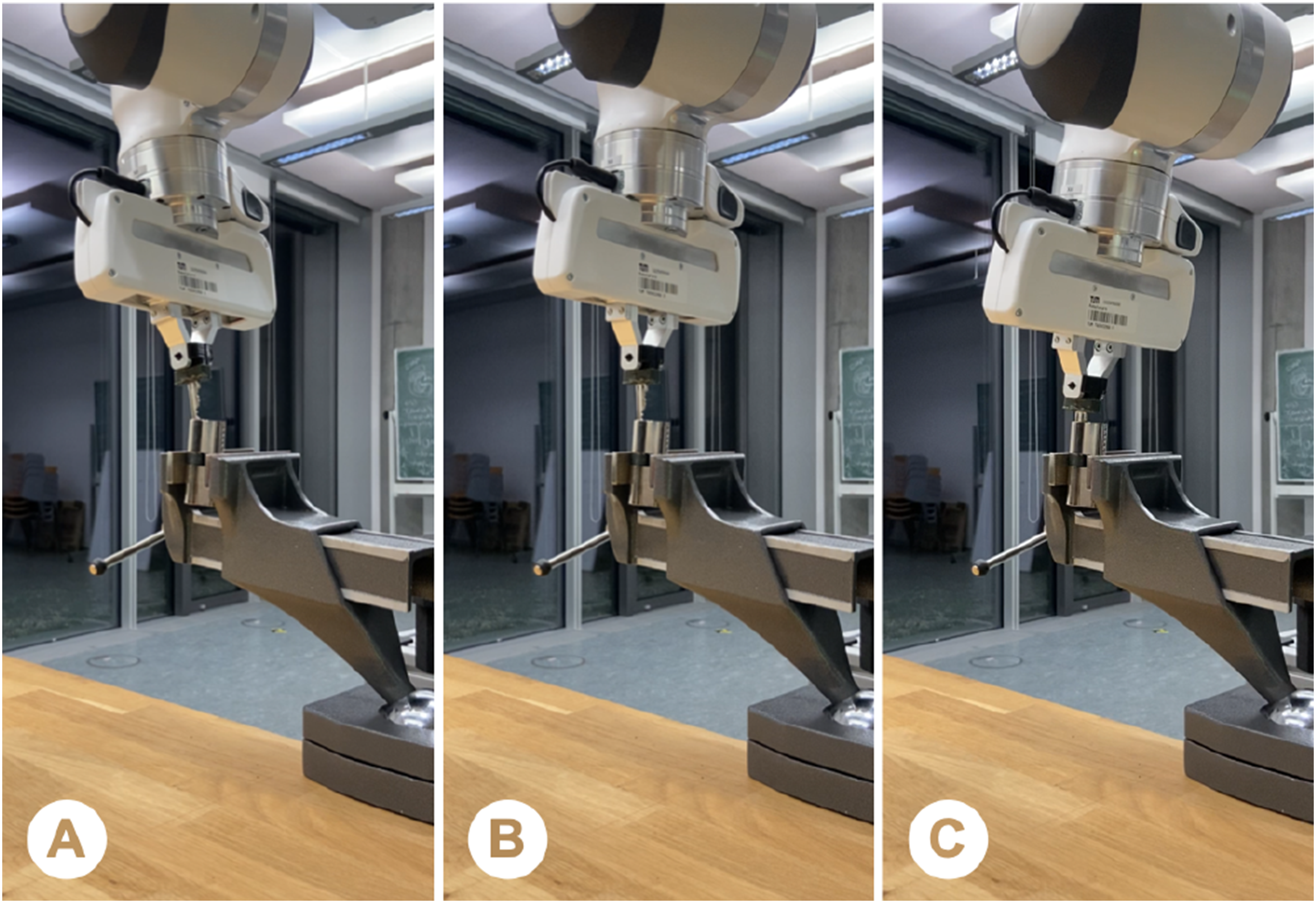
8. Conclusion
Due to limitations in performance, safety, and robustness, existing force control solutions still have not become a commodity control methodology in the real world. In this paper, we introduced a complete passivity-based framework for Cartesian force-impedance control with integrated contact-loss stabilization. To the best of the authors’ knowledge, this is the first industrially available framework under widespread use.
Specifically, we allow both rigid-body and flexible-joint robots to (i.) accurately and robustly regulate and track interaction forces, while (ii.) safely cope with unforeseen contact discontinuities.
The former is achieved by integrating enhanced force and impedance control algorithms with two distinct energy tanks. As the practical performance of the controller significantly depends on the specific energy level of the virtual tanks, energy initialization approaches for both tanks are introduced. These model-based approaches could be integrated with our previously proposed tank-based energy learning methods Shahriari et al. (2019) in order to address potential model inaccuracies. In our forthcoming work, we will concentrate on the practical implementation and evaluation of these aspects.
The latter ability is achieved by a position-based control shaping function that is parameterized with task-specific knowledge such as expected surface curvature or allowed tolerances. This way, no unwanted rapid motions due to contact loss may occur without deteriorating the control performance unnecessarily.
In summary, our solution is able to overcome many of the limitations and relevant problems that were still predominant in classical force and impedance control. For validation purposes, a series of specific experiments were carried out with a state-of-the-art joint torque-controlled tactile robot. Most importantly, even for time-varying and unforeseen environmental changes, our solution could achieve high levels of performance and robustness for complex force regulation and tracking problems under heavy disturbances. Noticeably, already numerous real-world industrial manufacturing and logistics cases were successfully solved with our framework. We also believe that space, health, and domestic applications will largely benefit from this work. An important step to be taken soon is the integration with suitable domain-driven (force-motion)-policy algorithms. This would ultimately bring tactile robotics and policy learning closer together, forming a powerful solution to learning and executing complex manipulation and interaction tasks. Extensions to the UFIC framework may also involve collaborative tasks, as demonstrated in our first works on multi-manual object lifting/carrying (Shahriari et al., 2022). Finally, note that the developed unification does not require a robot dynamics model. These are needed only for the impedance controller. As there exists a significant body of work on passivity-based impedance control, we refer the reader to the well-known works (Albu-Schäffer et al., 2007; Ott et al., 2008), emphasizing also the necessity of accurate dynamics models for high performance. In the UFIC framework, the unknown parts of the robot dynamics model may be assigned to a finite—yet undisclosed—amount of energy. Consequently, while such uncertainty definitely affects the achievable performance in an undesirable way, the overall system may still be proven to be passive, given the presented methodology.
Supplemental Material
Footnotes
Declaration of conflicting interests
The author(s) declared the following potential conflicts of interest with respect to the research, authorship, and/or publication of this article: Please note that S. Haddadin has a potential conflict of interest as a shareholder of Franka Emika GmbH.
Funding
The author(s) disclosed receipt of the following financial support for the research, authorship, and/or publication of this article: We greatly acknowledge the funding of this work provided by KBee AG and the Lighthouse Initiative Geriatronics, supported by StMWi Bayern (Project X, grant no. 5140951), as well as the Alfried Krupp von Bohlen und Halbach Foundation. Additionally, we express our gratitude for the funding received from the European Union’s Horizon 2020 research and innovation program, the ReconCycle project under grant no. 871352.
Supplemental Material
Supplemental material for this article is available online.
Notes
Appendix
Appendix: UFIC for flexible-joint robots
In this appendix, the UFIC framework is extended to the flexible-joint tracking case, which would allow for application to intrinsically elastic systems with constant joint impedance. Analog to the rigid case, the proposed system is passive by augmenting the same virtual energy tanks designed in the previous sections.
References
Supplementary Material
Please find the following supplemental material available below.
For Open Access articles published under a Creative Commons License, all supplemental material carries the same license as the article it is associated with.
For non-Open Access articles published, all supplemental material carries a non-exclusive license, and permission requests for re-use of supplemental material or any part of supplemental material shall be sent directly to the copyright owner as specified in the copyright notice associated with the article.