
Abstract
This paper presents a unique outdoor aerial visual-inertial-LiDAR dataset captured using a multi-sensor payload to promote the global navigation satellite system (GNSS)-denied navigation research. The dataset features flight distances ranging from 300 m to 5 km, collected using a DJI-M600 hexacopter drone and the National Research Council (NRC) Bell412 Advanced Systems Research Aircraft (ASRA). The dataset consists of hardware-synchronized monocular images, inertial measurement unit (IMU) measurements, 3D light detection and ranging (LiDAR) point-clouds, and high-precision real-time kinematic (RTK)-GNSS based ground truth. Nine data sequences were collected as robot operating system (ROS) bags over 100 mins of outdoor environment footage ranging from urban areas, highways, airports, hillsides, prairies, and waterfronts. The dataset was collected to facilitate the development of visual-inertial-LiDAR odometry and mapping algorithms, visual-inertial navigation algorithms, object detection, segmentation, and landing zone detection algorithms based on real-world drone and full-scale helicopter data. All the data sequences contain raw sensor measurements, hardware timestamps, and spatio-temporally aligned ground truth. The intrinsic and extrinsic calibrations of the sensors are also provided, along with raw calibration datasets. A performance summary of state-of-the-art methods applied on the data sequences is also provided.
1. Introduction
Last-mile goods delivery using drones is expected to bring about disruptive changes in logistical operations in the near future (Chen et al., 2022; Boysen et al., 2020). Rapid technological advancements and new legislation frameworks pave the way for large-scale implementation of last-mile goods delivery (Miranda et al., 2022; Pei et al., 2022; Aurambout et al., 2019). Corporations such as Amazon, Google, and DHL (Perreault and Behdinan, 2021) are testing autonomous drone delivery methods as an efficient alternative to traditional delivery methods to cope with the growing demand. Along with drones, full-scale aircraft are being investigated due to their high payload-carrying capability, operational safety, and longer flight times (Cohen et al., 2021). Autonomous flight of such platforms requires mapping the surrounding environment, means to perform collision avoidance, and means to plan and execute normal and emergency landing procedures (Yang and Wei, 2021; Cohen et al., 2021).
Autonomous navigation and mapping applications typically use a combination of visual (cameras), inertial measurement units (IMUs), light detection and ranging (LiDAR) sensors, radio detection and ranging (Radar), and global navigation satellite system (GNSS) receivers in their navigation pipeline. This sensor combination is prevalent in autonomous driving architectures (Zhang and Singh, 2014; Jiao et al., 2022; Ding et al., 2020), where the control system requires both the surrounding map and the current pose relative to the surroundings to plan its maneuvers safely. Multi-sensor fusion algorithms that are popular in this domain include visual-inertial odometry (VIO) (Qin et al., 2019; Gomaa et al., 2020; Thalagala et al., 2021), visual-inertial simultaneous localization and mapping (VI-SLAM) (Song et al., 2022), visual-inertial-LiDAR (VIL) odometry and mapping (Shan et al., 2021, 2020; Nguyen et al., 2021), and radar aided multi-sensor fusion methods (Liang et al., 2020; Adolfsson et al., 2022).
The development of these algorithms requires detailed testing and benchmark performance comparison. Publicly available datasets with ground truth are often utilized for this purpose. Several public datasets are available for autonomous driving algorithm development, such as KITTI (Geiger et al., 2013), NCLT (Carlevaris-Bianco et al., 2015), and 4Seasons (Wenzel et al., 2020). These datasets have a complete set of sensor data required to implement VI-SLAM or VIL architectures with critical metadata such as time synchronization between sensors and ground-truth data for benchmark performance. Additionally, these datasets were captured using vehicles in realistic driving scenarios, having long path lengths, varied lighting characteristics, and changing environmental conditions.
Compared to autonomous driving datasets, only a few are available for aerial multi-sensor fusion algorithm development. EuRoC (Burri et al., 2016) and Zurich-Urban (Majdik et al., 2017) are aerial datasets collected on experimental platforms focused on VI-SLAM developments with only camera, IMU, and ground-truth data; they excluded LiDAR sensor data. In EuRoC the data collection was carried out in indoor environments. NTU-VIRAL (Nguyen et al., 2021) dataset contains outdoor dataset with a VIL-capable sensing suite. The dataset trajectories include areas of open space, a parking lot, and an indoor environment comprising trajectory lengths of 100 − 500m. NTU-VIRAL dataset serves as a state-of-the-art benchmark for drone VIL navigation algorithm development for comparable short trajectories and scenery. However, when considering last-mile goods delivery applications, the expected trajectories will be much longer with added sensor degradation sources such as platform vibrations, higher altitudes, and changing sensor availability, particularly in the case of full-scale helicopters.
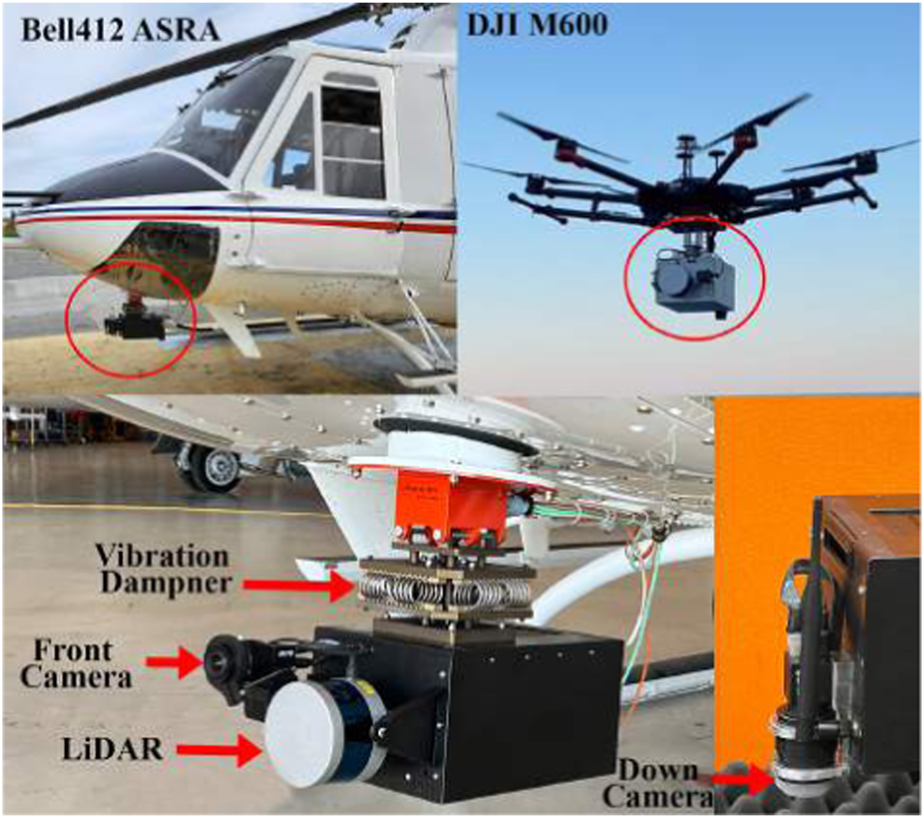
This paper presents a multi-sensor VIL aerial dataset captured on both a small-scale drone and a full-scale aircraft. The recorded data is intended to support the development of sensor fusion algorithms for last-mile goods delivery applications. Two batches of data were collected using a payload unit attached to a DJI-M600 hexacopter drone and an NRC Bell412 ASRA helicopter as shown in Figure 1. The payload unit consists of monocular cameras, an IMU, a 3D LiDAR scanner, a real-time kinematic (RTK) enabled GNSS receiver, and a Jetson AGX Xavier graphics processing unit (GPU) as the processing unit. The dataset has real flight platform sensor degradation characteristics like vibrations, operational flight altitudes and speeds, covering areas of urban towns, airports, highways, and prairies. The dataset contains time-synchronized post-processed ground truth to support benchmark performance comparison. To the best of the authors’ knowledge, this work presents the first publicly available full-scale vertical takeoff and landing (VTOL) vehicle visual-inertial-LiDAR aerial dataset with ground truth, suitable for VIL algorithm development. The contributions of this paper can be summarized as follows. • A novel publicly available visual-inertial-LiDAR dataset that includes full-scale aerial platform data with ground truth for VIL navigation algorithm development. • The dataset incorporates flight trajectories up to 5 km in outdoor environments to suit navigation algorithm development for last-mile goods delivery applications. • Evaluation results of state-of-the-art VIL navigation algorithms applied on the dataset to validate the suitability of the dataset to serve as a VIL navigation system design benchmark. MUN Sensor Payload Flight Test Configurations: NRC Bell 412 ASRA Nose Mount (Top/Bottom Left); MUN DJI-M600 air-frame mount top right.
The MUN-FRL dataset, which includes the flight sequences, post-processed RTK-GNSS ground truth, synchronization information, calibration parameters, and raw calibration sequences, are made available in the public repository: https://mun-frl-vil-dataset.readthedocs.io/en/latest/.
2. Related work
Publicly Available Dataset for Multi-Sensor Navigation Algorithm Development.
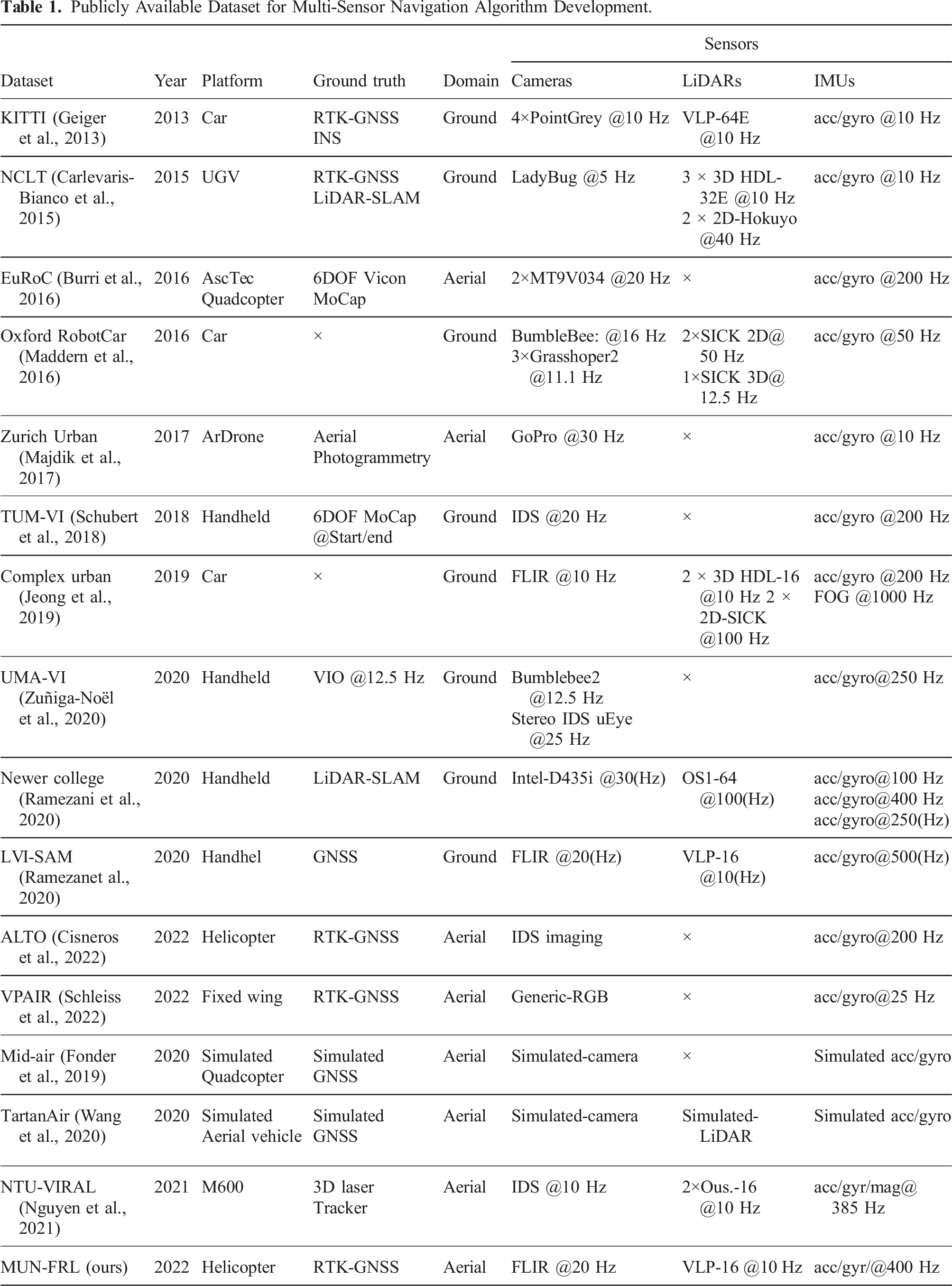
Ground platform datasets KITTI (Geiger et al., 2013), NCLT (Carlevaris-Bianco et al., 2015), Oxford RobotCar (Maddern et al., 2016), Complex Urban (Jeong et al., 2019), Newer College (Ramezani et al., 2020), and LVI-SAM (Shan et al., 2021) are heavily cited for visual-inertial-LiDAR navigation algorithm development. All these datasets contain at least one LiDAR scanner, monocular or stereo camera, IMU, and GNSS receiver. It is important to note that TUM-VI (Schubert et al., 2018), UMA-VI (Zuñiga-Noël et al., 2020), Newer College, and LVI-SAM datasets mentioned in Table 1 were collected using handheld sensor rigs while other ground platform datasets in Table 1 were collected with sensor suite mounted on a vehicle allowing to capture actual driving conditions, driving speeds, and sensor degradation sources such as platform vibrations.
The benchmark datasets available for VIL algorithm development generally include additional supporting information such as time synchronization between sensors, sensor calibration parameters, and ground truth. Time synchronization between multiple sensors reduces the estimation drift caused by the timing inconsistencies of individual sensor clocks (Faizullin et al., 2022). The datasets NCLT, Oxford RobotCar, and Complex Urban provide timestamps that can be used to synchronize sensing data using received time stamps. However, due to inherent clock drift, the sensors are not guaranteed to capture data synchronously with each other. Additionally, the received time stamps include message transfer delays when recording data. Datasets such as KITTI, Newer College, and LVI-SAM report hardware time synchronization between the clocks of each sensor, which accurately synchronizes sensor data with time stamps references to a common clock, for example, GNSS clock.
Accurate calibration of intrinsic and extrinsic parameters reduces estimation drift in multi-sensor fusion algorithms (Schubert et al., 2018). This may include parameters related to camera intrinsic calibration, camera-IMU extrinsic calibration, camera-LiDAR extrinsic calibration, and GNSS-IMU extrinsic calibration. These critical parameters are provided in datasets such as KITTI, NCLT, Oxford RobotCar, Complex Urban, Newer College, and LVI-SAM.
Ground-truth data is essential for the performance evaluation of multi-sensor fusion algorithms. Ground platform datasets typically provide ground-truth data as GNSS positions. Coarse meter-level GNSS ground-truth data was provided in Oxford RobotCar and NCLT datasets. The datasets such as Complex Urban, KITTI, Newer College, and 4Seasons (Wenzel et al., 2020) provided centimeter-level RTK-GNSS platform positioning information.
When considering aerial platforms, visual-inertial datasets are more prevalent, with most aerial datasets considering a minimum payload sensing suite, that is, stereo or monocular camera and IMU. The EuRoC dataset contains hardware time-synchronized stereo camera and IMU data captured in indoor environments with changing trajectory speeds and lighting conditions. The dataset provides post-processed ground truth with a sub-centimeter level accuracy using a motion capture system, calibration information, and raw calibration data. The intended application of EuRoC dataset is GNSS-denied indoor navigation. Zurich Urban captured a single 2 km long outdoor dataset using a tethered micro aerial vehicle (MAV) in an urban environment. The Zurich Urban dataset contains software time-synchronized data with meter-level GNSS position ground truth. The Mid-air dataset (Fonder et al., 2019) provides a visual-inertial dataset using an Unreal engine-based simulator, resulting in photo-realistic synthesized data to support navigation algorithm development. The ALTO dataset (Cisneros et al., 2022) and VPAIR dataset (Schleiss et al., 2022) were collected using a helicopter and a light aircraft, respectively, reaching altitudes up to 300 m. These datasets are intended for visual place recognition and localization tasks, providing GNSS-inertial navigation system (INS) ground truth location data, IMU data, laser altimeter measurements, and RGB images captured from a downward-facing camera. The trajectories covered in these datasets span ranges of up to 100 km.
Compared to ground platform datasets, there is a significant shortage of aerial platform datasets available for VIL algorithm development. Payload weight limitations have mainly restricted the use of LiDAR scanners on MAV platforms. The TartanAir dataset generates a synthetic aerial VIL dataset using an Unreal engine-based simulator to support SLAM applications. The dataset includes stereo RGB images, depth images, segmentation data, optical flow information, camera poses, and LiDAR point clouds. Recently published NTU-VIRAL dataset utilized a moderately heavy payload
3. Sensor setup
We have developed a platform-agnostic multi-sensor payload unit, enabling us to capture datasets with similar sensors on different platforms. This design allows for testing and evaluation using a drone, which benefits from fewer regulations and test flight preparations than full-scale aircraft. The sensors necessary for VIL navigation algorithm implementation are already available in small form factors, enabling them to be used in interchangeable operations.
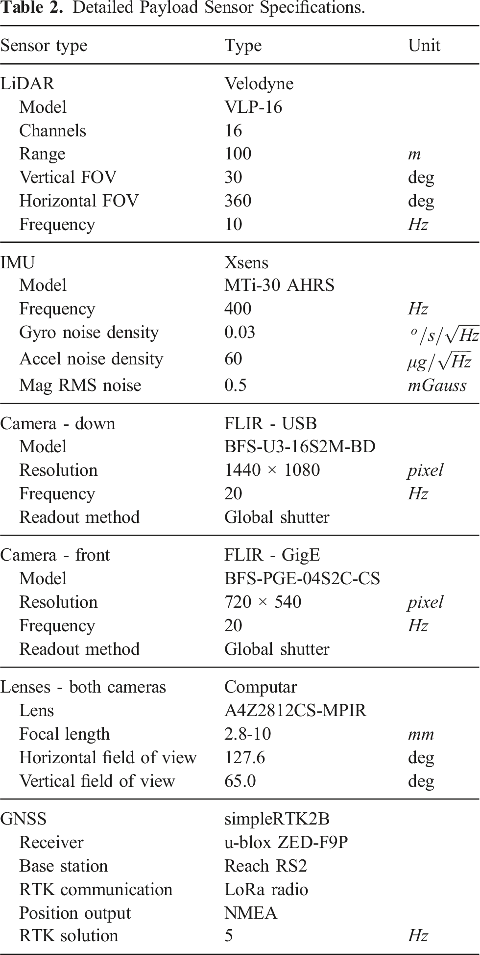
Detailed Payload Sensor Specifications.
The LiDAR of the payload is rigidly attached, facing downwards. The two cameras are rigidly mounted with one front-facing and the other downward-facing, as shown in Figure 2. In the MUN-FRL dataset and its evaluations, we have limited the data feed to the downward-looking camera as it provided the most information for navigation algorithms and stable estimation throughout the flight trajectories. Sensor payload, key coordinate frames, and dimensions.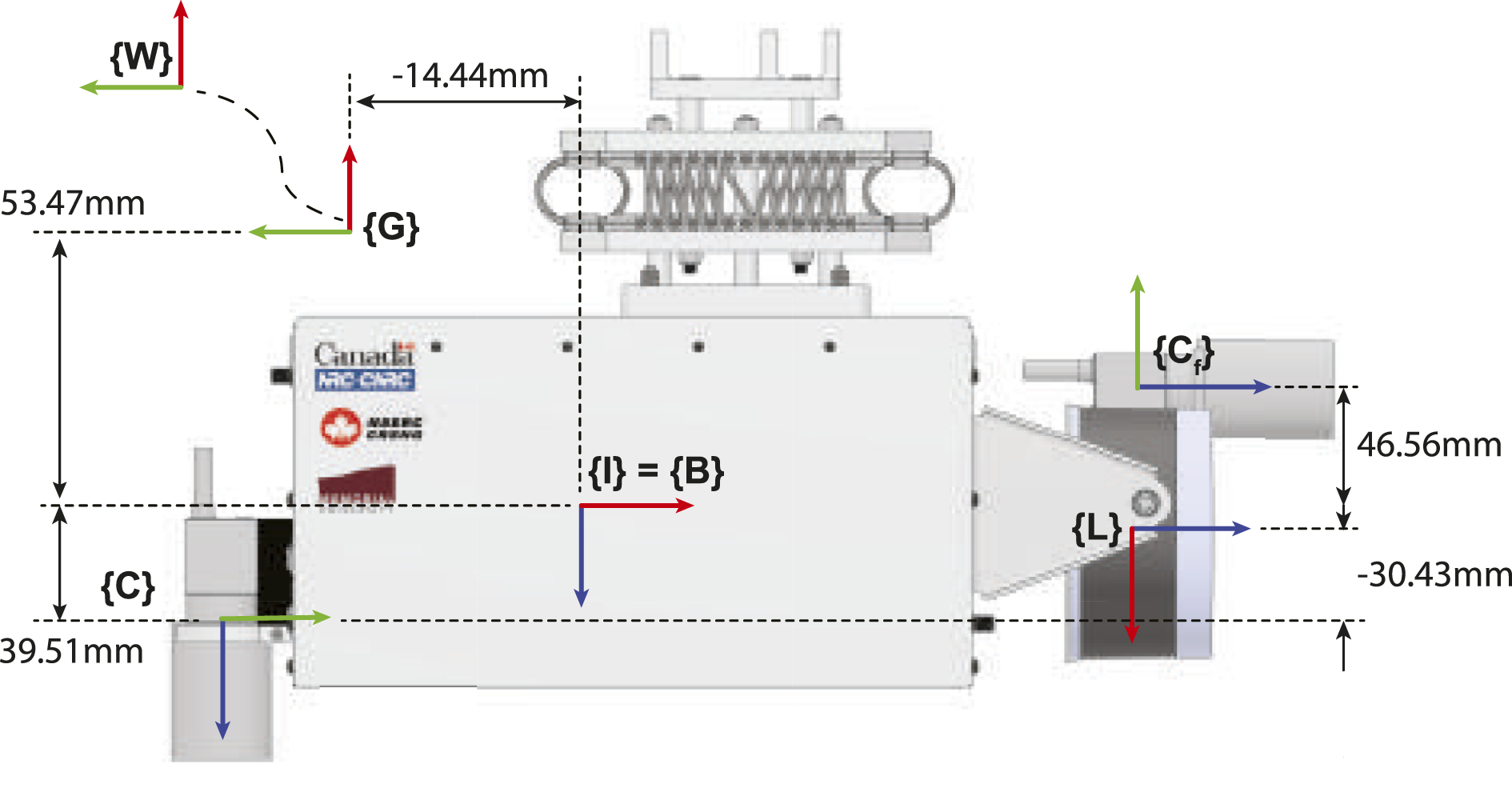
Figure 2 illustrates the coordinate frames associated with the sensors. The X, Y, and Z axis are represented by red, green, and blue, respectively, and defined as follows: the IMU frame, denoted as {I}, is equivalent to the body frame {B}, the front camera frame is denoted as {C
f
}, the down camera frame is denoted as {C}, the LiDAR frame is denoted as {L}, the GNSS receiver antenna frame is denoted as {G}, and the East-North-Up (ENU) frame of reference is denoted as {W}. Figure 3 shows the sensor frames rigidly connected with the IMU coordinate system {B}. The dotted line represents the changing relative pose Schematic view of sensor coordinate frames (red) and corresponding transformations (black).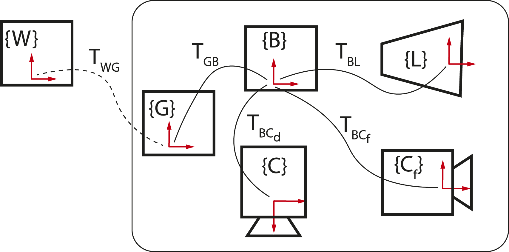
The convention used to describe the spatial transformations of the sensors is as follows. A transformation matrix
4. Sensor calibration
This section presents the calibration methods used to determine intrinsic and extrinsic parameters for each sensor of the payload unit. Calibration was performed in four main steps: camera intrinsic, IMU intrinsic, camera-IMU extrinsic, and camera-LiDAR extrinsic calibration. The resulting calibration parameters were stored in a “calibration.yaml” file for each batch of data captured on the Bell412 and DJI-M600 platforms.
4.1. Camera intrinsic calibration
The intrinsic parameters of the cameras include the camera projection matrix and the lens distortion model parameters. These were found using the camera calibration tool provided in the VINS-Fusion package (Qin et al., 2019) following the instructions mentioned therein. These camera calibration parameters are included in the “calibration.yaml” file.
4.2. IMU intrinsic calibration
IMU measurements are commonly assumed to be corrupted by white noise with standard deviation σ n and a random walk noise with standard deviation σ w . The Xsens MTi-30 data sheet provides nominal values for these parameters, requiring refinement for accurate probabilistic modeling of IMU measurements. Therefore, a separate calibration has been carried out using the method described in Schubert et al. (2018). The refined parameters are included in the “calibration.yaml” file.
4.3. Camera-IMU calibration
The spatial transformation between camera and IMU, and time-offset (t
d
) between camera and IMU measurements were found using the open source Kalibr package Furgale et al. (2013). Spatial transformation matrix
4.4. Camera-LiDAR calibration
The spatial transformation between the camera and LiDAR ( Camera-LiDAR calibration methodology (Left: Initial calibration using Matlab toolbox, Right: Fine-tuning the calibration using dataset images.).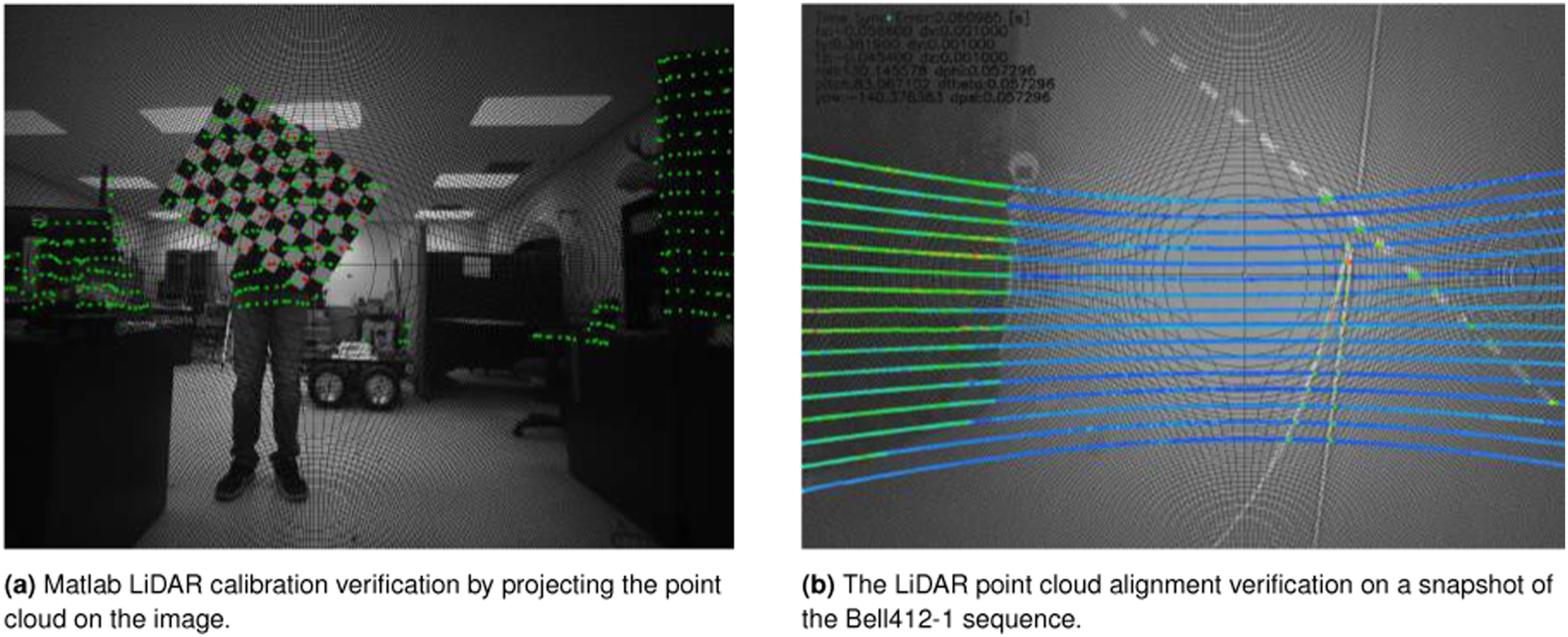
4.5. IMU-GNSS calibration
IMU-GNSS extrinsic calibration, that is,
5. MUN-FRL dataset
5.1. Dataset description
The dataset includes two batches of data sequences collected by interchanging the multi-sensor payload unit between a DJI-M600 drone and the NRC Bell412 ASRA helicopter. Inside the payload unit, all the sensors were connected to a Jetson AGX Xavier GPU running ROS. The sensors were publishing data as ROS messages and then recorded as a single ROS bag file. The ROS bags were saved using an internal solid-state drive (SSD) connected to the Jetson AGX Xavier.
5.2. Sequence description
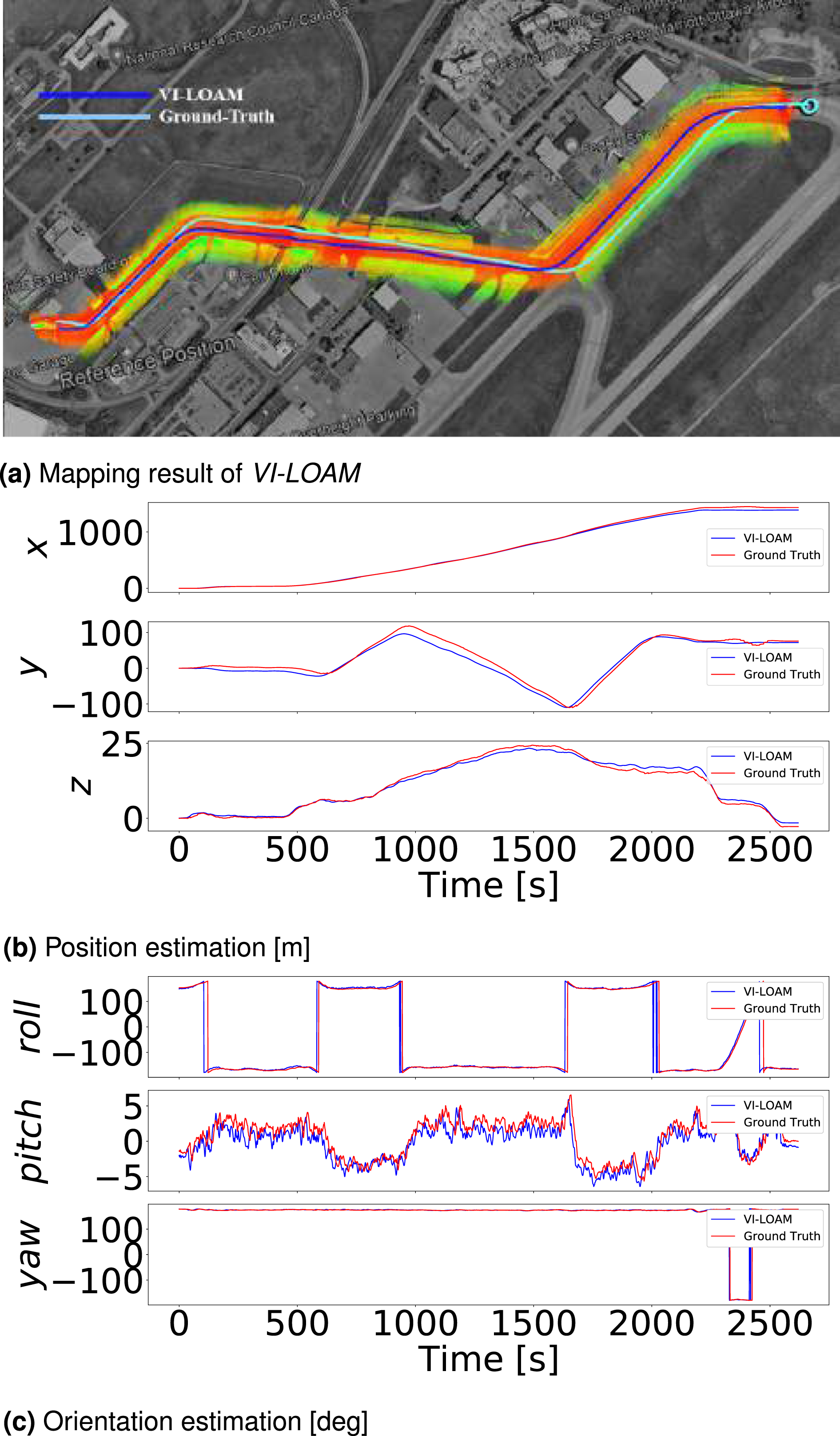
The data sequences in this study attempt to mimic last-mile goods delivery missions by starting at one point and ending at another with lengths of up to 5 km. Some sequences include partially overlapping trajectories and multiple loops. For example, Figures 5 and 6 display the two trajectories of Bell412 sequences. VI-LOAM results on the Bell412-6. Useful LiDAR points are only available at the beginning and at the end of the dataset. VI-LOAM results on the Bell412-1 dataset. The terrain is predominantly flat since this is a low altitude flight over the main taxiway from the hanger.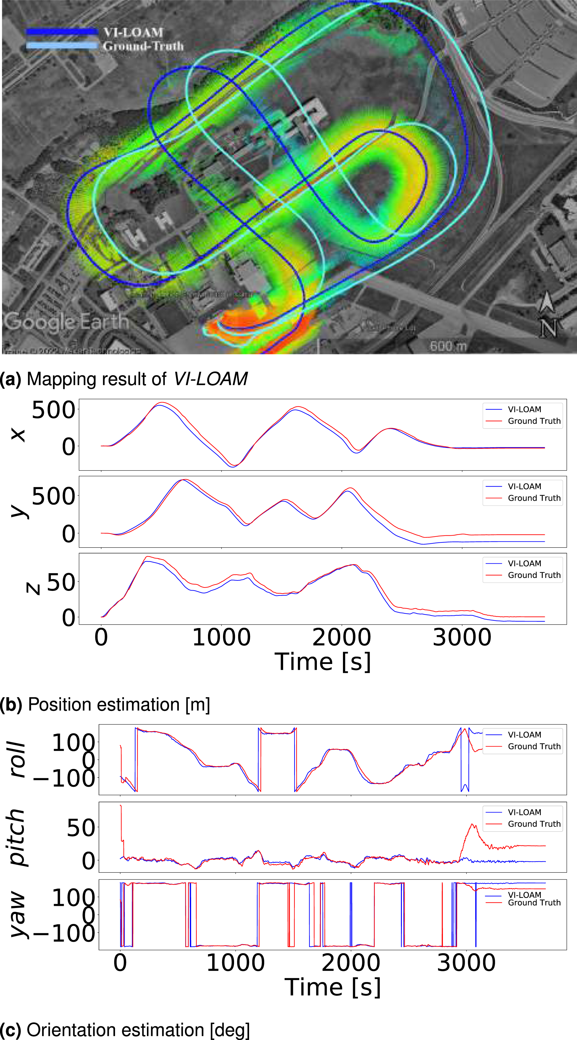
Dataset Organization and Sequence Descriptions.
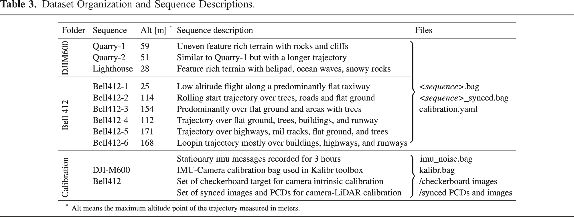
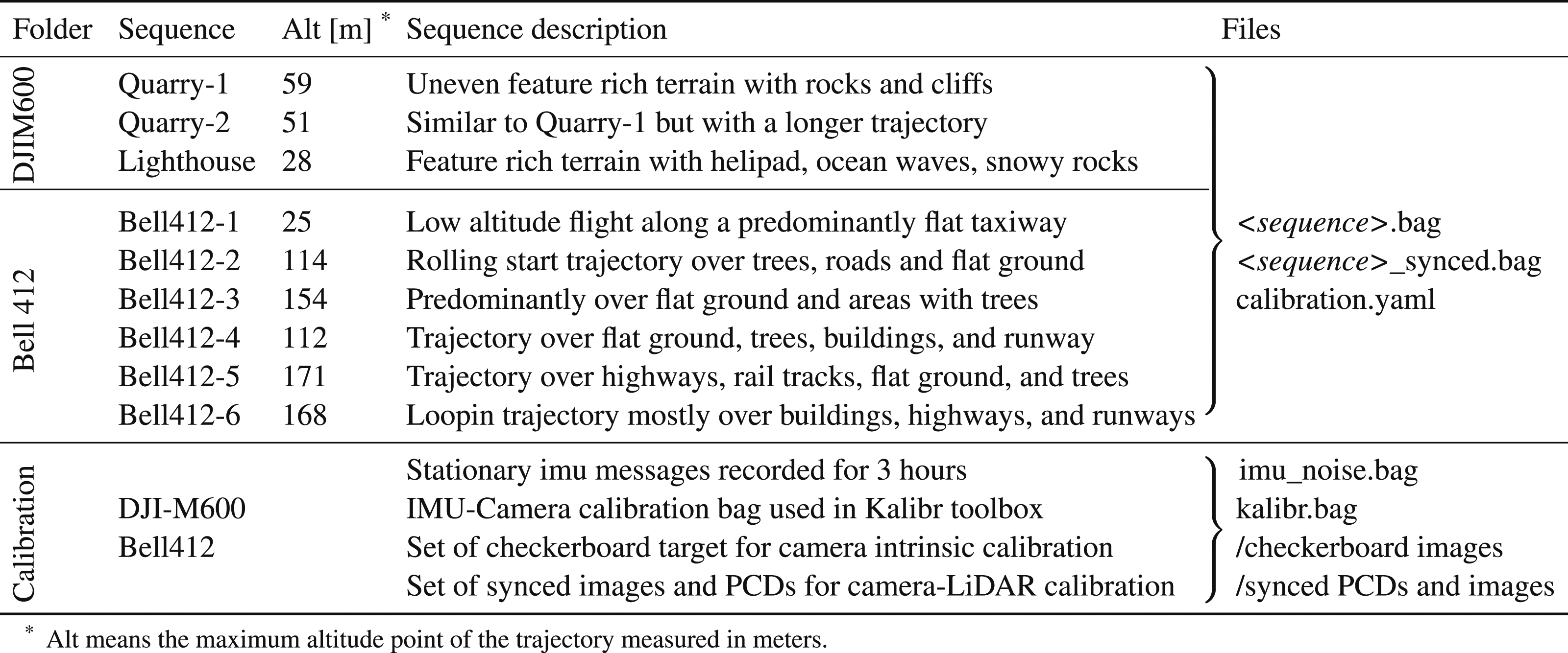
5.3. Data format
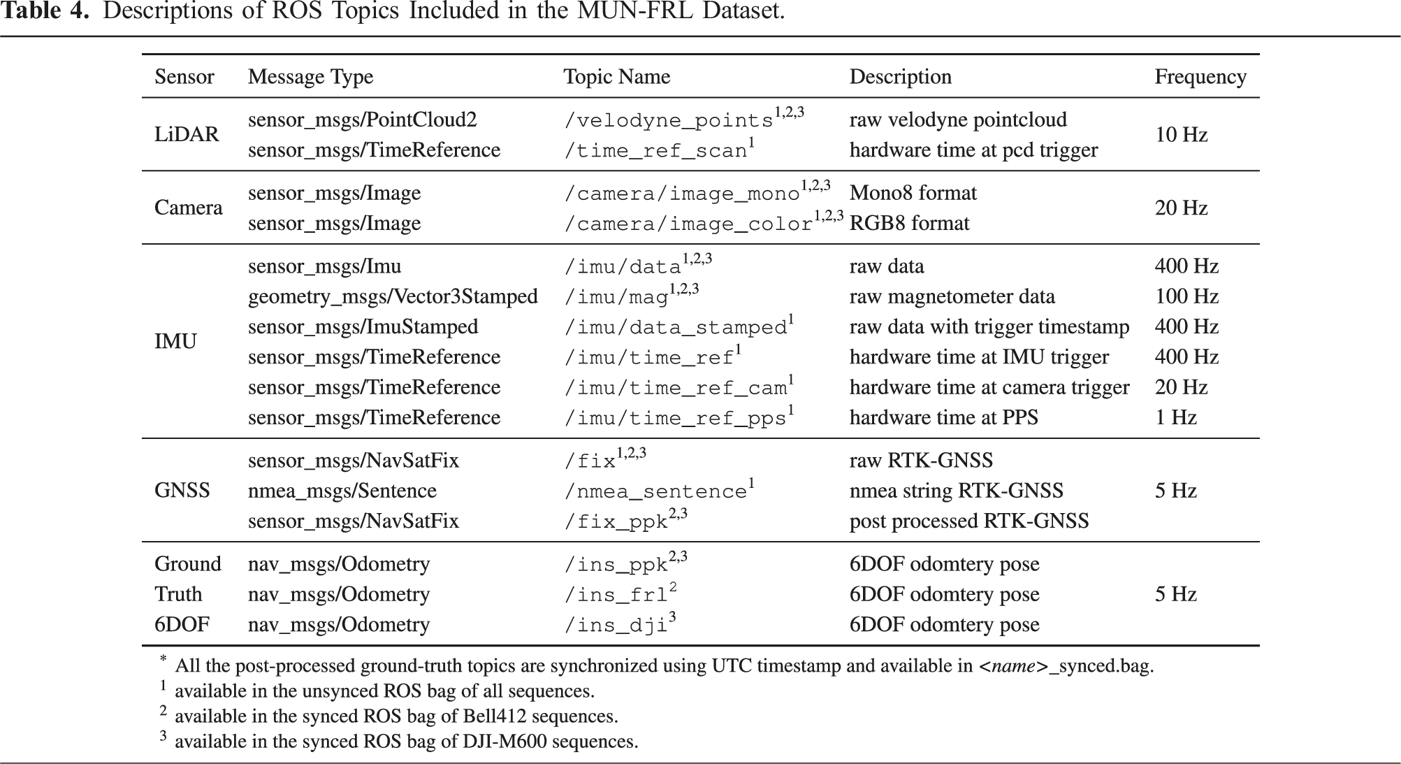
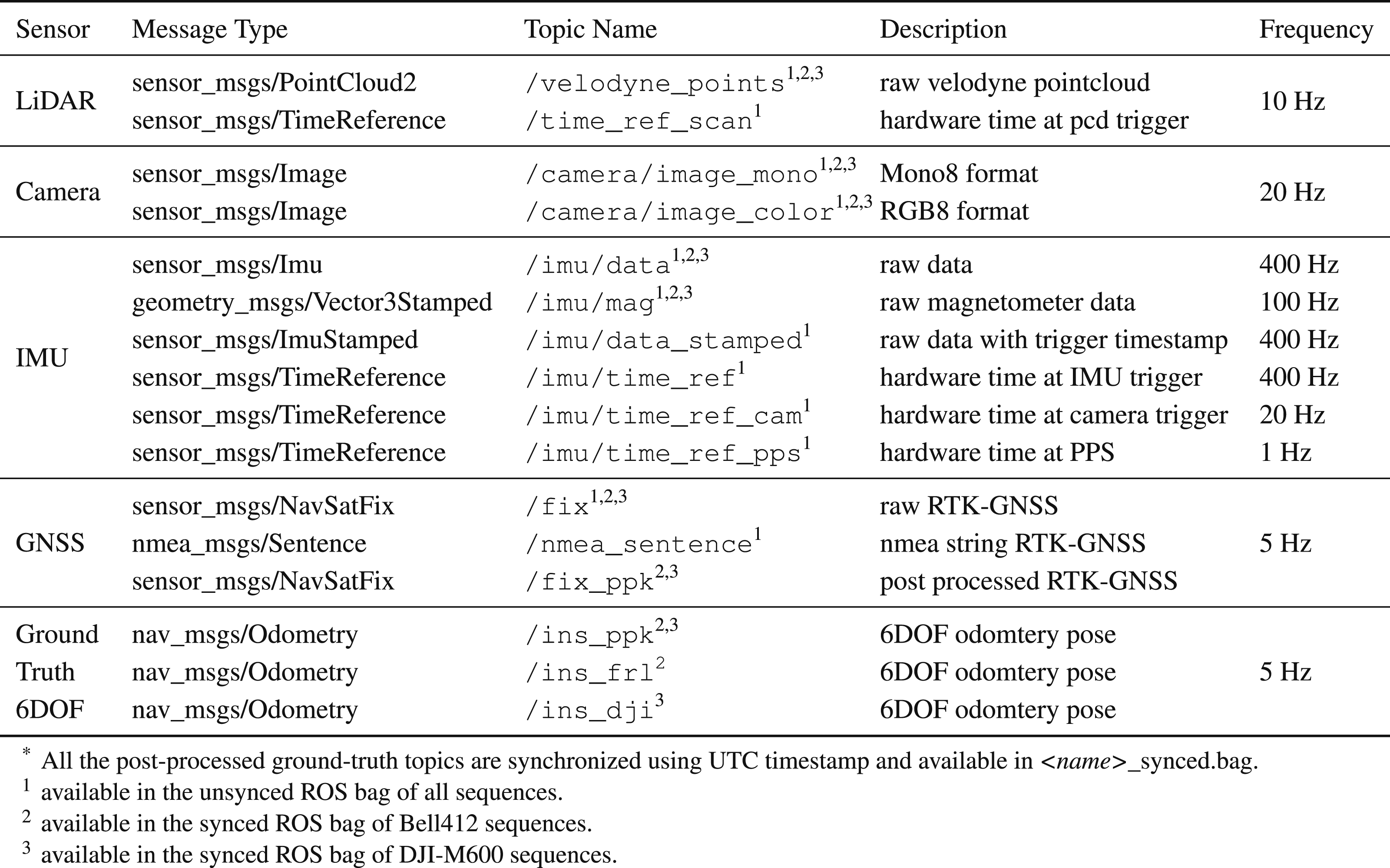
5.3.1. ROS bag files
Descriptions of ROS Topics Included in the MUN-FRL Dataset.
5.3.2. Calibration files
In the MUN-FRL dataset, the calibration parameters are different between DJI-M600 and Bell412 sequences. Therefore, for ease of use, we provide calibration parameters in a “calibration.yaml” file for each sequence of the dataset. The file includes the intrinsic parameters of the camera and IMU, and extrinsic parameters between camera-IMU, camera-LiDAR, and IMU-GNSS sensors. The transformation matrices are provided following the standard OpenCV matrix convention. Additionally, we provide calibration data sources that were used for IMU noise quantification, camera calibration, camera-IMU calibration, and camera-LiDAR calibration applicable for both the DJI-M600 sequences and the Bell412 sequences of the dataset.
5.4. Time synchronization scheme
The synchronization of sensors in the payload unit was achieved through hardware time synchronization using the pulse per second (PPS) signal from the GNSS receiver. The PPS signal is an absolute time reference from the GNSS satellite clock, which reduces the clock drift of the sensors. The PPS signal was fed into the synchronization management module (SMM), which generated a GPGGA NMEA (Faizullin et al., 2022) message for the LiDAR, allowing it to publish point-cloud messages with synchronized time stamps. The IMU also supplied the PPS signal to synchronize its clock, which then triggered the camera.
The IMU publishes a PPS time synchronization scheme.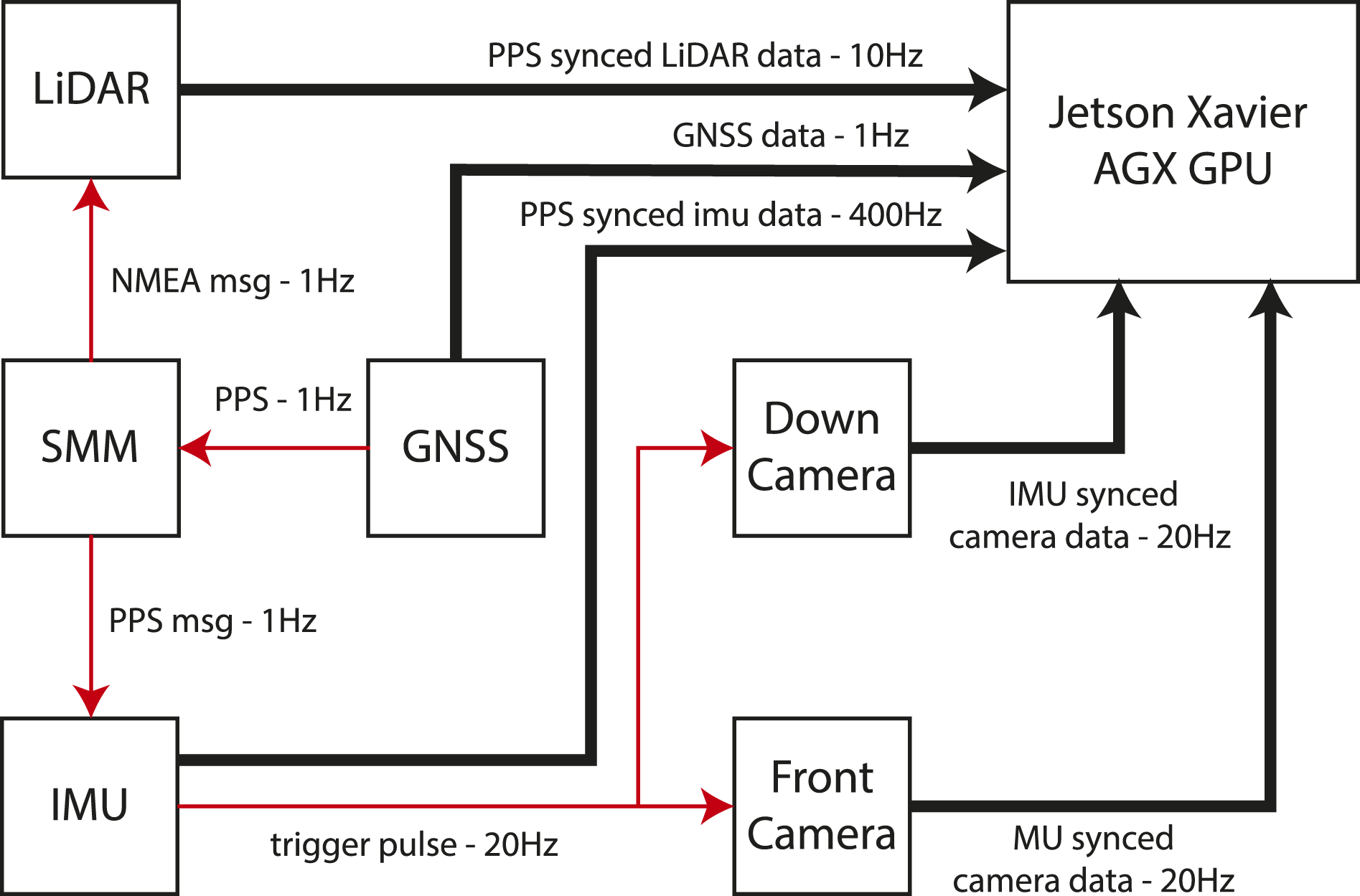
5.5. Ground-truth data
In order to facilitate VIL algorithm evaluation, we provide four types of GNSS-based ground-truth data for all our data sequences. First, we provide the
It is recommended to use
6. Dataset evaluation
To assess the dataset suitability as a benchmark for multi-sensor fusion algorithms, we evaluated its performance using state-of-the-art estimation algorithms, including a visual-inertial algorithm VINS-Fusion (Qin et al., 2019), a Lidar-only odometry algorithm A-LOAM (Cao and Cui, 2019), a LiDAR-inertial odometry algorithm FAST-LIO2 (Xu et al., 2022), and a visual-inertial and LiDAR combined algorithm VI-LOAM (Didula et al., 2022). VI-LOAM is a combination of VINS-Fusion and the LiDAR-only odometry algorithm A-LOAM to achieve a combined VIL solution. The results of our evaluation are presented in Table 6. Note that the VINS-fusion algorithm used here is capable of incorporating GNSS and loop closure constraints. However, these updates are disabled when calculating the solution in Table 6, that is, only the visual-inertial solution from the algorithm is shown. The ” × ” indicates the algorithm failed for the corresponding sequence.
6.1. Evaluation criteria
To evaluate the performance of multi-sensor fusion algorithms on our data sequences, we incorporated commonly used evaluation criteria (Schubert et al., 2018; Qin et al., 2019), which are presented below.
6.1.1. RMSE position [m]
The root mean squared error (RMSE)-position is computed by comparing the tracked positions 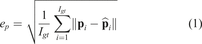
The total number of ground-truth data indices is denoted by I gt . To perform a length-normalized evaluation of the results, the RMSE drift [%] is calculated by dividing the RMSE position [m] by the length of the sequence.
6.1.2. RMSE angle [deg]
This metric measures the root mean squared difference between the ground-truth orientation 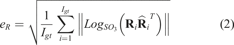
Ground-truth data indices are denoted by I gt while the RMSE angle [%] is calculated similarly to RMSE position [%].
In order to calculate the RMSE position and RMSE angle, the /ins_ppk topic of each sequence was used, that is, the VINS-Fusion solution of each sequence with PPK-GNSS factors enabled in the factor graph.
6.2. Results
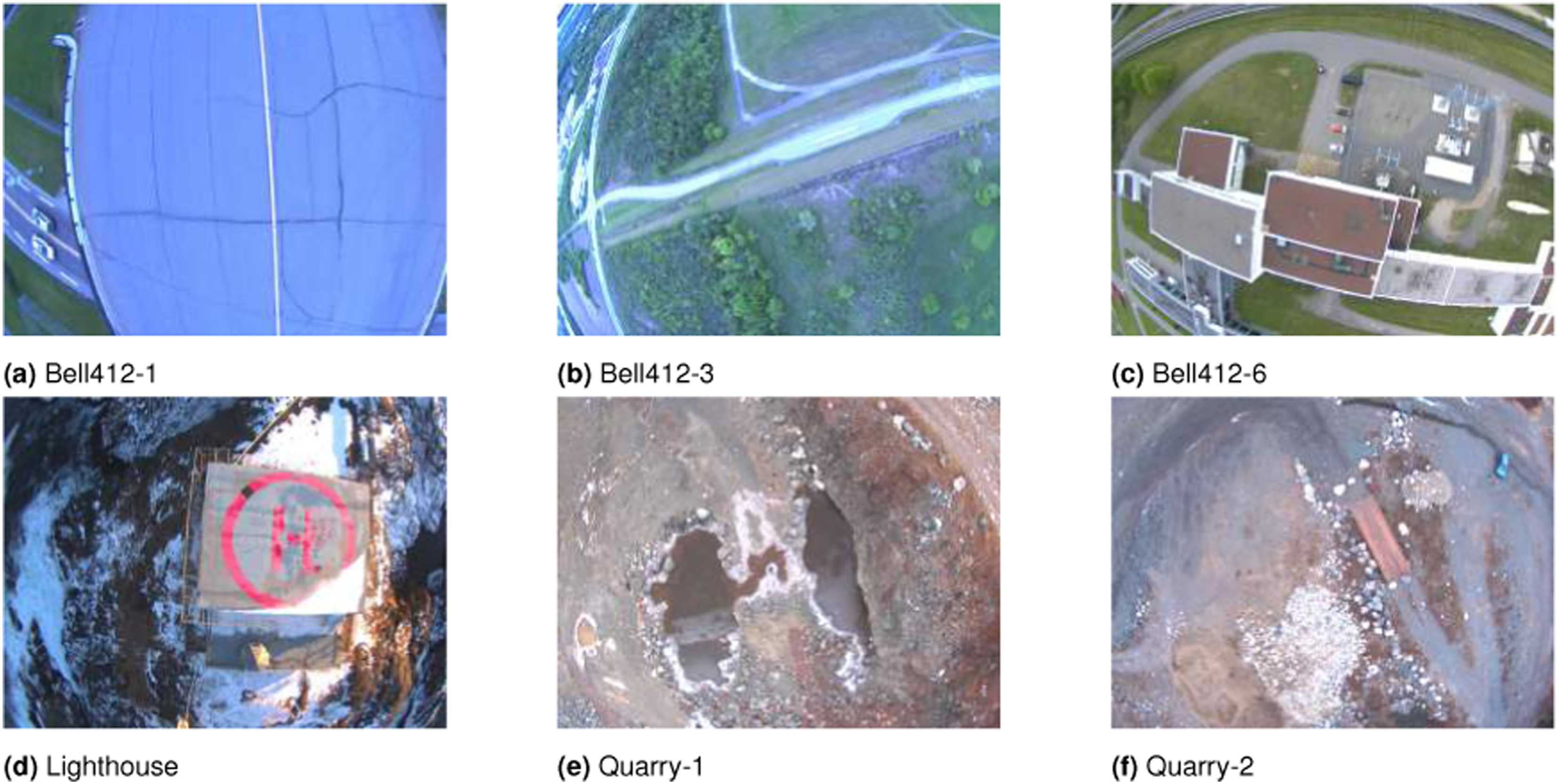
This section presents the evaluation results of the data sequences. Figure 8 indicates trajectories of Bell412 sequences and Figure 9 DJI-M600 sequences. Trajectory estimation results of Bell412 sequences: Bell412-[1 to 3] (Top Row), Bell412-[4 and 5] (Bottom Row). The red line shows the ground truth trajectory. The presented results are obtained with real-time time-synchronized data and calibrated sensors using the VI-LOAM. Trajectory estimation results of DJI-M600 sequences: Quarry-1, 2 and Lighthouse. The red line shows the ground truth trajectory. The presented results are obtained with real-time time-synchronized data and calibrated sensors using VI-LOAM. Sample snapshots of scenes captured in each dataset sequence.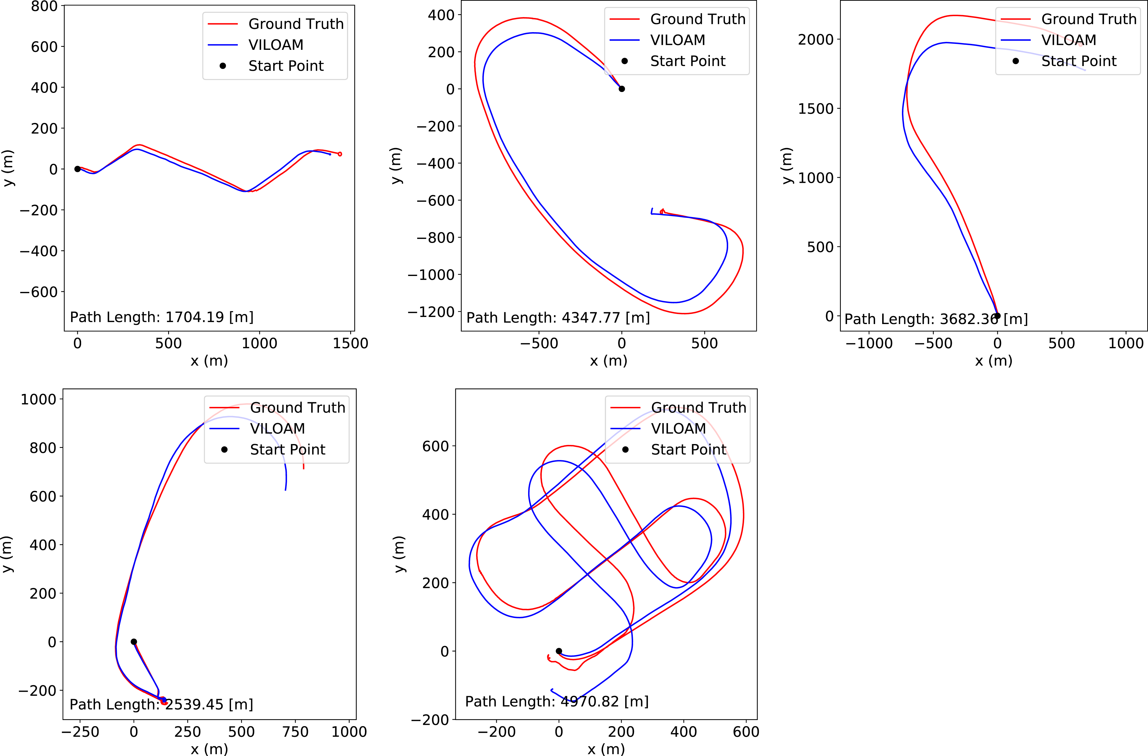

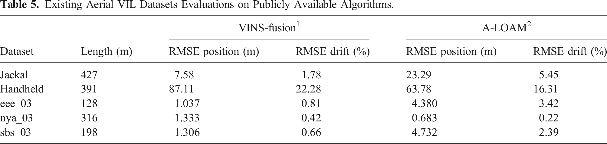
Existing Aerial VIL Datasets Evaluations on Publicly Available Algorithms.
State of the art Estimation Method Comparison for the Datasets.
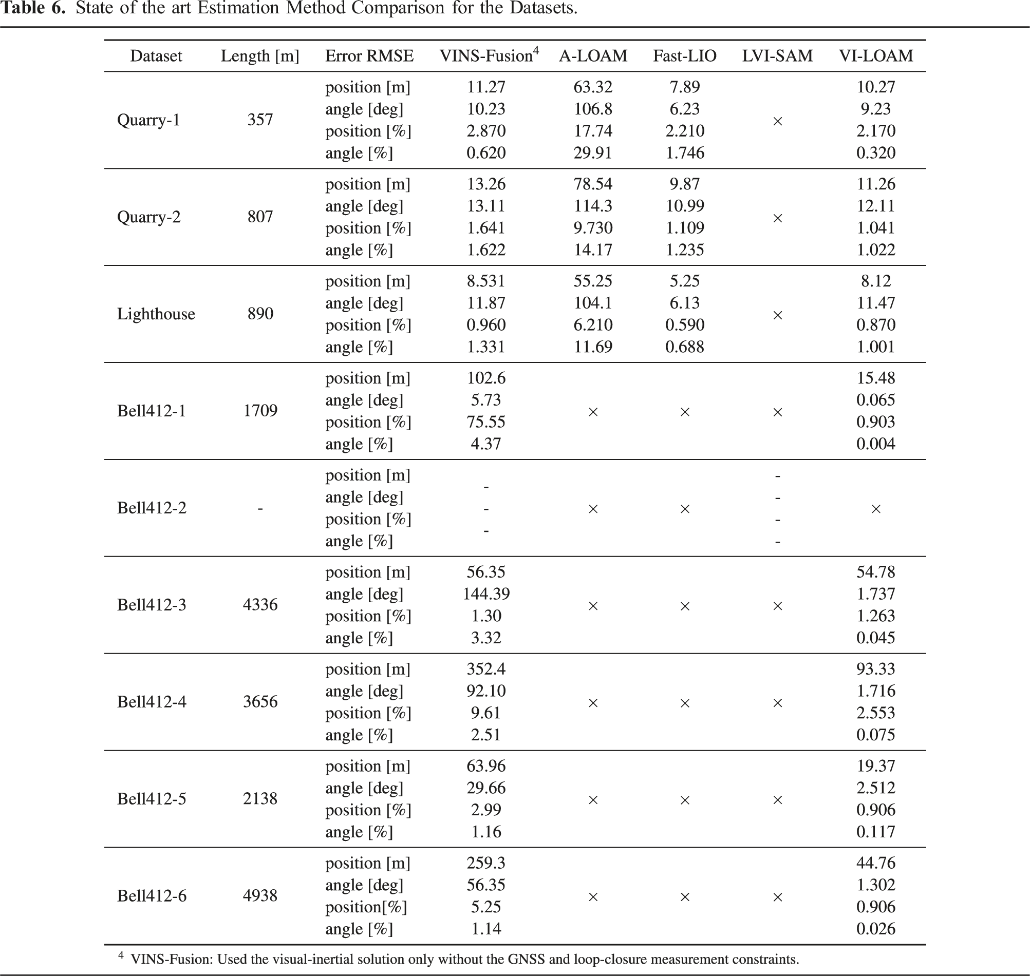
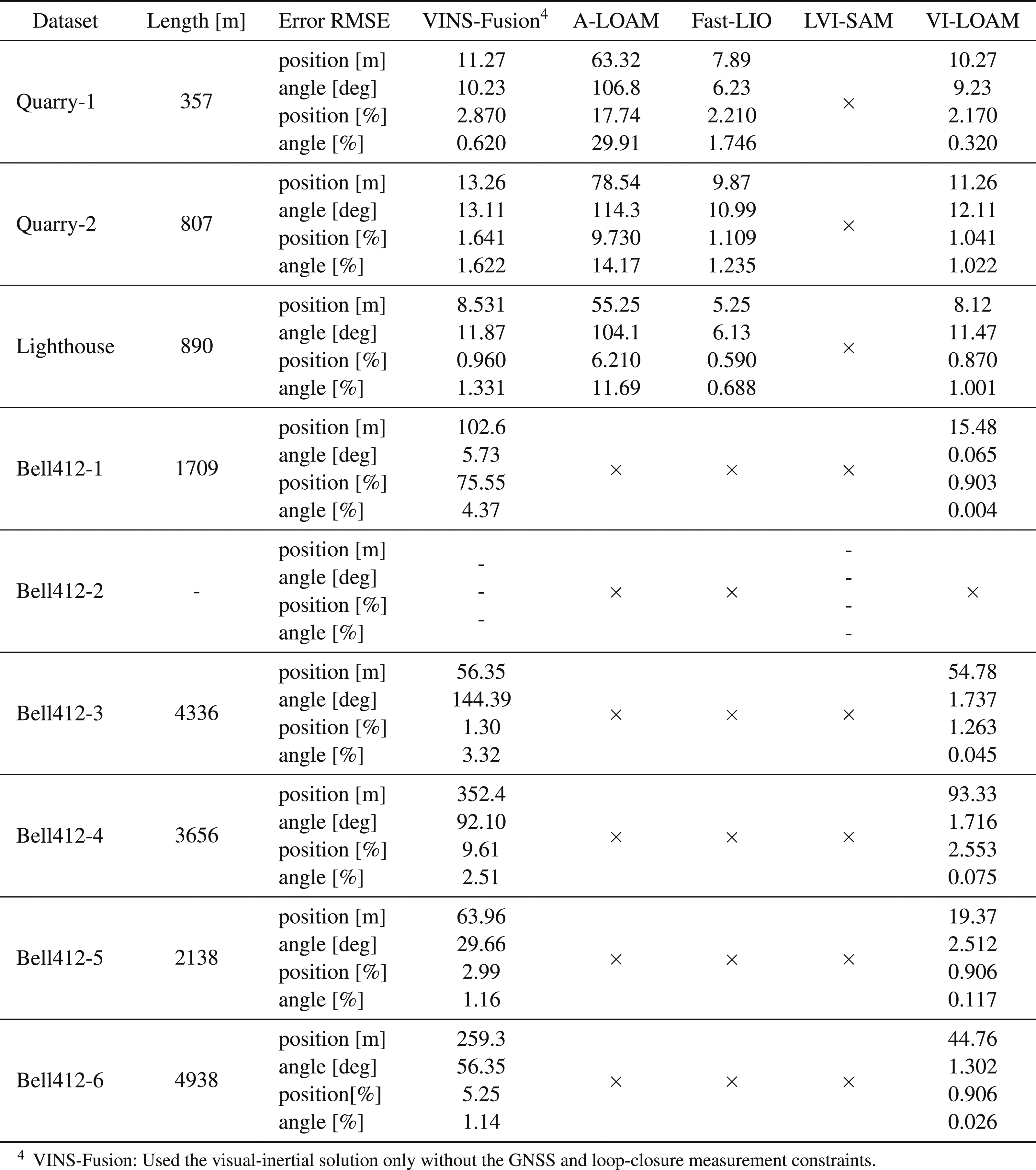
In our evaluation, the VINS-Fusion algorithm could estimate the trajectories for all the sequences until the end, except for Bell412-2. The rolling initialization of the Bell412-2 sequence caused the VINS-Fusion algorithm to fail since it is not designed to handle such scenarios. This sequence is publicly made available to test the rolling initialization capability of VIL algorithms.
The FAST-LIO2 algorithm estimated the trajectories for all DJI-M600 sequences, which had structured terrains and were flown at altitudes between 20m and 60m. However, FAST-LIO2 failed for all Bell412 sequences. In particular, Bell412-1 sequence had a low-altitude flight over a structure-less terrain, that is, an airport runway, which caused the algorithm to fail. The other Bell412 sequences were comprised of high-altitude (25m − 170m) flights, resulting in low LiDAR point registrations and a lack of features in the point-clouds in mid-flight, which also led to the failure of FAST-LIO2 algorithm.
The VI-LOAM combines the A-LOAM and VINS-Fusion algorithms to suit both structured and non-structured environments seen in the dataset. To validate its suitability for multi-sensor GNSS-denied navigation, the VI-LOAM algorithm was evaluated using our dataset. By incorporating visual, LiDAR, inertial, and compass information for state estimation, it successfully estimated the trajectories for all sequences from start to end. Example results are presented in Figures 5 and 6, showing trajectory and mapping results for the VI-LOAM algorithm applied to the Bell412-1 and Bell412-6 datasets. The VI-LOAM solution demonstrated improved performance compared to ALOAM and VINS-Fusion algorithms across all sequences. In the case of DJI-M600 sequences, FAST-LIO2 has demonstrated superior accuracy. Hence, there is a potential for future VIL developments to incorporate FAST-LIO2 like navigation modules in the VIL pipeline.
The long-range outdoor sequences in our dataset capture the environmental conditions and characteristics for applications similar to last-mile goods delivery. It represents the sensor degradation sources of full-scale platforms, which can cause significant drift in state-of-the-art algorithms developed for ground-based or low-altitude applications (Zhang and Singh, 2014). Thus, our dataset can serve as a challenging benchmark test for further VIL navigation research.
7. Conclusions
This paper presents a new dataset that includes kilometer-range aerial sequences in various scenes for evaluating VIL algorithms on both small-scale and full-scale platforms using an interchangeable sensing payload unit. The dataset includes high-resolution images and LiDAR point clouds that are hardware time-synchronized with IMU and GNSS data. To facilitate evaluation, the dataset includes ground truth with centimeter-level accuracy for all sequences and data sequences for multi-sensor calibration. The dataset is publicly available with both raw and calibrated data in the following link https://mun-frl-vil-dataset.readthedocs.io/en/latest/
The test flight paths resemble last-mile goods delivery scenarios, including long trajectories and comparable altitudes, making them suitable for evaluating autonomous algorithm performance in real-world full-scale flight applications. The dataset comprises nine sequences, offering critical data for evaluating autonomous algorithm performance. Additionally, the dataset offers the possibility to evaluate algorithms related to landing zone detection, GNSS-denied navigation, and obstacle avoidance. However, it should be noted that the map resolution, limited by using VLP-16 LiDAR, is more suitable for small-scale aircraft landing zone detection. A sufficiently higher resolution map of an area should be captured for full-scale aircraft safe landing zone identification.
This work revealed several unresolved challenges that navigation algorithms face, such as the need for VIL algorithms capable of handling long-range flights, high-altitude operation, featureless environments, sensor degradation, and full-scale platform vibrations. Therefore, we believe that our dataset can serve as a challenging benchmark for assessing the capabilities of VIL algorithm developments.
Footnotes
Acknowledgments
The authors would like to acknowledge the contributions of Sahan Gunawardana, an undergraduate student in mechanical engineering, in conducting the mechanical design and manufacturing of the payload unit. The authors would also like to acknowledge the development and testing support of the Flight Research Lab—National Research Council of Canada and the Intelligent Systems Lab—Memorial University of Newfoundland.
Declaration of conflicting interests
The author(s) declared no potential conflicts of interest with respect to the research, authorship, and/or publication of this article.
Funding
The author(s) disclosed receipt of the following financial support for the research, authorship, and/or publication of this article: This work was supported in part by the National Research Council of Canada’s Artificial Intelligence for Logistics Program, in part by the Natural Sciences and Engineering Research Council of Canada, and in part by the Memorial University of Newfoundland.