
Abstract
In this work we introduce a new type of human-inspired upper-limb prostheses. The Artificial Neuromuscular Prosthesis (ANP) imitates the human neuromuscular system in the sense of its compliance, backdrivability, natural motion, proprioceptive sensing, and kinesthetics. To realize this challenging goal, we introduce a novel human-inspired and simulation-based development paradigm to design the prosthesis mechatronics in correspondence to the human body. The ANP provides body awareness, contact awareness, and human-like contact response, realized via floating base rigid-body models, disturbance observers, and joint impedance control—concepts known from established state-of-the-art robotics. The ANP mechatronics is characterized by a four degrees of freedom (dof) torque-controlled human-like kinematics, a tendon-driven 2-dof wrist, and spatial orientation sensing at a weight of 1.7 kg (without hand and battery). The paper deals with the rigorous mathematical modeling, control, design and evaluation of this device type along initially defined requirements within a single prototype only. The proposed systemic and grasping capabilities are verified under laboratory conditions by an unimpaired user. Future work will increase the technology readiness level of the next generation device, where human studies with impaired users will be done.
1. Introduction
The principal goal of an arm prosthesis is to render the natural functionality of a lost limb as close as possible with maximum robustness. This goal has been pursued by generations of engineers in passively and actively controlled prostheses. Based on the significant advances in mechatronics and robotics technology over the last 15 years, astonishing high-tech prostheses have been proposed, which brought us a step closer to reaching the human archetype: achievements like human-like size, weight (Bennett et al., 2016; Johannes et al., 2020; Lenzi et al., 2016; Resnik et al., 2014), torque, and kinematics (Johannes et al., 2020) have been successfully shown for specialized robotic upper limb prostheses.
The next step in the development is the realization of more human-like capabilities in upper-limb prostheses. This may be better understood when looking at the human body: the neuromuscular system stands out for its unmatched actuation in terms of high degrees of freedom, high torque, low friction, and backdrivability. It provides numerous unconscious kinesthetic processes such as gravity compensation and impedance adjustment (Burdet et al., 2001; Franklin et al., 2007), giving the human a feeling of body (Franklin et al., 2007; Proske and Gandevia, 2012), and contact awareness (Bays and Wolpert, 2007; Proske and Gandevia, 2012; Wolpert and Flanagan, 2001). For a prosthesis user, all aforementioned natural functionalities are lost in case of an amputation and are to date not available in state-of-the-art prostheses.
With this work we aim for recreating these natural capabilities with the Artifical Neuromuscular Prothesis (ANP). The ANP shall integrate symbiotically into the human body by providing fundamental kinesthetic, motion, contact response and proprioceptive sensing capabilities inspired by human limbs, which are further denoted as body awareness, contact awareness, human-like kinematics and human-like contact response, see Figure 1. Capabilities of the Artificial Neuromuscular Prosthesis (ANP): Body awareness: the knowledge of the device base orientation 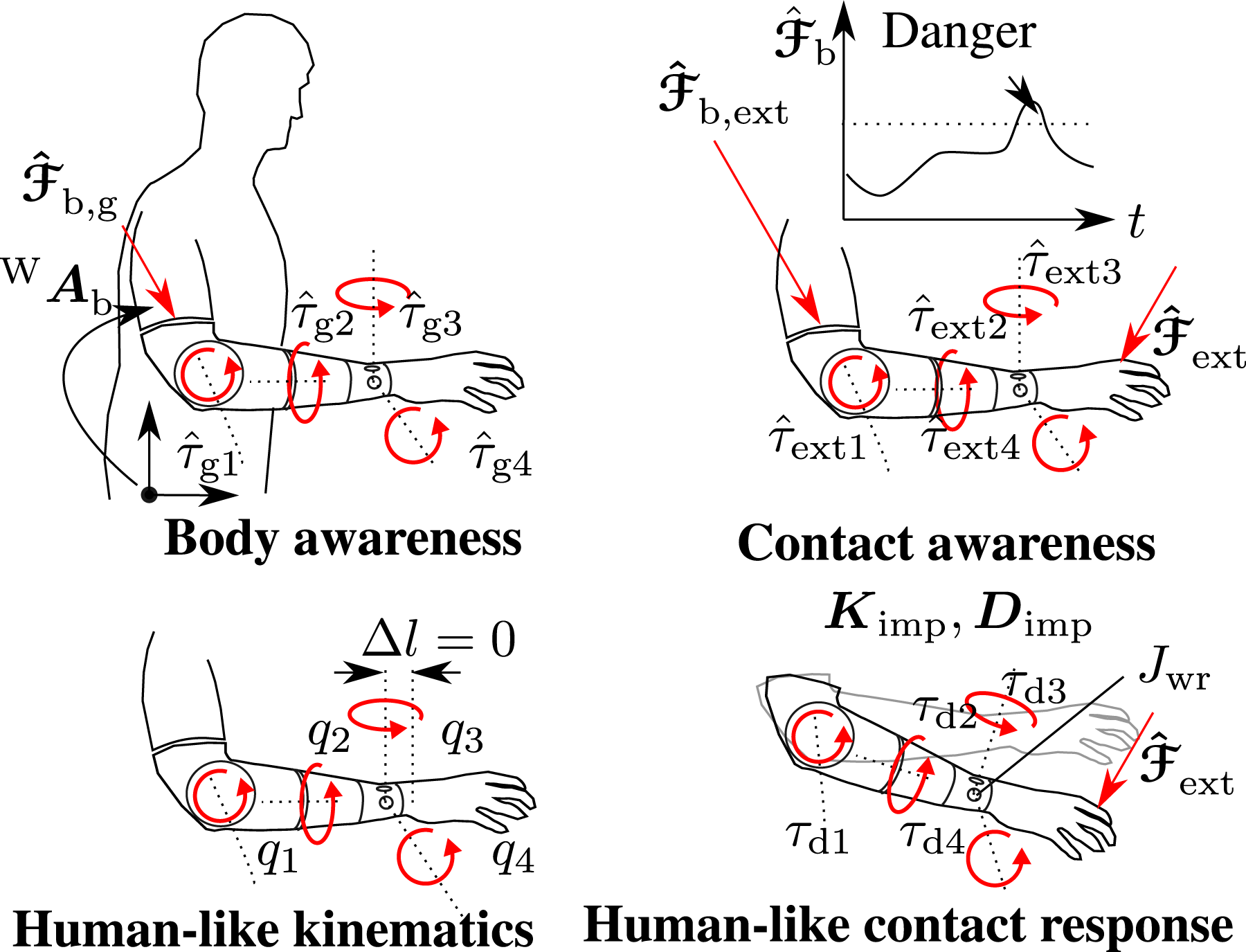
These challenges require a fundamental reconsideration of design tools in prosthetics: 1. A novel design paradigm for the development of human-like prostheses is necessary, which governs how to design technical components in relation to the human body. 2. New technological approaches and engineering tools are needed, as new functionality shall be integrated into the wearable device without making significant compromises on size, weight, torque-density and degrees of freedom.
The novel design paradigm is used for identifying corresponding working principles between the human body and the artificial prosthesis (i.e., in mechanical structures, sensors, actuators, controllers, and device intelligence). Our working hypothesis is that a human-inspired prosthesis, developed along the principles of the human body, also provides human-like behavior. This hypothesis shall be validated in this work based on the feature requirements listed in Figure 1.
The novel technological approach is to utilize mechatronics and controllers from soft and tactile (Albu-Schäffer et al., 2007a; Haddadin et al., 2022; Hirzinger et al., 2002) and humanoid robotics (Englsberger et al., 2014; Hyon et al., 2017), as these provide powerful solutions for complex robotic systems and active compliance control.
The novel engineering tool for the development of the ANP is a complete mathematical model of the robotic device and its controllers, realized in a digital twin simulation. This allows us to forecast the robot’s physical behavior and to optimize its components in a small-size design, despite the novel capabilities and components, which are introduced in the hardware design.
In the following, the state of the in upper-limb prostheses and the background in human motor control is discussed, before outlining the contributions of this work.
1.1. State of the art
1.1.1. Prosthesis design
Different design strategies have been followed in arm prosthetics with the aim of providing the best user experience for the amputee. Usually, the aim is a balance between functionality, weight, and size. Typical requirements for the design of a mechatronic prosthesis include high payload at high Load-to-Weight ratio (Lenzi et al., 2016) and human-like appearance (Ottobock, 2021) (i.e., human-like kinematics, motion, size and texture)—all of which reflect fundamental capabilities of the human body. A key factor for achieving small, lightweight actuators with high output torque is the use of electromechanical actuators combined with high gear ratios (Johannes et al., 2020; Lenzi et al., 2016; Weir et al., 2008). First, let us consider commercial transhumeral prosthetic devices.
1.1.2. Commercial prostheses
Typically, commercial transhumeral prostheses are equipped with an active elbow for flexion-extension (F/E), a single active dof in the wrist for supination/pronation (S/P) (and possibly one additional passive wrist dof), and a modular hand. Examples for commercial devices are: the UtahArm and Wrist Rotator by Motion Control (Motion Control, Inc., Salt Lake City, Utah, USA) (Fillauer, 2021), the Dynamic Arm and Michaelangelo Hand/Wrist by Ottobock (Ottobock SE & Co. KGaA, Duderstadt, Germany) (Ottobock, 2021), the Boston Digital Arm (Liberating Technologies Inc., Hollison, MA, USA) (Liberatingtech, 2021), and the Touch Bionics iLimb Wrist (Ossur hf, Reykjavic, Iceland) (Ossur, 2021).
Devices with flexion-extension (F/E) of the wrist include the KS-Bionic Hand by Kesheng Prostheses (Shanghai Kesheng Prosthetic Technology Co., Shanghai, China) (Keshen, 2021) and the Powered Flexion Wrist by Fillauer Motion Control (Fillauer Europe AB, Sollentuna, Sweden) (Fillauer, 2021). In contrast to the aforementioned systems, for which wrist modules cannot be combined with S/P, the LUKE Arm (Mobious Bionics LLC, Manchester, NH, USA) (Mobius bionics LLC, 2021) has this ability.
1.1.3. Research prostheses “elbow to wrist”
A transhumeral prosthetic system with a 1-dof wrist (S/P) and a 1-dof elbow (F/E) was proposed in (Bennett et al., 2016). The work focuses on a mechanical design solution that provides backdrivable elbow actuation and fits into an anthropomorphic forearm model. A transhumeral prosthetic system with a 2-dof wrist (S/P, F/E) is the Luke Deka arm. The modular prosthesis, also containing a hand, is distributed by the company Mobius Bionics LLC and is available for shoulder, humeral and radial amputation. A prior research variant of that system was proposed by Resnik et al. in (Resnik et al., 2014). Another highly advanced prosthetic system with a 2-dof wrist (S/P, F/E) and hand is the Rehabilitation Institute of Chicago (RIC) arm (Lenzi et al., 2016). The system consists of a 3-dof arm and a 2-dof hand. The focus of the RIC arm lies in providing miniaturized mechatronics for small form factor without sacrificing degrees of freedom and functionality. This was achieved by compact mechatronic design solutions and high gear ratios. Despite the multi-stage gears, high efficiencies were achieved. The modular prosthetic limb (MPL) is the first reported full transhumeral system with a 3-dof wrist with additional R/U deviation. It also includes a 10-dof hand (Bridges et al., 2011; Johannes et al., 2011, 2020). The goal of this project was to develop a cutting-edge prosthetic arm with human-like kinematics, torque and sensory feedback in an anthropomorphic form factor. In fact, the MPL is the first and only reported system apparently utilizing torque sensing and impedance control, although to the best of the author’s knowledge, these capabilities have not yet been demonstrated in public. The MPL joints use multi-stage gears consisting of cycloid and planetary gears in order to obtain high torques, thus are similar to the concept of the RIC arm. The modular wrist consists of a serial RRR kinematics with a human-like form factor, similar to (Lenzi et al., 2016; Weir et al., 2008). The motor for F/E is implemented in the palm of the hand.
Other related areas to our contribution, such as the background in stand-alone prosthesis wrists, prosthetic human machine interfaces, soft and tactile robotic technology may be found by the interested reader in Section A in the Appendix. In the following, we investigate the background in human neuromechanics to better understand our contribution.
1.2. Human neuromechanics
1.2.1. Motor control
The human motor control system is characterized by relatively precise movement independent of both body orientation with respect to gravity (Carvalho et al., 2008) and visual perception (DiZio and Lackner, 2000; Franklin et al., 2007). Humans are also able to perceive and respond to contact forces, regardless of where along the body the contact occurs. They can distinguish contacts by comparing expected and measured signals (Wolpert and Flanagan, 2001). Furthermore, human limbs exhibit accurate compliant behavior during physical interaction with the environment. In fact, the muscle impedance can be modulated—a skill which is used by humans for learning new motor tasks and compensating for uncertainties (Burdet et al., 2001; Franklin et al., 2007).
1.2.2. Neuromechanics
The musculoskeletal system is tendon-driven with very low friction and inertia (Amadio, 2013; Bartz et al., 2019), which corresponds to high-performance backdrivability in mechanical terms. A multi-modal sensory system provides a wide range of information about the external world and the state of the body, even without considering the sense of vision, see Figure 2 (left). Muscle spindles and the Golgi tendon apparatus, which are integrated in the muscle fibers and tendons, respectively, provide sensory feedback on muscle length, speed of stretching, and proprioceptive force. A wide variety of tactile sensors in the skin provide detailed information about contact points, pressure, and texture. The vestibular system senses body orientation relative to gravity. The ANP mimics key components of the human neuromuscular system. The figure compares functional technical and biological modules for the human and the ANP.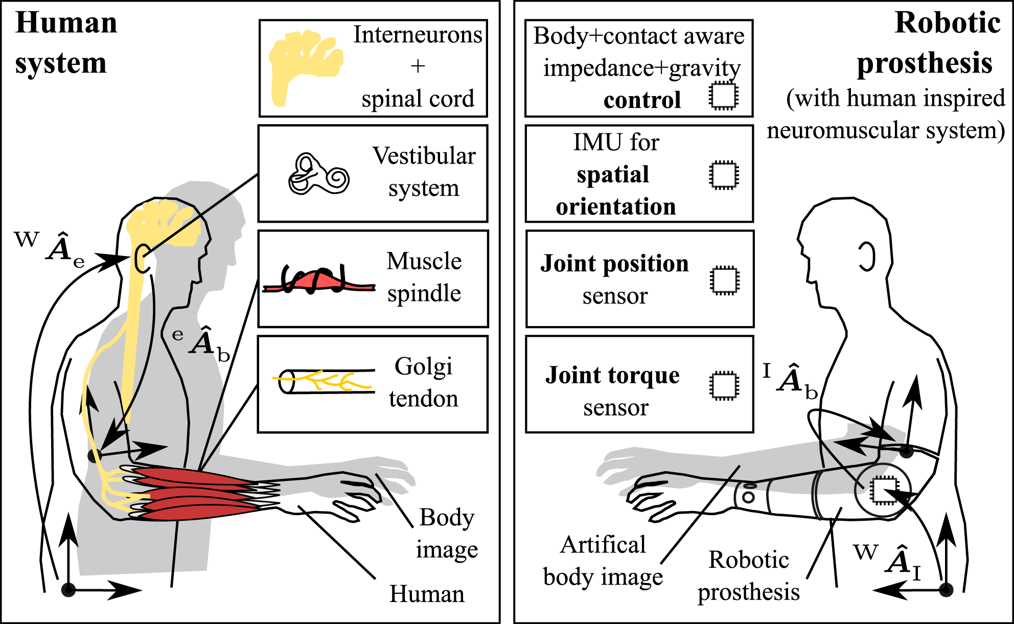
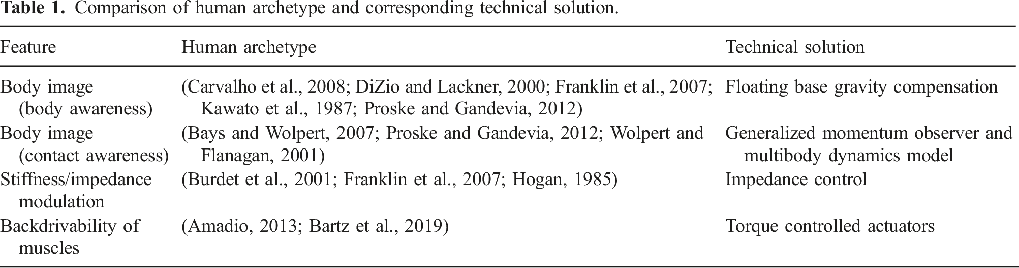
In the central nervous system (CNS), the cerebellum, the primary motor cortex, and the spinal cord, are mainly responsible for complex motor control and learning, including adaptation to novel dynamics (Milner and Franklin, 2005). It is believed that this is achieved by learning an internal (inverse) dynamics model of the self and of the environment, which may be referred to as a “body image” (Kawato et al., 1987; Proske and Gandevia, 2012), see Figure 2 (left). Thus, the human does not rely on reactive feedback control only, but is able to deliver predictive feed-forward motor commands (Krakauer et al., 1999). Internal models are also used to detect contacts based on proprioceptive sensory information by comparing the expectation from the internal model with the measured signal (Wolpert and Flanagan, 2001). Furthermore, human motor control can be described as a form of impedance control (Burdet et al., 2001; Hogan, 1985). In summary, Figure 3 (left) gives a system-level overview of human neuromechanics that is most relevant for this work. Table 1 depicts a summary of capabilities, provided by the human archetype, and where these may be found in literature. The interested reader may find more details about the human anatomy in Section A in the Appendix. In the following, we present the contribution of this work. The technological approach of the ANP is directly inspired by the principles of human motor control. The left image is a modified version from (Sensinger and Dosen, 2020) and was extended accordingly. *In the terminology of automatic control it is rather a compensation. Comparison of human archetype and corresponding technical solution.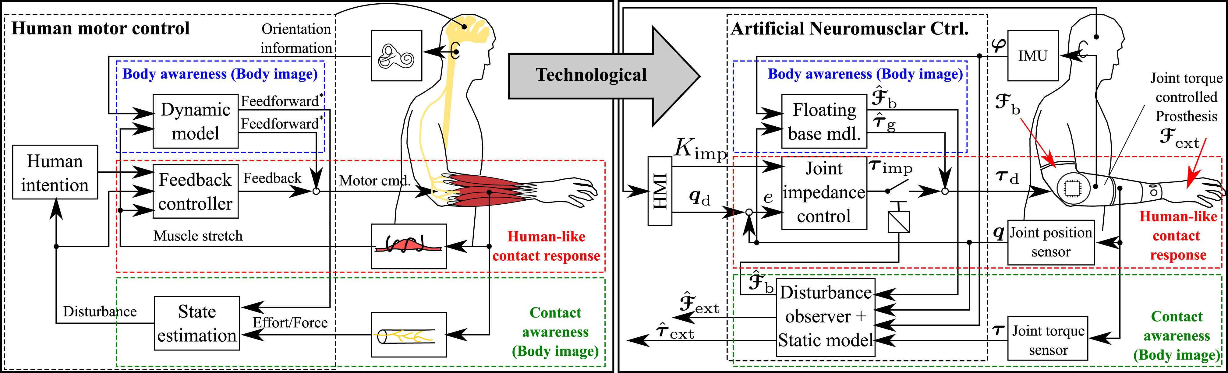
1.3. Contribution
1.3.1. Capabilities
In this work, based on our previous work in Kuehn et al. (Kühn and Haddadin, 2017), we introduce a novel prosthesis paradigm that is systematically inspired by the fundamental design and control properties of the human neuromuscular system. Specifically, the design concept was grounded in sensors, actuators and controllers, which have a direct biological correspondence to the human body, see Figure 2.
The body image (Kawato et al., 1987; Proske and Gandevia, 2012) essentially reflects the kinematic and dynamic model of the human. For the ANP, we propose an artificial body image reproducing its key functionalities.
1
While the human can determine its body orientation
We define body awareness as the ability of the prosthesis • to calculate its floating base kinematics • to compute the model-based joint torques • to utilize
Consequently, the prosthesis maintains its angular positions • an external wrench • its effect • and its effect • to render linear joint stiffness and damping according to • to render backdrivable actuation
3
for the case of
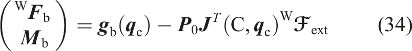
For the case of no contact wrench,
We define human-like kinematics as the ability of the prosthesis to render the human elbow to wrist kinematics in terms of the joints degrees in elbow (F/E) and wrist motion (F/E, R/U, and S/P).
Finally, Table 1 lists the artificial technical solutions of the ANP and compares them to the related biological capabilities in the human body.
1.3.2. Design paradigm
The aforementioned capabilities require accurate numerical multi-body models and advanced mechatronic solutions. In this work, we introduce a sim2real-guided development approach for upper limb prostheses, which enables the design of such a next generation prosthesis, with close to human-like size, weight and human-like capabilities—in just a single hardware prototype iteration. Based on a digital twin simulation of the prosthesis, a stack of simulative tests is performed to validate all desired capabilities from Figures 1 and 2 and to gain information for component choice and dimensioning, which is then used for elaborating the geometries. Once all tests are successful, the device is built and validated in experiments.
1.3.3. Mechatronics
Key capabilities of the ANP mechatronics, see Figure 4, are (i) the torque-controlled robot joints, (ii) the 4-dof kinematics and (iii) an IMU which measures the orientation of the device for internal models in realtime. On this basis, floating base dynamics, extended momentum observation, and joint-level impedance control are combined within our novel Artificial Neuromuscular Controller, see Figure 3 (right). The included wrist provides a tendon-driven mechatronic solution to bring high-performance torque sensing to upper limb prosthetics.
4
The wrist includes human-like kinematics due to the coinciding joint axes (i.e., Δl = 0, see Figure 1) and a particularly low inertia of movable parts (mwr = 28 g, all diagonal tensor entries Jwr < 240 g cm2), ensuring high mechanical transparency. Thus, the full prosthesis is a hybrid tendon-/non-tendon-driven system. These advanced capabilities are provided in a compact, wearable transhumeral prosthesis with a weight of 1.7 kg without hand and battery. Mechatronic solution of the ANP with the modular Softhand Pro 2.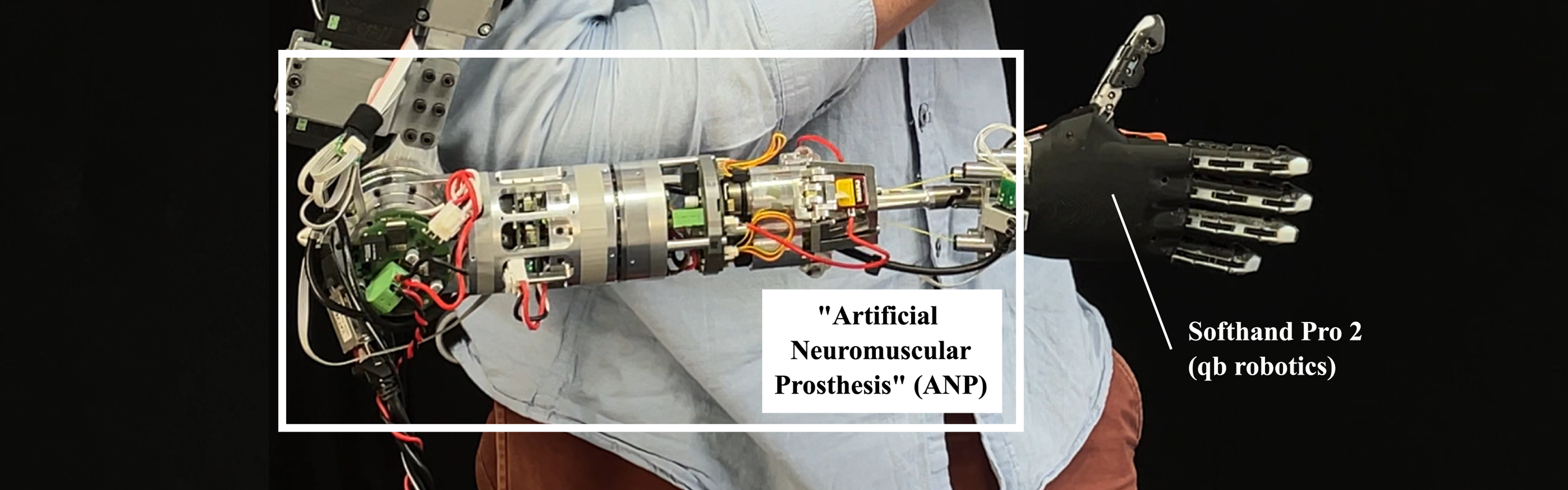
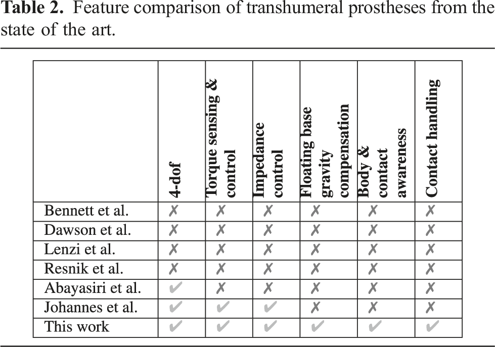
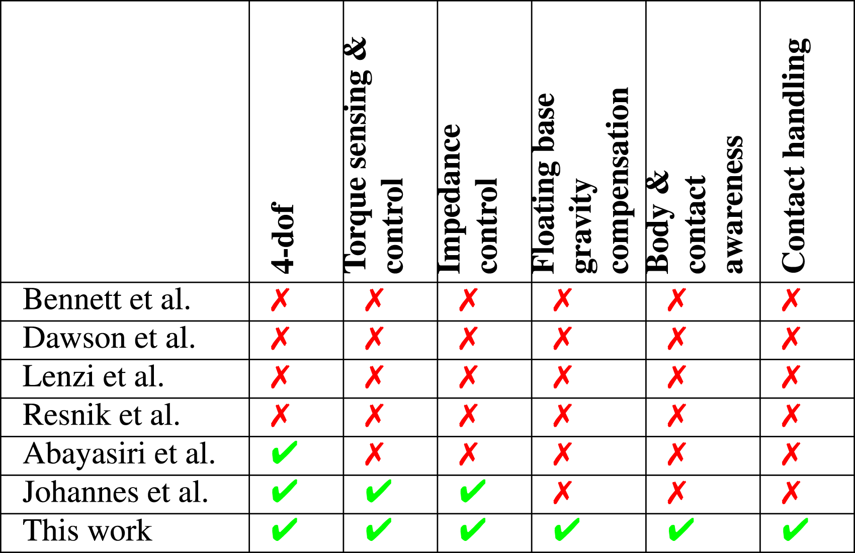
1.3.4. Comparison
Feature comparison of transhumeral prostheses from the state of the art.
1.3.5. Summary
In summary, the core contributions of this paper are: • I) Capabilities: re-creation of the human neuromuscular system for upper-limb prostheses in terms of body awareness, contact awareness, and human-like contact response (according to definition) providing a human-inspired system behavior, or in other words, a joint-torque-level device autonomy. • II) Mechatronics: the Artificial Neuromuscular Prosthesis ANP with 4-dof human-like kinematics, full joint torque sensing, IMU, small size and a weight of 1.7 kg (without hand and battery), which emulates the human neuromuscular system in terms of – multi-modal sensing
5
and an internal (floating base) model to enable full body and contact awareness, – human-like motion and contact response behavior via active backdrivability, (adaptable) impedance control and (floating base) gravity compensation. • III) Design paradigm: the first prosthesis which was developed in a human-inspired and sim2real-guided design paradigm providing a blueprint for the next generation of robotic prostheses. • In addition, a hybrid tendon/non-tendon-driven joint torque mapping, leading to a hybrid tendon-/non-tendon driven joint impedance controller.
Control and interaction modes—new to the prosthesis world—are enabled through this design: the ANP provides floating base teaching, in combination with the guidance via interaction forces, as an alternative human machine interface. Body and contact awareness may be used to monitor the vulnerable stump prosthesis connection and to introduce a protective control mechanism. Finally, all methods are validated in simulation and experiments.
The remainder of this paper is structured as follows: Section 2 presents the sim2real-guided design process and discusses the requirements for the development. Section 3 proposes the mechatronic solution of the ANP. The modeling and control of the ANP are shown in Section 4 and Section 5. Experimental results can be found in Section 6 (and the associated simulation results in Section F in the Appendix). The paper is discussed in Section 7. The paper is concluded in Section 8.
2. Design process
In this section, we introduce a so called sim2real-guided design process for upper-limb prostheses. By this, we aim to systematize, formalize and simplify the definition, design, simulation/experimental evaluation of upper-limb prostheses. In this context, also related simulation-based design approaches for general mechatronics and robotic systems (Broenink et al., 2010; Kelemenová et al., 2013; Kellner et al., 2015; Mattingly et al., 2012; Qamar et al., 2011; Zhou and Broenik, 2017) may be mentioned, showing that (also incorporating the insights from the state of the art) a gap for a holistic simulation-based development approach in prostheses and even (force-sensitive) robotic systems exists. The key idea of the sim2real-guided design is a time-domain physics simulation of the prosthesis. This simulation aims to reproduce the full physical behavior of the prosthesis in form of a digital twin—similar to a real device but virtually simulated on a computer. As a comparison: in a traditional design, see Figure 5, the prosthetic device is computed and designed along a couple of extreme cases (e.g., maximum load, acceleration, speed and deflection) which are usually derived from simplified models. At this stage, higher-order, dynamic and nonlinear effects are typically neglected and three dimensional problems are simplified to quasi-static two dimensional ones. The benefit of this approach are small and handy algebraic equations which can be easily evaluated (e.g., in a spreadsheet). As a downside, such a traditional design requires a-priori valid assumptions, simplifications and experience. Due to many simplifications, there remains a high risk for systematic errors and thus the need for an increased number of hardware prototypes. Due to these limitations, we instead follow the sim2real-guided design process with a digital twin simulation of the prosthesis, see Figure 5. Rather than solving simple case-dependent algebraic equations, we perform holistic modeling with all known relevant physical effects of the prosthesis and then perform numerical simulations by solving the nonlinear differential equations of the prosthesis including its full control stack via numerical integration. Instead of evaluating extreme cases only, we interact with the device via trajectories, loads, and interaction forces as in reality and then obtain the admissible values based on the set of all simulated time-steps, for example, by taking their maximum. This approach allows for a versatile evaluation of the device and also provides working controllers. Consequently, by using this approach, many physical effects, including their coupling and dynamics, are considered. The process requires less intuition and experience, is more systematic, reduces the chance for systematic errors in prosthesis design, and thus the number of prototypes (cost, effort and time). Comparison of traditional versus sim2real-guided mechatronics design to determine admissible loads, explained by the following illustrative and simple example: in the traditional design, a maximum admissible force Fmax may be determined by an equation 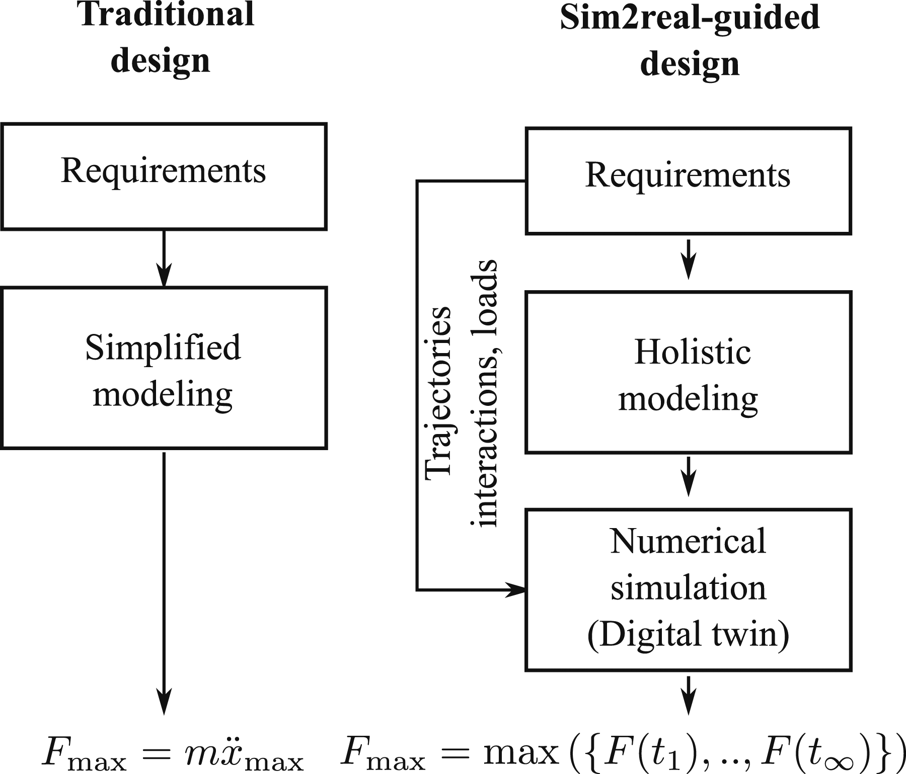
Figure 6 shows a detailed scheme of such a sim2real-guided design process. The figure is essentially a flow chart and shows the particular steps of the development process including the flow of information (dotted lines). Based on the initial concept from Figures 1–3, the requirements of the prosthesis (i.e., Functional requirements F, Technical requirements T and Specification S) are derived first. Then, a conceptual approach of the prosthesis is elaborated, which includes the kinematic, transmission, sensor and actuation concept. On this basis, a model and control approach is developed which is implemented in a numerical simulation. Disturbing effects such as friction or uncertainties are not considered in the model but may be easily included into the process.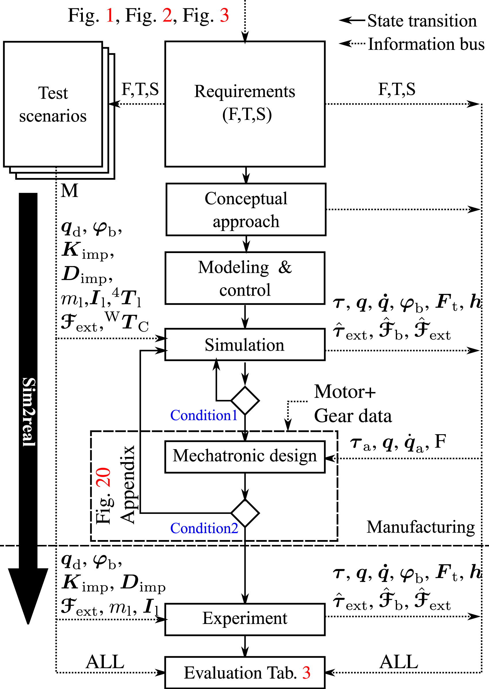
This time-domain simulation plays a key role in the sim2real-guided design process as it provides information about the feasibility of the control concept and about loads acting on components and structure. More specifically, test scenarios are defined which translate the requirements F, T and S into input trajectories, parameter sets, interactions and test metrics M for simulation and experiment. These test scenarios are essentially a batch of all tests which the prosthesis should fulfill in simulation and reality. The simulation is considered successful if all conditions, referred to as Condition1, are fulfilled for the full stack of test scenarios, see Figure 6. This means, the full Artificial Neuromuscular Controller, see Figure 3, should work together with the plant model in simulation which is verified as follows: impedance control is validated by the residuum
In the next step, the mechatronic design is elaborated. This process includes the choice of suitable components (i.e., gears and motors) which provide sufficient performance to realize all simulated values of
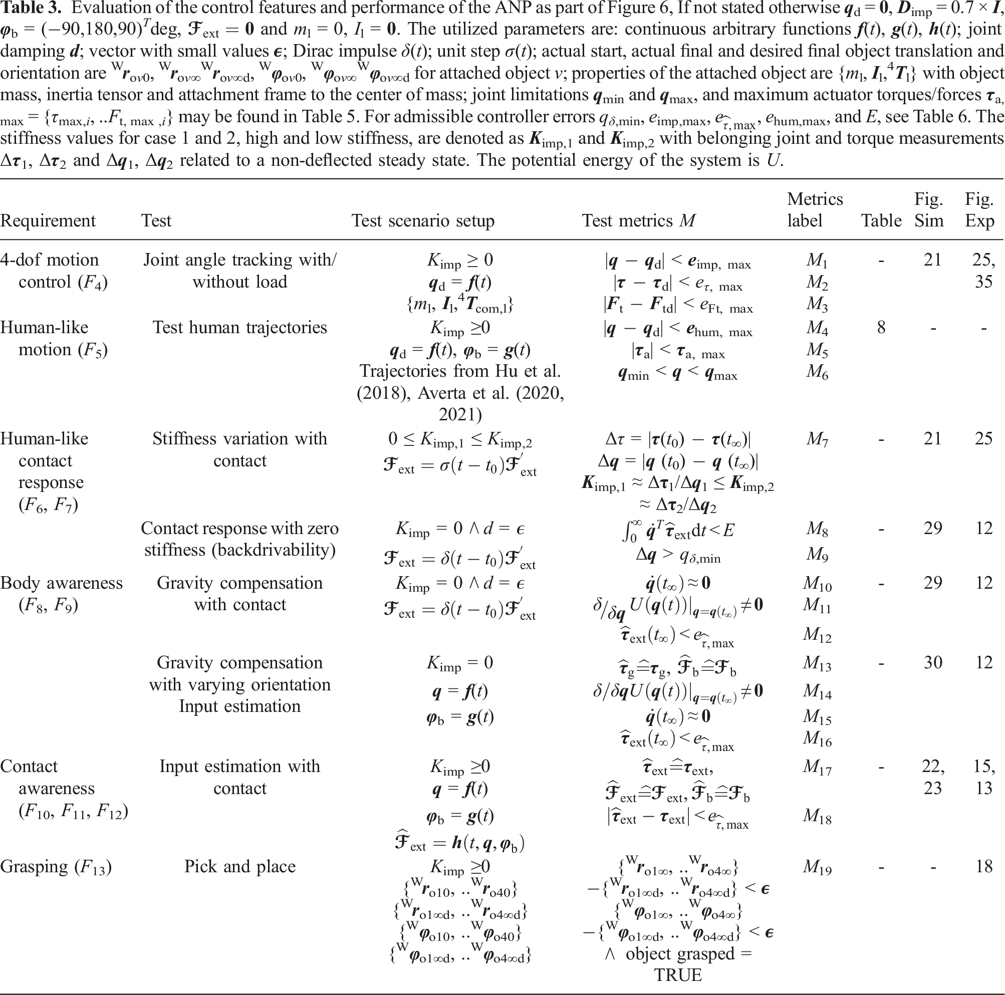
Evaluation of the control features and performance of the ANP as part of Figure 6, If not stated otherwise
In conclusion, the proposed sim2real-guided design process combines the power of a numerical physics simulation with a structured rule-based development to realize an upper-limb prosthesis in a single prototype iteration only.
2.1. Requirements
In the following, functional F and technical requirements T as well as specifications S, from Figure 6, are defined. These complex requirements and specifications shall be achieved by the design solution, simulation and experimental results, as described below.
2.1.1. Functional requirements (F) - mechanics
A transhumeral prosthesis with a 3-dof wrist (F/E, R/U, S/P), not including the hand, is to be developed (F1). In addition, a modular hand shall be attachable at the wrist (F2). The prosthesis is wearable by both unimpaired subjects and individuals with a transhumeral amputation. For healthy subjects, the device shall be attached at the center of the upper arm (humerus) via 3D-printed components and Velcro fasteners (for testing reasons). For users with a transhumeral amputation, the device should be worn by a stump interface in future versions (F3).
2.1.2. Functional requirements (F) - control
The device should provide 4-dof motion control from elbow to wrist which shall be realized by an active compliance controller, controlling force/torque and motion (F4). More specifically, the prosthesis shall be capable of reproducing real everyday human motion, defined by the human data from Hu et al. (2018), Averta et al. (2020, 2021), as closely as possible (F5), which shall be validated by a physics simulation of the prosthesis considering its maximum capabilities. The joints of the prosthesis should imitate human muscles in the sense of contact response, joint stiffness and backdrivability (F6). In gravity compensation, guidance of the device solely via interaction forces shall be possible (F7). The device shall have a body image/body awareness, including the floating base kinematics and robot dynamics of the mechanical system. This should include the awareness of joint torques and base reaction forces/moments at the prosthesis attachment affected by gravity and orientation (F8). By this approach, the ANP should be able to compensate its own weight during arbitrary operation (F9). The device is to be equipped with a contact recognition which estimates the magnitude of the wrench distal from the wrist (F10). With this method, the device can quantify the effect of the contact wrench on the prosthesis base and the residual in the form of base forces and moments (F11). In addition, the device shall be equipped with a protective control mechanism to a safe mode (e.g., to gravity compensation) if contacts induce excessive base moments (F12). Reaching, grasping and placing objects of Activities of Daily Life (ADL) shall be possible (F13).
2.1.3. Technical requirements T
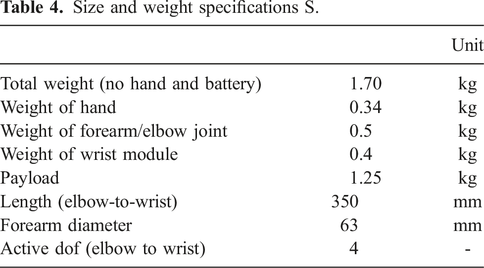
Size and weight specifications S.
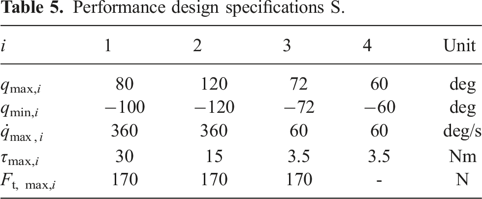
Performance design specifications S.
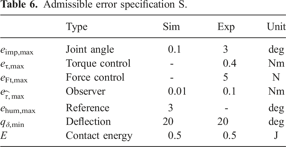
Admissible error specification S.
In the following, we describe the mechatronic solution of the transhumeral arm prosthesis.
3. Mechatronic solution
The ANP consists of four active degrees of freedom as elbow (1-dof), forearm rotation (1-dof), wrist (2-dof) and additionally a modular 1-dof hand. Figure 7(a) depicts an exploded view of the system. It consists of a robotic Elbow joint and a Forearm joint (of the same size and type). Both are interconnected by a Rigid structure. These are followed by the Wrist module. The ANP was designed to attach a modular hand. Here, the Softhand Pro 2 (Della Santina et al., 2018) is attached to the device. Figure 7(b) provides an overview of the system, its dimensions and coordinate frames. All modules of the prosthesis were custom-made out of Aluminium EN AW 7075. All custom geometries were realized by Computerized Numerical Control (CNC) milling. Specially stressed geometries have been optimized to the defined loads by a finite element analysis (FEA), see Figure 33 in the Appendix. System design of the ANP including mechanical design and software structure.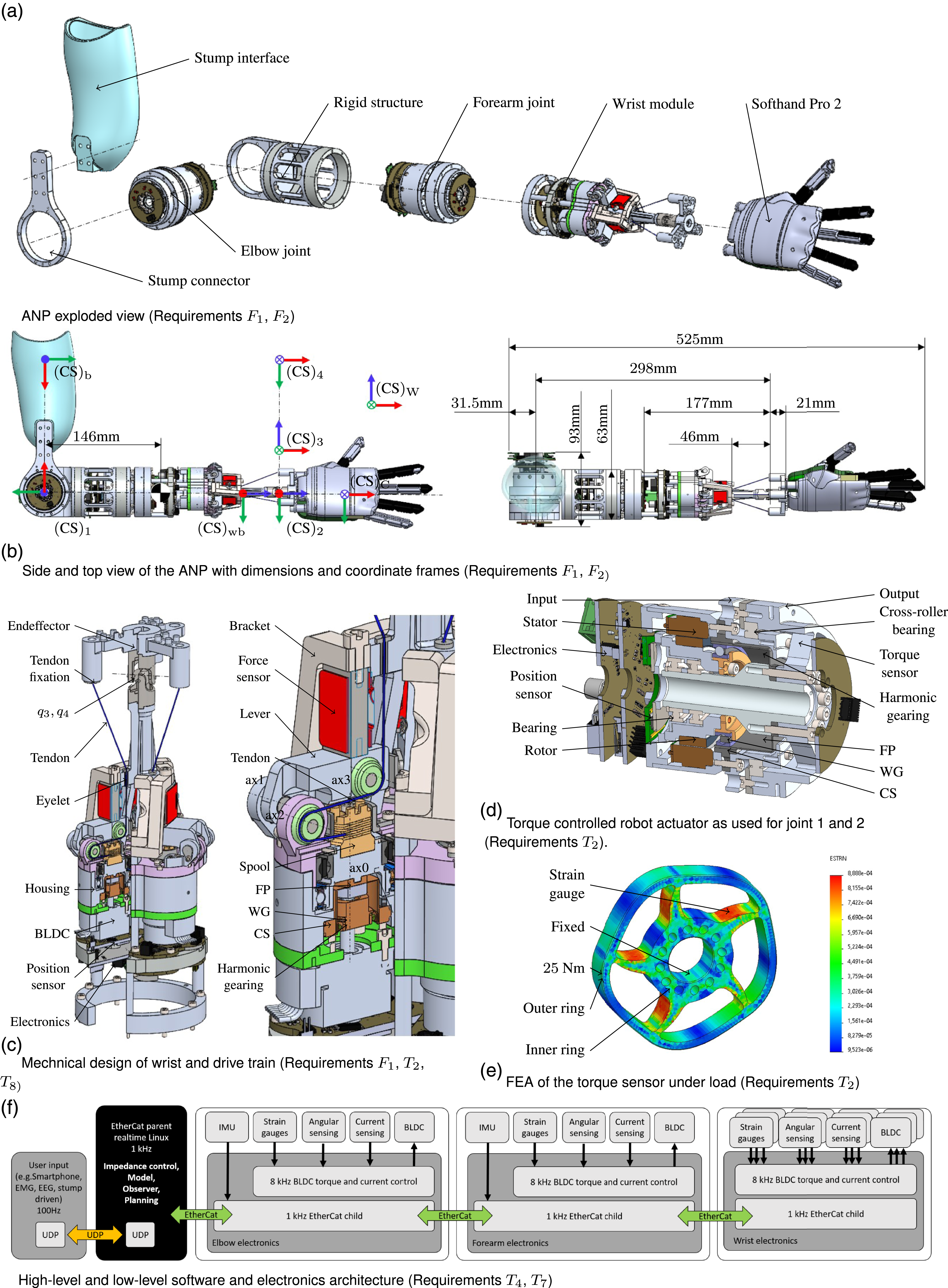
The electronics architecture and software structure are depicted in Figure 7(f). A control personal computer (PC) (x86) runs the high-level control routines on a Ubuntu 16.04 hard realtime system with Matlab/Simulink (MathWorks, MA, USA) at 1 kHz. The control PC, which is the EtherCat Master, communicates with the actuators (EtherCat Slaves) in realtime. Elbow, forearm and wrist run with individual custom-made PCBs and control software. These provide field oriented current control (PI) in a cascade with a P torque controller at 8 kHz. Additionally, IMU measurements are provided by the elbow and forearm electronics over the EtherCat protocol in realtime. Finally, all actuator dof provide motor side joint position and link side joint torque measurements. The prosthesis desired joint motion
All prosthesis modules run at 24 V. Typical current consumption is 0.7 A in idle mode, that is, holding position in impedance control, and up to 1.4 A for the payload experiments shown in this work. In the following, the mechanical design of the ANP wrist and forearm/elbow are elaborated in more detail.
3.1. ANP wrist
Figure 7(c) depicts the mechanical design of the wrist based on the kinematics shown in Figure 9. The advantage of such a design is the lightweight and space-saving joint design at the intersecting joints, as torque, position sensing and actuation are placed remotely. The wrist consists of three point symmetric actuator modules, each driving one of the three tendons, respectively. As the tendons enter the Eyelet, they are guided via two Pulleys at ax2 and ax3 to the Spool, see Figure 7(c). A Harmonic gearing (ig = 100, τg,max = 1.4 Nm, ng,max = 10000 1/min, no load starting torque τmax = 3 mNm) drives the Spool (rs = 3 mm) and amplifies the motor torque of the brushless DC motor (BLDC, τm,N = 10 mNm, nm,max = 10000 1/min) lying on axis ax0. According to Figure 20 in the Appendix, the smallest available gear variant, with the highest gear ratio and the smallest motor, was chosen. Wave generator (WG), circular spline (CS) and flex spline (FP) of the harmonic gearing are used in the configuration driving, fixed, driven.
The tendon force measurement is based on the novel mechanism shown in Figure 8. A linear strain-gauge based Force sensor (Fs,max = 440 N, accuracy of 0.1% of Fs,max) is located between a Bracket and a movable Lever. The tendon force Ft affects the resulting force F
s
= lt/lsFt in the force sensor where lt and ls are the distances from the bearing axis ax1 to the force Ft and Fs, respectively. The output signal of the Force sensor is amplified and measured by a 16-bit analogue-digital converter. A 14-bit magnetic Position sensor (accuracy ± 1.8°deg) measures the motor angle at the bottom of the BLDC, where low-level Electronics for motor control and strain gauge amplification are also located. The tendons are 0.4 mm thick, made of Dyneema, and provide a break force of 360 N. A maximum tendon force of 170 N was measured. Lever mechanism for measuring the tendon force in the wrist module (Requirement T2).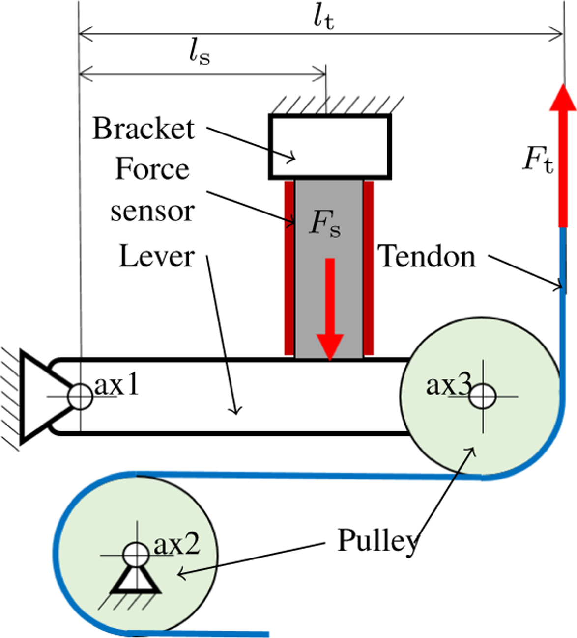
3.2. ANP forearm and elbow joint
Elbow joint and forearm joint of the prosthesis are realized by the robotic actuator from Figure 7(d). The actuator was custom-made as no device on the market could meet the specifications from Tables 4 and 5. A suitable brushless direct current (BLDC) motor kit (τm,N = 0.25 Nm, nm,max = 6000 1/min) and a harmonic gearing (ig = 100, τg,max = 30 Nm, ng,max = 6000 1/min) were chosen by following the procedure from Figure 20 in the Appendix. However, the initial combination of the smallest gear and smallest motor did not lead to a feasible mechanical design. Consequently, larger variants were chosen, which still fit within the demanded forearm diameter, see Table 4. As a consequence, the maximum torque of the joint τm,Nig ≈ 25 Nm became larger 6 than the maximum simulated actuator torque max (τa(t)) ≈ 8 Nm for lifting the simulated payload of 1.25 kg. The joint includes a custom-made joint torque sensor, see Figure 7(e). It consists of five spokes inspired by the designs in (Lee et al., 2014; Schiele and Hirzinger, 2011). Four strain gauges were placed at the location of maximum positive and negative deflection (red color), caused by compression and bending, on the upper and lower side of each spoke. The strain gauge signals are amplified and measured by a 16-bit analogue-digital converter. The motor position is measured by a 16-bit encoder (accuracy 0.05 deg). Brakes are omitted to save additional weight.
4. Modeling
In this section, we present a complete dynamic model approach for upper limb prostheses. We subsequently use the prosthesis model for plant modeling, advanced body and contact aware algorithms, as well as for feed-forward control. We first present the floating base robotics model, including contact forces and moments acting on the ANP, and then describe how the tendon-driven wrist is integrated into the complete model structure. We model the prosthesis interaction to the residual limb of the human by a 6-dof spring-damper system which provides the reaction forces and moments for our complete plant modeling.
4.1. Floating base dynamics
Essentially, the ANP can be modeled as a serial kinematic structure which is described by its generalized joint coordinates 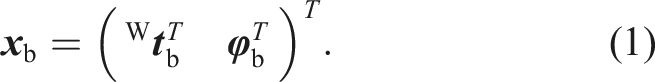
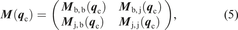
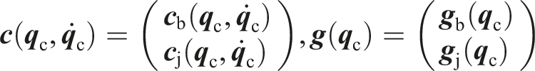
The matrix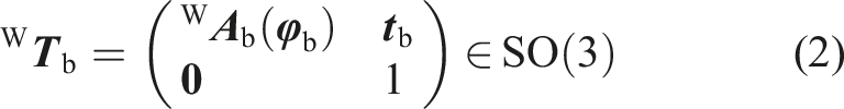

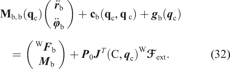
The dynamic floating base model of the prosthesis is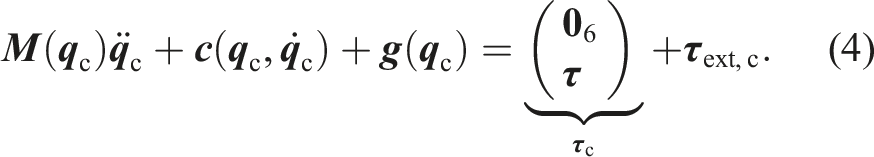

Two types of contacts are considered for the prosthesis summing up to the generalized total forces

The fixation of the floating base prosthesis to the human is modeled as a spring-damper system. The location of the floating base coordinate frame (b) is assumed to correspond to the attachment point between human residual limb and prosthesis, see Figure 7(b). Let us assume the position and orientation of the human residual limb to be expressed by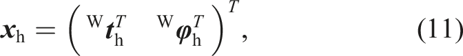


4.2. Tendon actuation
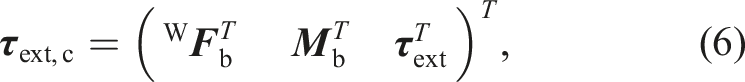
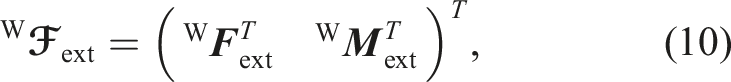
Even though the prosthesis is finally controlled in joint space, the wrist is locally controlled in tendon space via tendon-level force controllers. This requires back and forth transformations from joint to tendon space and vice versa, see Figure 9(a). As the wrist consists of the last two rotational joints q3 and q4 of the structure, see Figure 7(b), the wrist coordinates Tendon modeling and control. (a) Tendon-joint mappings for the 3SPS-1RR wrist. (b) 3SPS-1RR kinematics of the wrist.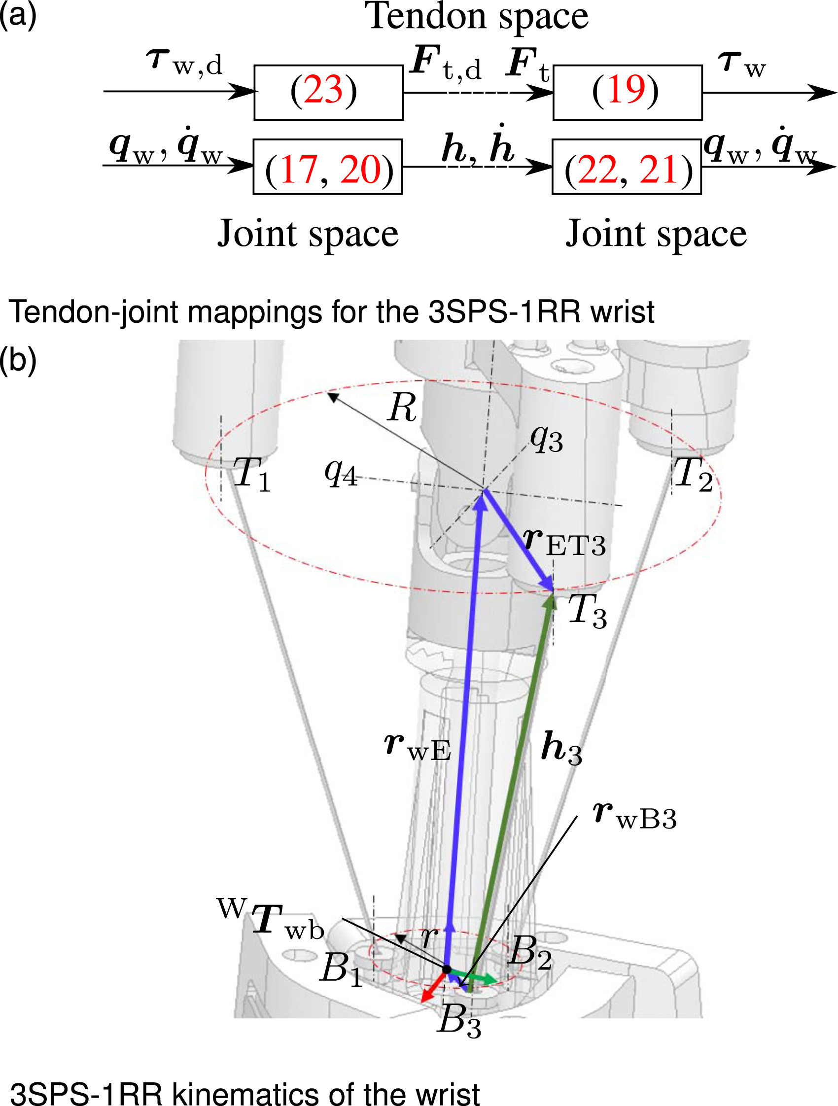
The ANP wrist of the prosthesis can be classified as 3SPS-1RR tendon driven parallel kinematics with S, P, R representing spherical, translation and rotational degrees of freedom. The preceding number (3) denotes the number of serial chains, consisting of a spherical, prismatic and spherical degree of freedom (SPS). These are in parallel to two rotational joints in series (1RR), see Figure 9.
The system is driven by k = 1..3 tendons which are attached at T
k
to the endeffector and pass the eyelets B
k
. Both T
k
and B
k
are equally distributed on circles with radius r and R, respectively. T1 and B1 lie on the same plane spanned by y and z of frame W
Despite the parallel kinematics of the wrist, the prosthesis can still be expressed as serial chain kinematics as if the tendons are considered massless. However, nonlinear mappings for kinematics and static force/torque relations are required. Following (Murray et al., 1994), the extension function, or inverse kinematics of the wrist


The relation between wrist joint torque 
The relation between wrist joint velocity 
In the following, the tendon length
The direct kinematics can be computed at each control cycle based on a given tendon length 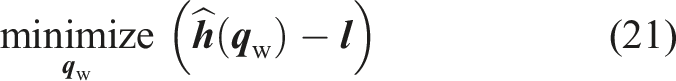

The desired tendon forces 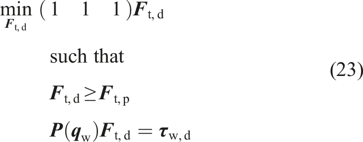
By defining the actuator coordinates of the whole prosthesis to
5. Control
The two main control methods in the prosthesis are a fully fledged joint impedance controller and a floating base generalized momentum observer, that is, well established methods from soft and tactile robots, yet not established in upper limb prosthetics.
5.1. Joint impedance control
The prosthesis is controlled by the standard joint impedance controller


5.2. Momentum observation
The generalized floating base momentum observer

With this basis, the algorithms for body and contact awareness can be built in the following.
5.3. Body and contact awareness
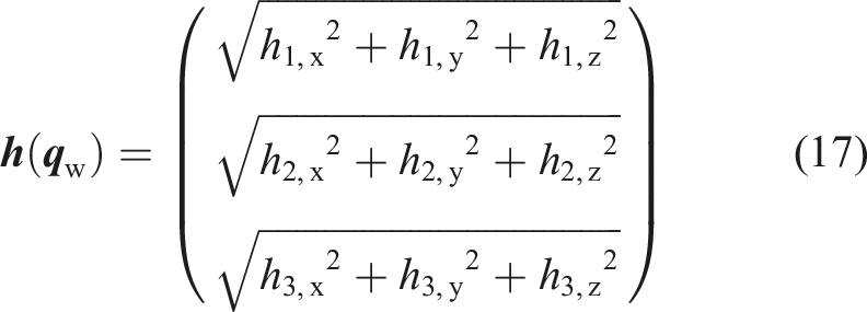
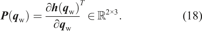
In the following, a model is derived which is then used for computing the contact wrench Schematics for wrench calculation at the prosthesis base, attached to the human body, with 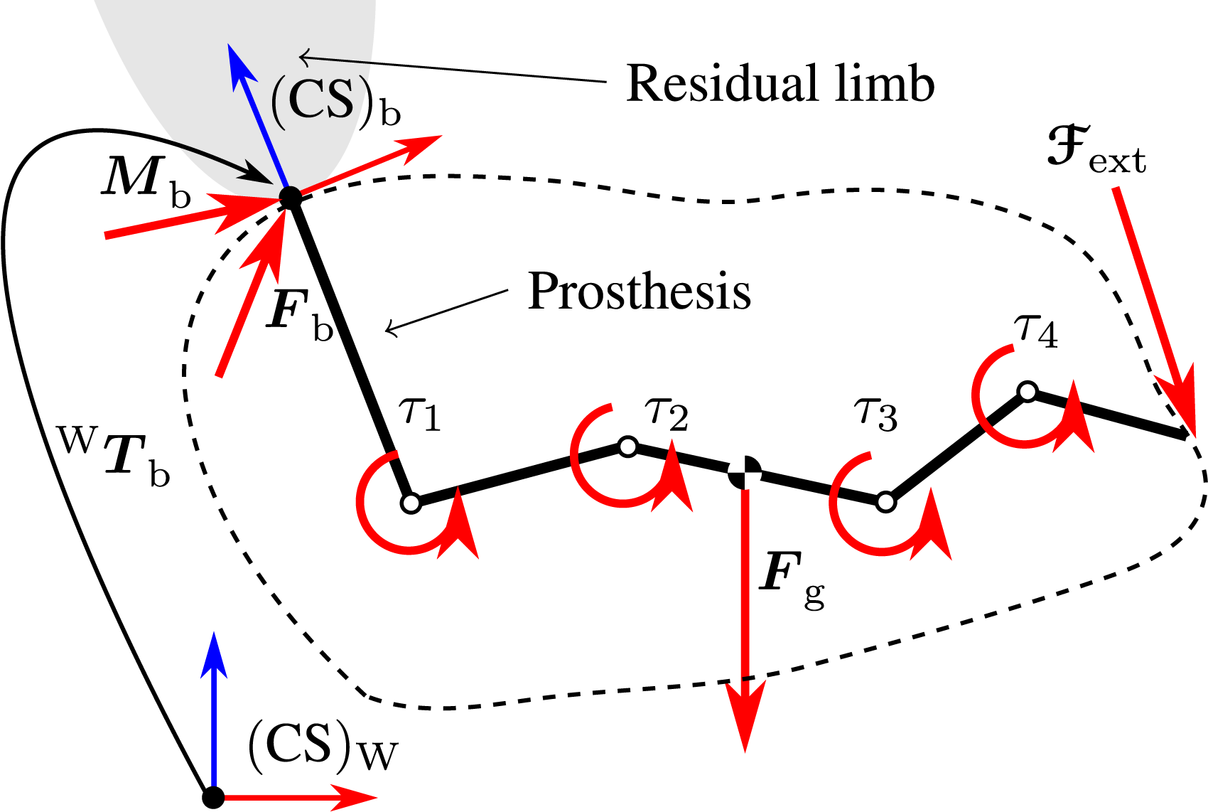
The matrix


More advanced concepts for force contact point estimations may be used from (Vorndamme and Haddadin, 2021). However, for this work, we rely on this basic version.
Finally, the sought reaction wrench is expressed in the base frame coordinates (in correspondence to a sensor) via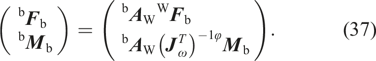
5.3.1. Practical remarks
Equation (36) allows to calculate a general wrench with respect to any contact point C at (CS)C, see Figure 7(b). However, the point C has to be chosen carefully in order to allow a general usage of
In order to obtain the most stable results for our prosthesis kinematics, we assume the wrench takes the form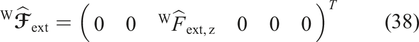


The aforementioned limitations can be overcome partly by running multiple variants of (39), (40) in parallel. For instance, forces in the direction (W
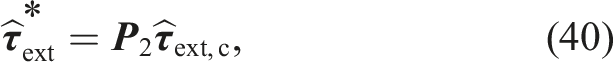
Finally, Figure 11 depicts the entire modeling and control scheme of the ANP.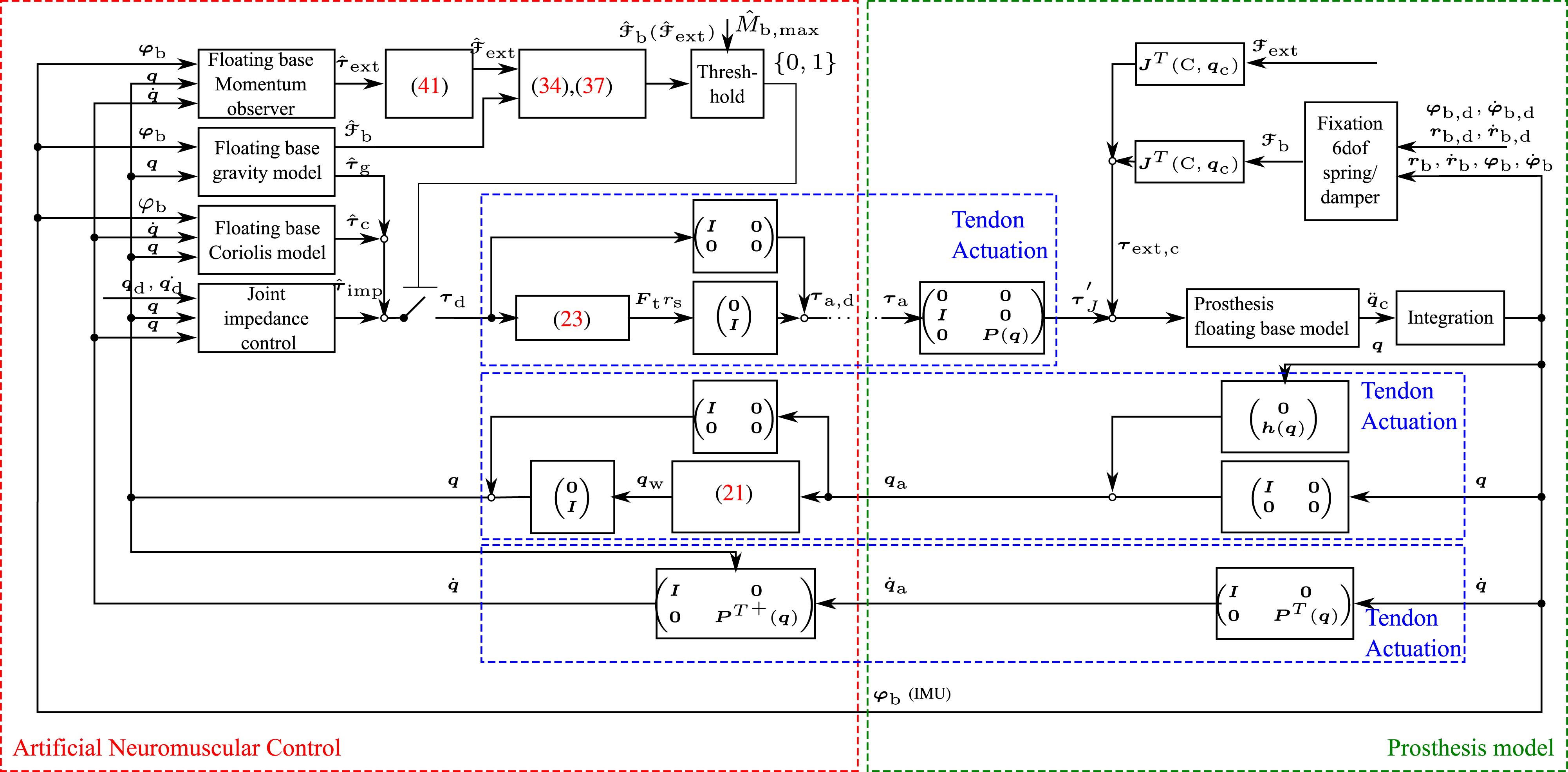
6. Experiments
In this section, the validity of the concept is experimentally tested on the ANP prototype. In addition to the experiments, the tests from Table 3 were successfully validated in simulation which may be found in the Appendix Section F. Also, the motion control (i.e., Human-like kinematics) and human-inspired contact response were successfully tested in experiment and may be found in the Appendix Section G. The following experiments focus on body awareness, contact awareness and the grasping validation of the ANP. The utilized model and plant parameters of the ANP may be found in the multimedia material. The experiments were performed by an unimpaired user, the first author of this work, in accordance with the declaration of Helsinki.
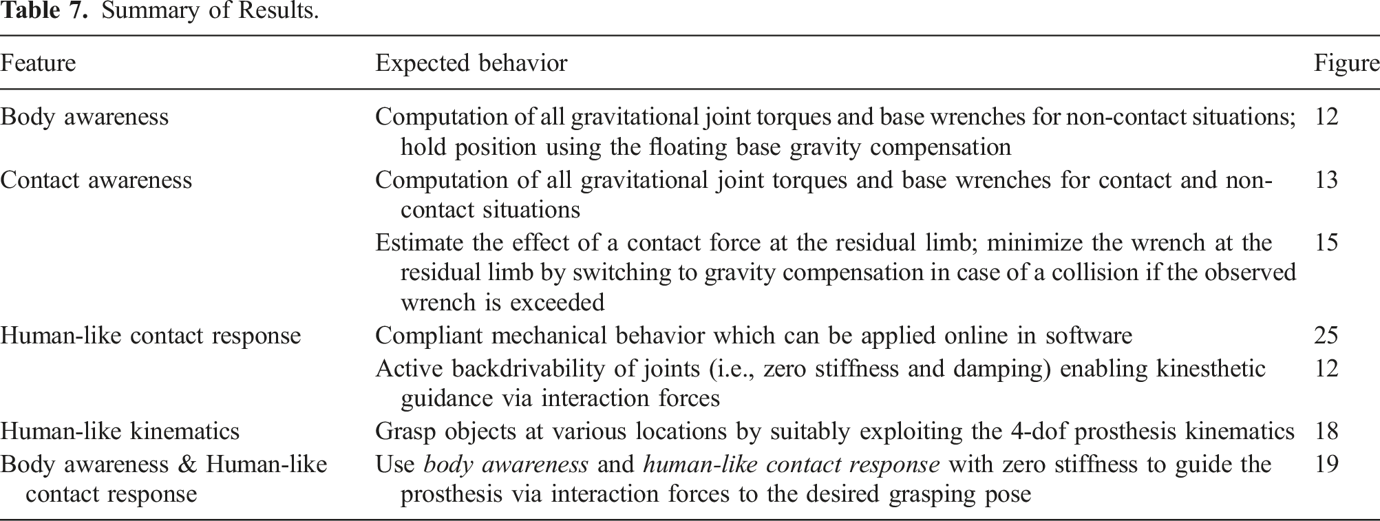
6.1. Body awareness
The body awareness is demonstrated by a human user interacting with the ANP, see Figure 12. In this context, also the active backdrivability of the torque controlled actuators is shown. During the experiment, only the floating base gravity compensation Experiment: Body awareness. The prosthesis is tilted by the human while the system is floating base gravity compensated. Consequently, the joints of the prosthesis do not move, unless an intended human contact occurs to move the joints to another position (gray areas), Δ = (113.2, − 38.6, 12.6) deg, {Eval.: F3, F6, F7, F8, F9, F11, T1, T2, T3, T4, T6, M9, M10, M12, M13, M15, M16}.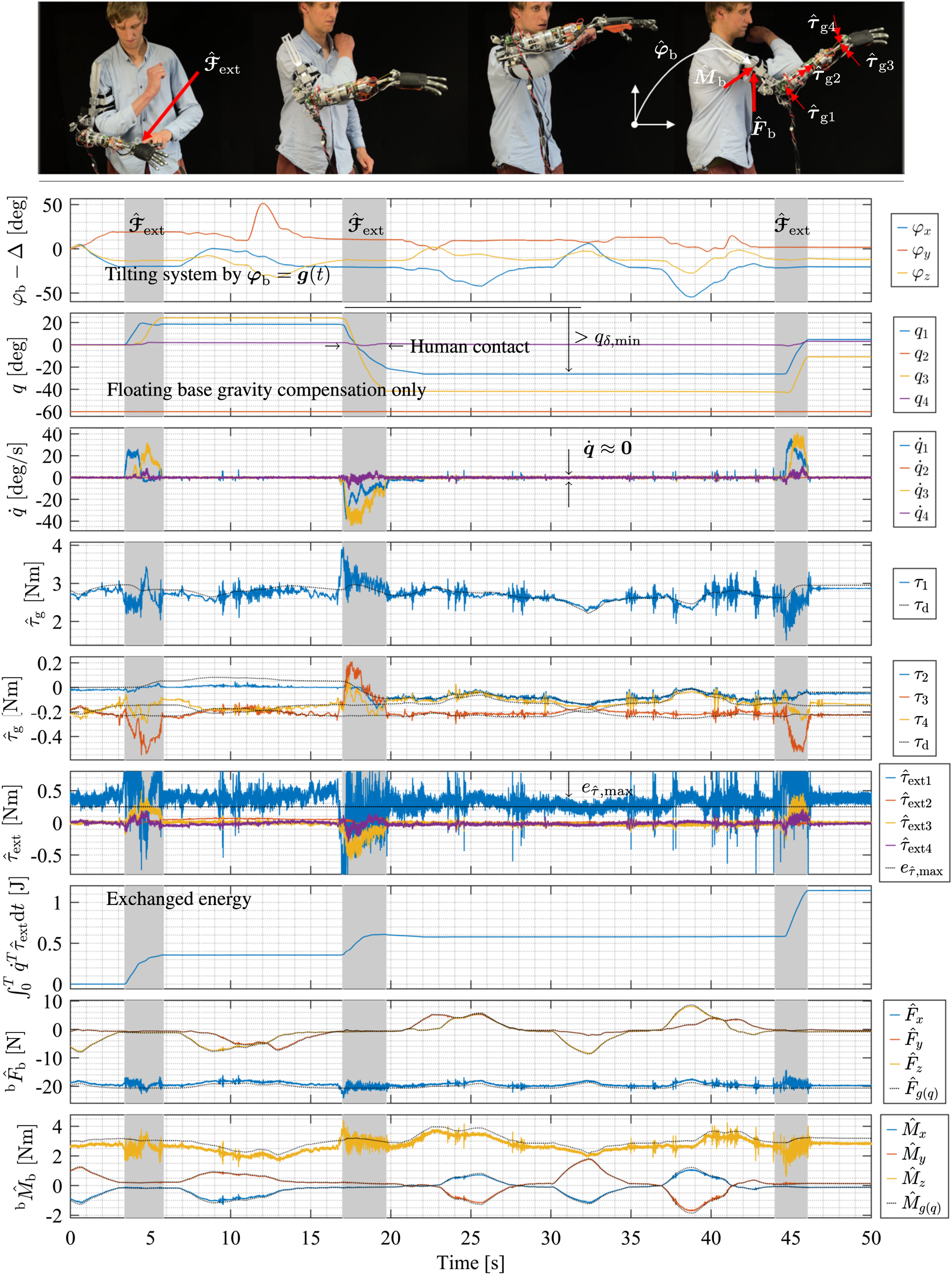
For comparison, an impedance controlled system with a stiffness of 10 Nm/rad would have stored an energy of Eimp = 2 × 0.5 × 10 × (20 × π/180)2 = 1.22 J.
The last two rows show the model-based base wrenches, which change in dependency of
Thus, the system from the figure is also equipped with a drift-free contact awareness, here applied in a contact-free case. As contact and body awareness are almost equal (black and colored lines), apart from the additional noise of the contact awareness, (F8) and (F9) can be confirmed by this experiment.
6.2. Contact awareness
The contact awareness of the ANP is used to estimate the contact force W Experiment: Contact awareness, {Eval.: F8, F10, F11, M17, M18}.
Finally, contact awareness is used to monitor the stress in the prosthesis base and to react with a protective control mode, see Figures 14 and 15. In the first experiment (see Figure 14), the prosthesis is programmed to move from q1 = 0 to q1 = −π/2. A collision arises from the contact between the prosthesis and the table. The methods for body and contact awareness are used to calculate Experiment: ANP runs into contact without collision detection, {Eval.: F4, F11, T5, T6}. Experiment: ANP collides with obstacle with collision detection/reaction, {Eval.: F9, F10, F11, F12, T5, T6, M17, M18}.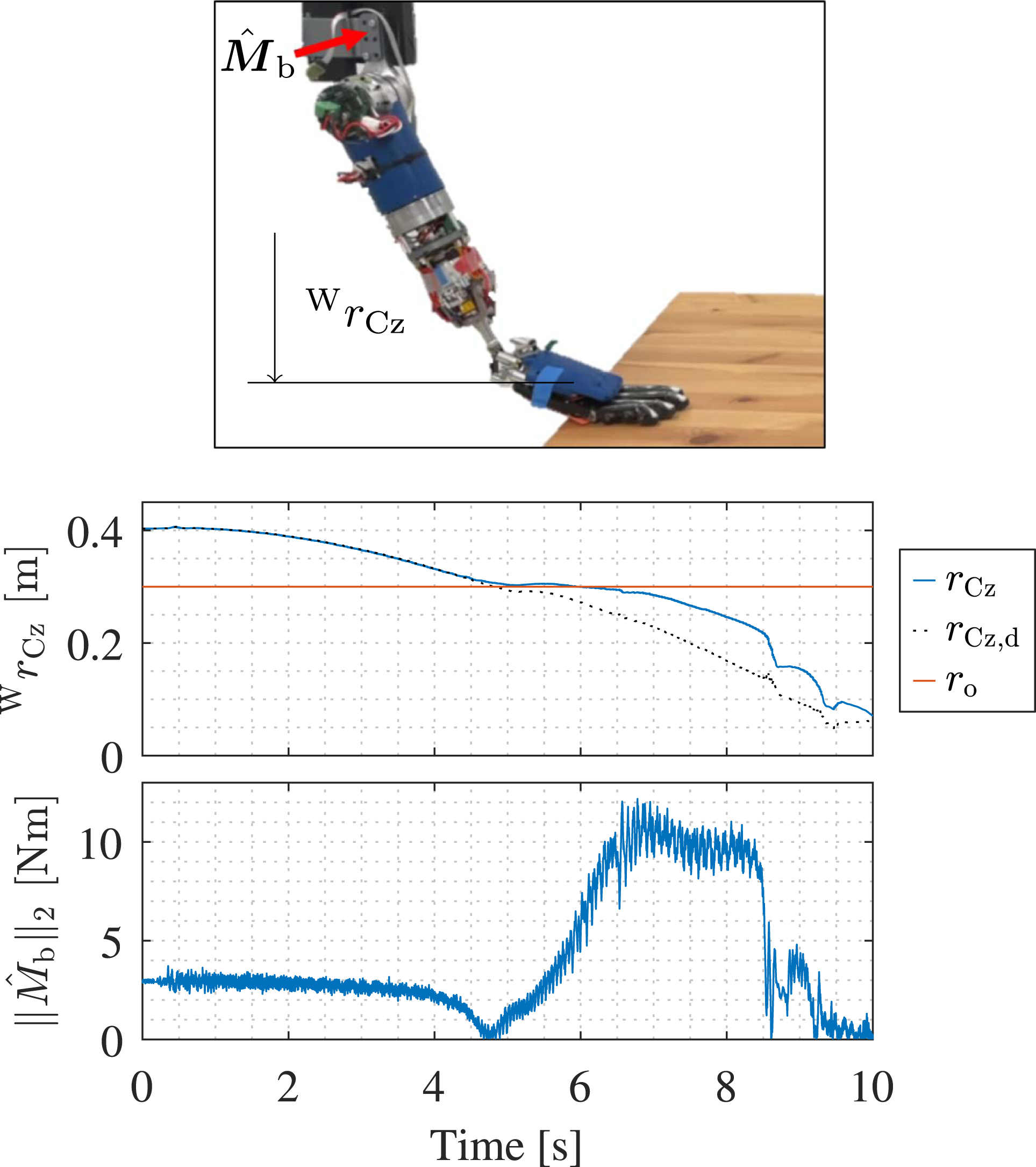
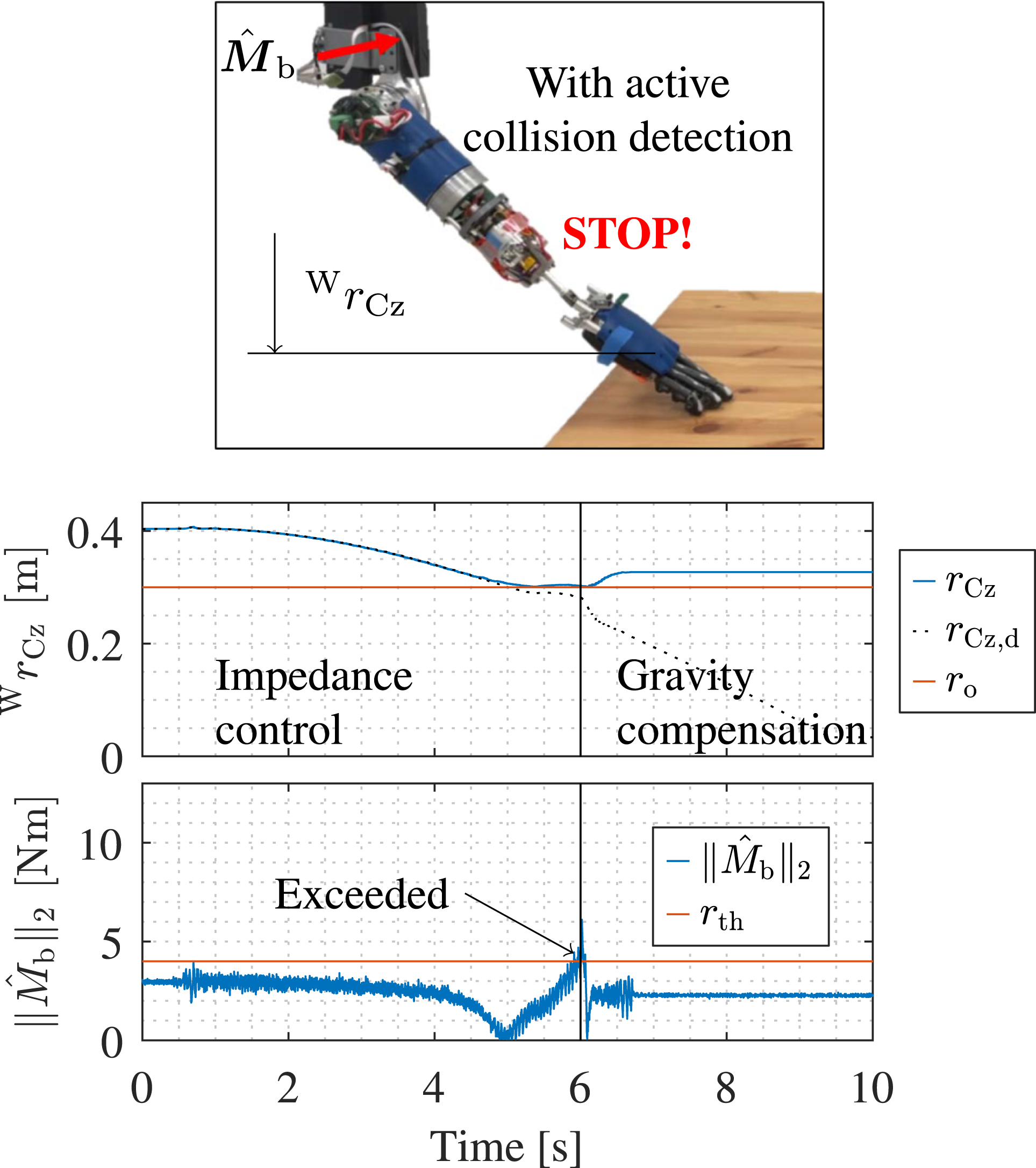
After the prosthesis collides with the surface, the base moment b
6.3. Grasping
In the following two experiments, the overall grasping capabilities of the developed robotic device are validated and we investigate how the novel 4-dof kinematics helps to fulfill complex daily grasping tasks.
The prosthesis is controlled by the user via a graphical user interface (GUI) on a smartphone, see Figure 16, which is further described in Section G.3 in the Appendix. The experimental setup, see Figure 17: Four different objects of daily use are placed on a table at the beginning of the experiment, specifically, a can of tomatoes (250 g), a can of tuna (125 g), a bottle of water (500 g) and a glass (300 g). The aim is to solely use the prosthesis to move all objects from the table top ① to the middle level of the shelf ②, and finally, to the top level of the shelf ③. The three different levels of heights and four different objects where chosen to encourage the operator to use different grasping poses with the prosthesis and thus to exploit the capabilities of the 4-dof kinematics. Thus, in total 24 different orientation changes are required to fulfill all experiments. Another object, a 1 kg bottle, which was grasped by the device, is depicted in Figure 17. Unimpaired user controlling the ANP via a GUI. Setup of the grasping experiment.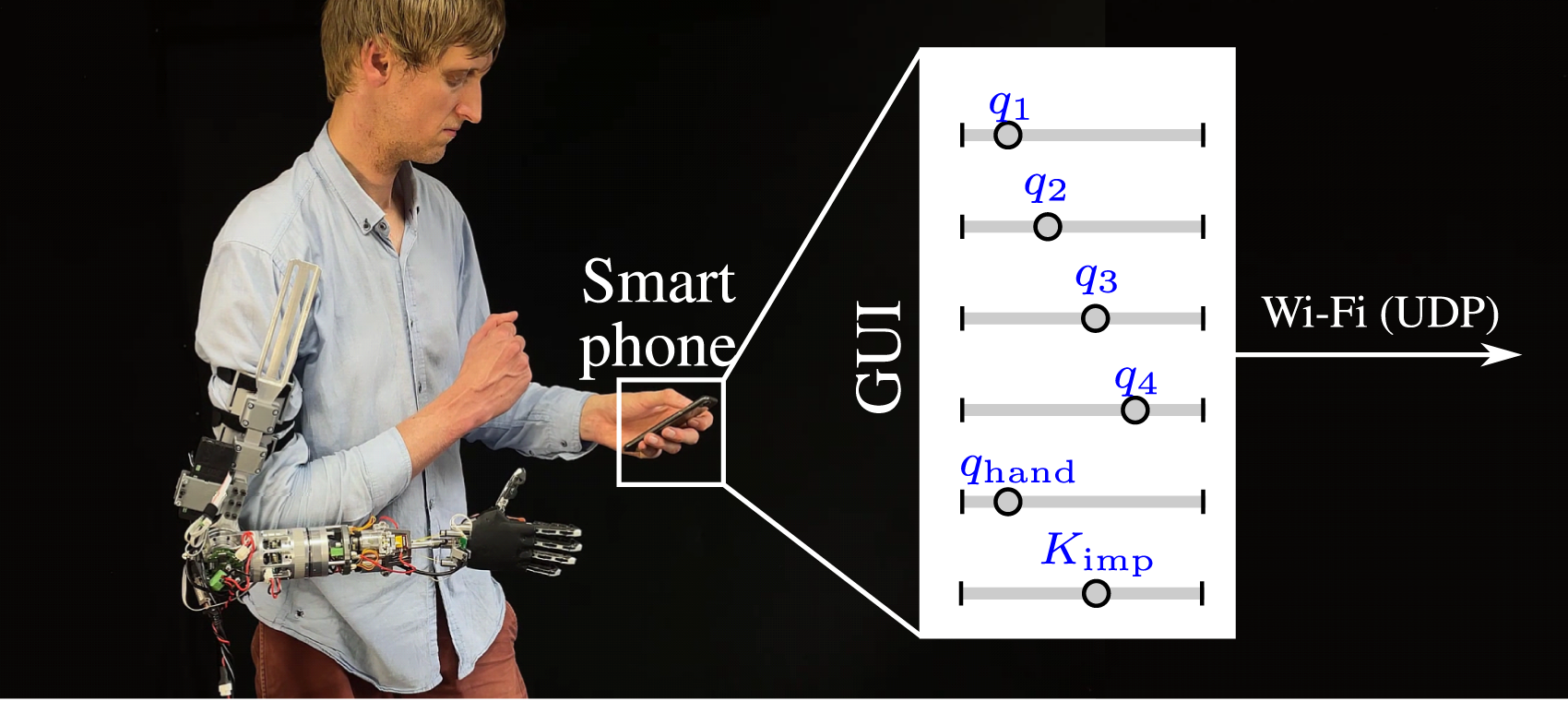
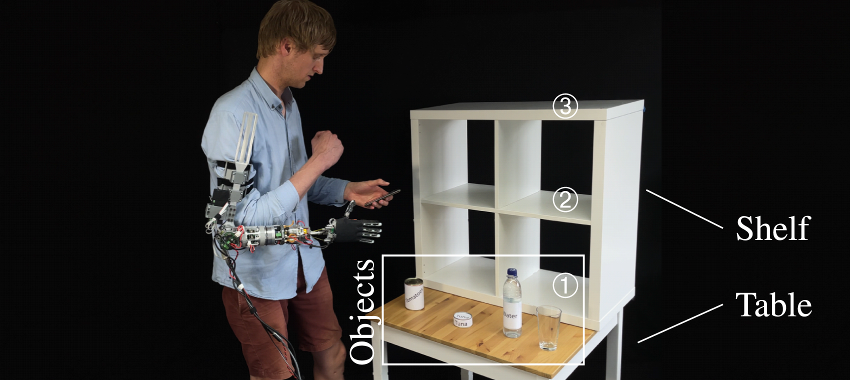
Figure 18 depicts 12 different grasping cases showing the grasping capabilities for different situations. The rows depict the experiments with varying objects (i.e., tomato can (1), tuna can (2), bottle of water (3), and glass (4)). The columns show the different locations (i.e. table top (a), the middle level (b), and the upper level (c) of the shelf). The figure is further analyzed in Section G.4 in the Appendix. Furthermore, the measured data for grasping the can of tuna is depicted and discussed in Section G.5 in the Appendix. Grasping validation for differ grasping poses using the Softhand Pro 2 (Della Santina et al., 2018), {Eval.:F13, T5, M19}.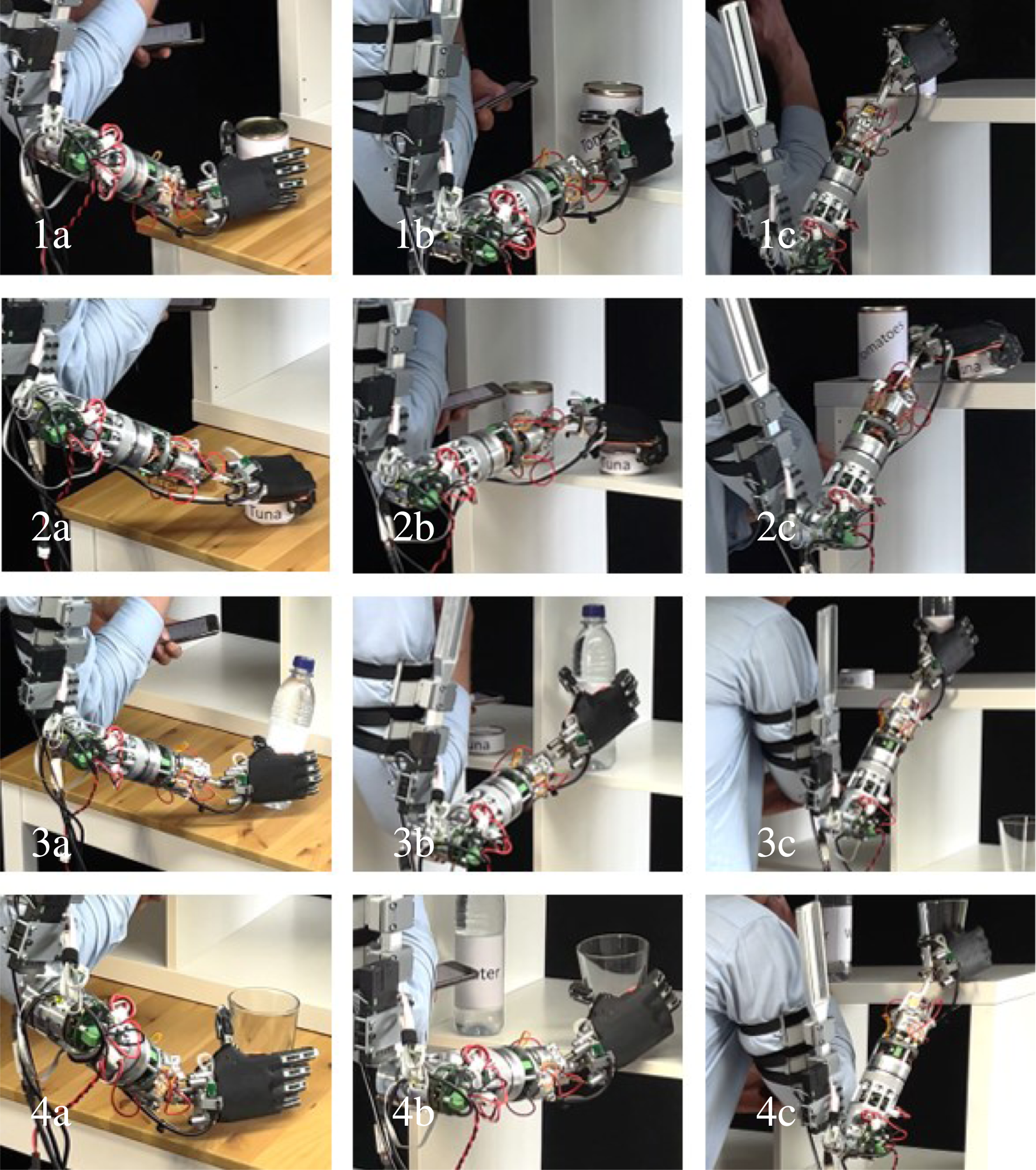
A final grasping experiment is performed in Figure 19 where the hand of the prosthesis is guided to the object via interaction forces in gravity compensation, instead of using the impedance controller and the smartphone GUI. The related data is depicted in Figure 31 in the Appendix. This experiment shows that the prosthesis can also be controlled by direct kinesthetic teaching. This experiment provides an example of how backdrivability and gravity compensation may be utilized in upper limb prosthetics, apart from achieving enhanced security of a low impedance prosthesis and simulating human limb behavior. Further information may be found in Section G.6 in the Appendix. Consequently, the grasping is evaluated in this final experiment (M19). Experiment: guiding the prosthesis via interaction forces to grasp an object, {Eval.: F6, F13, T2, T3, M19}.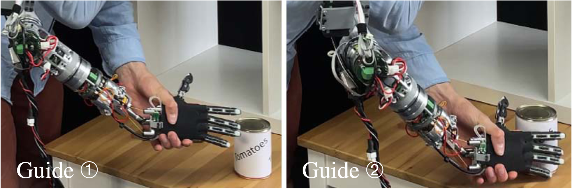
7. Discussion
In this section, the prosthesis capability, the design paradigm and the mechatronic device are discussed.
7.1. Prosthesis capability
In this work, novel human-inspired capabilities for upper-limb prostheses such as body awareness, contact awareness and human-like contact response were proposed, see Figure 1. It is hard to straight forward compare these capabilities with traditional prosthesis control methods such as velocity-based sEMG control (Lenzi et al., 2016), or human machine interfaces for prostheses (Resnik et al., 2014). Rather, our envisioned capabilities are better characterized as a novel system behavior or joint-torque-level autonomy, aiming to recreate key functionalities of the human neuromuscular system, such that the prosthesis can mechanically behave similar to a natural human arm if controlled appropriately. With this, the prosthesis shall autonomously react to and compensate for environmental influences, such as orientation changes or interaction forces, in particular without requiring additional user commands. Therefore, our approach is rather designed to coexist with or even complement widespread prosthesis control methods such as velocity-based sEMG control interfaces.
Our first prototype served the introduction of fundamental soft and tactile robotics modeling and control concepts to prosthetics. Following our novel design paradigm, body awareness, contact awareness and human-like contact response were realized by the simplest possible implementation. The contact awareness can, for example, handle both contact and non-contact situations well. However, due to the underlying observer system, the contact awareness produces more noise than the body awareness. Another trade off in the current design is that all prostheses joints require additional torque sensing. This significantly impacts the mechanical design approach, requiring space and weight, which otherwise could be used to optimize the prosthesis towards higher joint torques, speed or battery capacity. Still, traditional design approaches are known to not be able to render the human-like capability we target for. Also, the modeling and control approaches require more computation power in comparison to standard low-complexity control methods. However, given the current computational power, this is not a real limitation anymore, even for state-of-the-art mobile processors.
Clearly, there is still quite a gap between the current capability of the ANP and the antetype human body. Numerous improvements will follow in future works: (i) the extension of body and contact awareness and human-like contact response to the prosthesis hand, (ii) the ability to recognize multiple force directions and contact forces via proprioceptive measurements (Vorndamme and Haddadin, 2021), (iii) adding tactile skins (Mittendorfer and Cheng, 2011) integrated within the concept of body and contact awareness, (iv) develop a tactile feedback system for the prosthesis user using proprioceptive sensor information, (v) sophisticated human-inspired control laws for context-informed impedance adaptation and learning, (vi) the integration of aforementioned concepts into state-of-the-art prosthesis control methods such as velocity-based sEMG control, (vii) the upgrade of body and contact awareness on acceleration and velocity level.
7.2. User benefits
The benefits of the new prosthesis paradigm for future users are expected to be: 1. Increased mechanical safety: (i) impacts can be absorbed by the compliantly controlled elastic joints, and (ii) the risk for accidents or falls can be reduced as the device adapts to the environment due to its compliance. For example, a standard setting of the prosthesis could be a low joint stiffness of Kimp,i = {0… 5 Nm/rad}. Only, if the joints are actively controlled (e.g., 2. The human-like 4-dof kinematics allows to render human dexterity. Consequently, complex grasping tasks in restricted environments can be performed. The kinematics can be fully exploited once powerful HMIs are integrated. 3. Human-like motion and dynamics, based on joint impedance control, mimics the natural human limb in terms of inertia, stiffness, damping and contact response behavior. It systemically renders mechanical properties of human muscles and tendons closer than rigidly controlled prostheses, allowing more natural and fluid movements and control. Furthermore, less vibrations occur in comparison to position controlled devices (Ott, 2008; Vorndamme et al., 2016). 4. Low-level semi-autonomy: the prosthesis mimics natural capability of the human body such as gravity compensation or body and contact awareness. Consequently, the prosthesis is expected to behave closer to a human limb and therefore may better meet human expectations. 5. Proprioception: the prosthesis realizes a proprioceptive contact force measurement system using the joint torque sensors and model-based observers. These can be used as sensor for a haptic user feedback system in the future. 6. Guide and control via contact forces: the kinesthetic guidance via direct interaction forces allows to effortlessly adjust large orientation changes of the device. This feature may fulfill its full potential when joint positions/full configurations can be seamlessly stored and interpolated, or certain joints can be software locked. With this, even the functionality of some passive wrists (Cappello et al., 2023; Montagnani et al., 2013, 2017) can be reproduced by active control. 7. Socket protection: the contact awareness monitors and protects the residual limb attached to the prosthesis socket by suitable reflex control switching to gravity compensation or more sophisticated reflexes. 8. More functionality through high-level controllers: humans use stiffness and damping control for more efficient interaction with the environment and grasping. Modern human-inspired learning and adaptation algorithms have the potential to improve grasping and interaction performance.
In the following, the design approach and it implications is further discussed.
7.3. Design paradigm
The proposed sim2real-guided and human-inspired design paradigm provides two novel perspectives for prosthesis design. (i) The human-inspired design approach extends the degrees of freedom to realize more human-like behaviors in prosthetics. In this work, fundamental feedback and feed-forward algorithms have been developed. Future work may cover closer biological correspondences of human motor control, for example, by modeling the systemic functionality of human neural circuitry (Kuehn and Haddadin, 2017). (ii) The sim2real-guided design paradigm translates robotics modeling, design and control approaches to prostheses and builds on best practices in model-based design. The next section deals with the discussion on the prosthesis mechatronics.
7.4. Prosthesis mechatronics
In this work a mechatronic solution with close to human-like size and weight is introduced. As of today, many components necessary for such a device are not available on the market and advanced custom solutions had to be designed, showing the necessary design thinking in the mechatronics design.
Furthermore, state-of-the-art mobile processors are suitable for computing all necessary models, observers and controllers. At the moment, the prosthesis provides sufficient torque for lifting payloads up to 1 kg. A key objective for future versions should be to achieve human-level strength and speed. Currently, not all desired human motions can be executed in terms of wrist speed (see Table 8) and maximum torque. For the wrist design, a solution was found which allows joint-torque sensing combined with several degrees of freedom at close to human-level compactness. This is possible because the tendon stroke can be wrapped around the spool and the torque sensor is virtualized with the tendon force measurements. Yet, a set of stronger tendons (Toedtheide et al., 2021) seems necessary due to some failures at full loads after several operating hours. For performing systematic user testing, the current Technology Readiness Level (TRL) has to be systematically increased on the electronics level.
Overall, the presented first generation ANP has also principal limitations. For example, batteries and internal computation unit for the joint-level and coordination controllers are not integrated yet. Joint 1 and 2 and the electrical circuit boards are to be further minimized for providing additional design space. More specifically, let us assume a battery with a volume of 140 cm3 located in the prosthesis (e.g., a diameter of 63 mm and a height of 45 mm) and a second one of the same volume located at the prosthesis socket. This configuration could provide 3.3 h of pure load, 6.7 h of idle operation and 5.5 h considering a 20/80 profile of load/idle. The weight of the batteries would be 0.5 kg. 12 Alternatively, the battery could be fixed to the user belt. After some electronics iterations and standard mechanics robustification measures, the device is sufficiently mature for prosthesis applications outside the lab. Note that the fundamental technology is related to those established in state-of-the-art soft and tactile robotics (Haddadin et al., 2022) for which industry-standard and medical device regulation robustness was achieved on product level. The KUKA LBR Med, for example, shows that medical certifications and standards can be met with an advanced mechatronics concept (KUKA AG, 2023). Future hardware development will focus on further weight, size, robustness and joint torque optimization, clean cable guidance, housing, human machine interfacing and advanced task-level controllers.
7.5. Experiments
To date, the ANP has been tested under laboratory conditions in a mechatronic test-bench and by a single human expert user, the first author of this work, validating the specified capability such as body awareness, contact awareness, human-like kinematics, human-like contact response, and grasping. The focus of the experiments is on basic technological capability demonstration and validation for the ANP, and in general, exemplary for a device developed by the sim2real-guided design approach. In this context, the sole purpose of the expert user is to serve as a floating base and to produce typical human-induced control data for evaluating the device performance and demonstrating that execution of complex (grasping) tasks is possible. This includes typical trunk and upper limb motions as well as control inputs, which cannot be obtained on a pure technical test-bench. These tests are essential as complex physical reactions of close-to-real use cases can be investigated. In essence, the experimental results validate the proposed paradigm shift and show its readiness to be fused with state-of-the-art human-machine interfaces. Due to the given scope of research and the methods of evaluation (i.e., via the metrics M in Table 3), any potential bias on the part of the human expert user is expected to have a negligible effect on the scientific results. A bias generally occurs for studies on human behavior, which is not the case for this work. The floating base and tactile capabilities of the prosthesis, shown in Figures 12 and 19, are in fact mechatronic compensations which do not provide a favorable mode of operation or interaction, which a biased user could take advantage of. For Figure 18, the grasping experiment, device was capable of performing versatile grasping tasks according to M19 in Table 3. This metrics is true regardless of the pilot and its potential bias. Consequently, a user bias is expected to be insignificant for this research. In future work, the next system generation with higher TRL will be validated with impaired users.
Note that due to the focus in current experiments on principal capability validation and verification, no statement about user acceptance, ergonomics or true quality of human-device interaction of amputees is yet possible. As a single user experiment suffices these goals, statistically relevant data was not necessary to be generated and is thus also not meaningful at the current stage.
For testing and validating the new paradigm with amputees, several steps are still necessary: (i) The robustness, safety, and overall TRL of the next generation device need to be increased by the measures described in the mechatronics design paragraph. (ii) The socket of the impaired pilot, a battery and a computation unit need to be integrated into the prosthesis. (iii) An sEMG-based control-interface needs to be integrated. (iv) The proposed key capabilities from Figure 1 need to be integrated into an HMI concept. Currently, for example, the joint stiffness adaptation is adjusted via a smartphone GUI. This needs to be connected to user inputs as described in the user benefits paragraph. Furthermore, other capabilities such as storing key points and interpolating motions, learning of entire manipulation skills, and the active control of passive wrist behaviors (Cappello et al., 2023) can further increase the versatility and benefits for prosthesis users. (v) Suitable experiments and metrics need to be defined to fully evaluate the proposed capabilities from Figure 1 (vi) Also, for performing human trials with impaired users and subsequent clinical evaluation, the next generation device needs to go through full ethics approval with underlying risk analysis and mitigation, safety-rated development, and development according to certified quality processes.
Once aforementioned steps are fulfilled, the next generation device will be tested in statistically relevant user trials with impaired users.
7.6. Most notable results
8. Conclusion
In this paper, we introduced a novel prosthesis class aiming to render key capabilities of the human neuromuscular system and hereby contributed via (i) novel prosthesis capabilities, (ii) a new robotic prosthesis device, and (iii) a novel prosthesis design paradigm. We introduced the Artificial Neuromuscular Prosthesis ANP, which imitates behavioral aspects of the human body in terms of its (i) body awareness, (ii) contact awareness, (iii) human-like contact response, and (iv) human-like kinematics as defined in the framework of this paper. Consequently, the ANP behaves mechanically similar to a human arm—in the sense of our target anthropomorphic design specifications. To achieve this goal, we introduced a novel development paradigm for upper-limb prostheses, which is characterized by (i) a biologically inspired mechatronic solution, and (ii) the subsequent rigorous specification, mathematical modeling, control, simulation, design and evaluation of the prosthetic device. We presented the novel custom-developed ANP mechatronics, which consists of a four degrees-of-freedom elbow-to-wrist kinematics, joint-torque controlled actuators, a tendon-driven wrist, an IMU for spatial orientation sensing—at size and weight of 1.7 kg without hand and battery. We introduced soft and tactile prosthesis control methods for the ANP, consisting of a floating base gravity compensation, joint-level impedance control with damping design, and momentum observation for contact wrench monitoring - all of them being new to the prosthesis world - to render the desired functionalities of the human archetype.
With this work, we demonstrated that the latest concepts from robot mechatronics known from soft and tactile and humanoid robotics can indeed be translated to upper-limb prostheses and promising solutions in terms of weight, size and overall capability are found. In this regard, future steps for battery integration were discussed. We also detailed how such a complex and advanced design can be realized in just a single prototype generation with our simulation-guided design approach. Overall, a significant technological leap towards more human-like robotic prostheses could be achieved.
In dynamic simulations and real-world experiments, we could validate all desired prosthesis functionalities such as (i) body awareness, (ii) contact awareness, (iii) human-like contact response, (iv) human-like kinematics and (v) grasping as mathematically defined in this work. The simulations turned out to be highly eligible for the model-based design and in very good agreement with the experimental system behavior.
While the system mechatronics and its controllers were rigorously validated, future work focuses on developing the next generation to improve the TRL, robustness, weight, size, torque density, speed, clean cable guidance, housing, human machine interfacing and more advanced task-level HMIs and controllers.
With this, user-centered and even clinical studies will be performed, aiming to cover a statistically relevant number of participants. These studies should focus on (i) user acceptance, (ii) device ergonomics and (iii) the human-device-interaction using state-of-the-art prosthesis human machine interfaces.
Supplemental Material
Supplemental Material
Supplemental Material
Supplemental Material
Footnotes
Author’s note
All of the authors reviewed this paper.
Declaration of conflicting interests
The author(s) declared no potential conflicts of interest with respect to the research, authorship, and/or publication of this article.
Funding
The author(s) disclosed receipt of the following financial support for the research, authorship, and/or publication of this article: This work was supported by the European Union’s Horizon 2020 research and innovation programme as part of the project SoftPro under grant no. 688857. We gratefully acknowledge the funding of this work by the Alfried Krupp von Bohlen and Halbach Foundation. This work was supported by the Federal Ministry of Education and Research of the Federal Republic of Germany (BMBF) by funding the project AI.D under the Project Number 16ME0539K.
Supplemental Material
Supplemental material for this article is available online.
Notes
Appendix
References
Supplementary Material
Please find the following supplemental material available below.
For Open Access articles published under a Creative Commons License, all supplemental material carries the same license as the article it is associated with.
For non-Open Access articles published, all supplemental material carries a non-exclusive license, and permission requests for re-use of supplemental material or any part of supplemental material shall be sent directly to the copyright owner as specified in the copyright notice associated with the article.